
International Journal of Scientific & Engineering Research, Volume 6, Issue 1, January-2015 403
ISSN 2229-5518
Magnetorheological Landing Gear for UAVs
– A conceptual design
M. Hari Prasad, K V Gangadharan
Abstract—Thedevelopment of Unmanned Air Vehicles (UAVs) for both military and civilian applicationslead the opportunites for the development of advanced technologies to improve their operational performance. Due to various mission requirements UAVs will carry different types of payloads which change the total all-up weight. The landing gears of the UAVs should be optimized to the changing weights and various sink speeds. Conventional landing gears are optimized for particular set of parameters and not efficient in all conditions. A novel solution to this problem is to implement a smart damping using magnetorheological (MR) fluids. This paper presents a design mtheodology that enable MR landing gear to be optimized, both interms of its damping and magnetic circuit performance using Magnetorheological Grease(MRG). The design approach focuses on the impact of landing phase of an UAV where large variations in the UAV mass, landing speed, sink speed makes MR shock absorber a potential solution. The usage of MRG in the present design overcomes the problem of sedimentation that exists in regular MR fluidswith long term usage.
Index Terms—Unmanned Air Vehicles (UAV),Aircraft landing gear, Electrorheological , Magnetorheological, semi-active damping, shock absorber, smart fluids, shock absorber, shimmy damper, adaptive impact absorption
————————————————————
he design of Aircraft Landing Gear, which is considered “the essential intermediary between the aeroplane and catastrophe”, is one of the more fundamental aspects of air- craft design. Various designs and configurations are evolved during the course of development. The task of a landing gear designer is to define a reliable gear that meets all of the land- ing and take-off requirements. The aircraft landing gear con- sists of shock absorbers, retraction mechanism, steering, shimmy control, tires, wheels and brakes. This represents 3.5 to 7% of the gross weight and 2 to 4% of basic aircraft cost. To utilize the landing gear for its best performance, it is planned to modify the electrically tunable shock absorber and electri- cally operated brake system. The first part is to develop shock
absorber and the second one is to develop a brake system.
Aircraft shock absorbers are designed as passive devices with characteristics satisfying the hardest expected landing impact conditions. However, in the majority of cases, the variation of real working conditions is below these critical levels and the passive shock absorber is too stiff to optimally perform the landing scenario. In contrast to passive systems this research is to develop an active adaptation of energy absorbing struc- tural elements, where the system of sensors recognize the type of impact loading and activate energy absorbing components realizing a pre-design strategy of optimal impact energy dissi- pation. Present landing gear shock absorbers works on the principle of hydraulic fluid flow control using a metering pin to change the orifice dimension during landing operation. The design of landing gear is optimized for particular operational characteristics.
————————————————
• Professor, Dept of Mechanical Engg., NITK, Surathkal, Karnataka, India
E-mail: kvganga@gmail.com
There is no control on the damping characteristics for different missions and operations which make the landing gear not to perform to its optimum characteristics.One of thesolutions for the above problem is to introduce an active control shock ab- sorber to meet the various mission requirements. The active controllability can be achieved using controllable fluids such as Magenetorheological fluids (MRF), Electrorheological fluids (ERF) and Magnetorheological grease (MRG) etc. In order to influence the damping force at faster rate along with necessary control, Magnetorhrological dampers are candidate solution to achieve similar capabilities as stated preiviously.
Aircraft brakes absorb kinetic energy when brakes are ap- plied. To take care of the energy absorption, sufficient force is to be generated by the brake pads on the discs. Presently these pads are actuated by caliper type brakes with hydraulic fluids and the required force is generated by the fluid pres- sure. In UAVs these brakes are actuated by an electromechan- ical actuator, to increase the fluid pressure. In order to elimi- nate these actuator and hydraulic braking system, it is planned to develop piezo based actuator which is able to deliver the required force and displacement of the brake pads.
The Unmanned Air Vehicles (UAV) are developed from few grams to few tonnes weight for different application and per- formance requirements. Smaller UAVs will be fitted with fixed landing gears made of metal or composite materials to take the landing loads. Medium weight class UAVs will have different types of landing gears from rubber shock absorbers to oleo-pneumatic type with retractable mechanisms. Most of the landing gears are adapted or fitted from the small manned aircrafts, due to their proven characteristics and clearance from the certification agencies.
Present research is focused to develop a smart landing gear to meet the requirements of medium class UAV. The paper is focused on the design methodology for the development of
IJSER © 2015 http://www.ijser.org
International Journal of Scientific & Engineering Research, Volume 6, Issue 1, January-2015 404
ISSN 2229-5518
MRG based landing gear to meet the optimum requirements. The research is focused to control the damping characteristics through electrically controlled magnetic flux which inturn controls the flow characteristics of MRG. In addition to this the system also contains a pneumatic spring to support the UAV during parking and in the absence of electrical power.
MR landing gears comprise more or less same modules in comparision to conventional oleo-pneumatic landing gear. The modifications being in the design of shock absorber strut. In MR landing gears the fluid used is basically a contorllable flu- id. The control characteristics are altered by changing electro- magnetic flux through the control of current as per the re- quirements. Studies revealed that 11.8% load reduction was achieved as a result of use of MRF in shock absorber[1]. Many research articles are appearing with different titles such as semi active control of landing gear, improved impact absorp- tion of landing gear, active control of landing gear etc. Some of the research reported in open literature are discussed in subsequent paragraphs.
Magnetorheological landing gear design and validation has been carriedout bymany institutes and organizations. One among them is ADLAND [2]. The design methodology for MR landing gear shock strut has has been illustred in [3]. The design methodology aimed at packaging, optimizing magnetic design and to produce desirable behavior for wide range of impact conditions unlike passive device. A 2DOF simulation studies were performed to simulate the exact drop test condi- tions. A widely adjustabale valve control ratio resulted in
of reducing loads by using active control gear. Such gear is effective in reducing the loads transmitted to the airframe. A non flying prototype of semi-active landing gear built by MR fluid shosck absorber for ageneral aviation aircraft was tested for performance [8]. The results revealed that with proper control the ground loads can be significantly reduced. Similar drop test studies were also carried by Zhu et.al [9]. The studies served to understand the MRF damper for aircraft landing gear application. Acomparaision of various MR fluids and their characteristics are describled for application of landing gears [10].
Many studies were conducted by in academic institutes and industries for the development of MRF based landing gear. Still it is not evident that any real usage of the MRF landing gear in commercial application. This is due to stringent relia- bility and certification issues. However the research continues to develop a smart and reliable system which meets the indus- try requirements. This will help realize the product in com- mercial market.
Magnetorheological grease (MRG) has been developed to overcome the settling of ferro particles in both ER/MR fluids. Due to settling, the performance of devices will degrade over aa period and not suitable for the devices used for long term application, such as aircraft landing gears. The synthesis and magneto mechanical properties of MR grease are brought out in [11]. The MR characteristics of MRG are similar to MRF. Some of the basic properties of MRG are tabulated in table 1.
TABLE 1
Typical Values of MRS fluid
damping levels to accommodate large range impact condi- tions. The study helped is demonstrating the feasibility of an MR landing gear. The manufacture and testing was in the studies made by the same group [4]. It is emphasized that to validate the design, a quasi-steady MR valve function must beformulated analytically, without the need to update the yield stress and viscosity parameters. The study is performed at low velocities. There is a need to carryout the same with
Max. Yield Strength,τ y
Maximum field Plastic viscosity, η Operable Temp range Response time Density
50-80kPa
Tested up to 1.2 T
5-90Pa s
-65o -170oC
< milliseconds
3-4 g/cm3
high velocities.
Landing gears are also designed for improved impact absorp- tion [5]. Two technologies (piezoelectric and magnetorheolog- ical fluid)for adaptive landing gear have been stuied in which the piezoelectric valve can control the shock force and adapt the stiffness of shock absorber depending on several landing conditions. Scaling is required for developing a bigger shock absorber for large aircrafts.
Several numerical simulation studies for predicting the per- formance and control issues are studied [6]. Many prototypes are developed and validated for performance test byusing drop tests [7]. Dynamic loads and vibrations resulting from runway and taxiway unevenness are serious concerns for fa- tigue life. The experimental investigation reveals the feasibility
The modes of operation of MR fluid devices are flow mode
(fixed plate mode, valve mode), shear mode (clutch mode),
squeeze mode (compression mode)and any combination of
these three are stated in [12]. Diagrams of the three basic
modes of operation are shown in Figure 1.
Fig. 1. Basic modes of operation of MR fluid devices
In flow mode, MR fluid is made to flow between static plates
by a pressure drop and the flow resistance can be controlled
IJSER © 2015 http://www.ijser.org
International Journal of Scientific & Engineering Research, Volume 6, Issue 1, January-2015 405
ISSN 2229-5518
by the magnetic field which runs normal to the flow direction. The flow mode is used in devices such as servo valves, damp- ers, shock absorbers and actuators. In the shear mode MR flu- id is located between surfaces moving (sliding or rotating) in relation to each other with the magnetic field flowing orthog- onally to the direction of motion of these shear surfaces. The characteristic of shear stress versus shear rate can be con- trolled by the magnetic field. Clutches, brakes, chucking and locking devices, dampers and structural composites work on the shear mode principle. In squeeze mode, the distance be- tween the parallel pole plates changes, which causes a squeeze flow. In this mode relatively high forces can be achieved and this mode is suitable for damping of vibrations with low am- plitudes and high dynamic forces.
The present study is considered using the flow mode for the development of shock absorber for the landing gear.
The data does not represent any typical existing UAV. The data considers typical parameters of some of the UAVs in a particular class.
The assumed data for the current studies are total mass of the
UAV is 2000 Kg, Maximum Speed of aircraft on ground is 120
Km/hr and maximum vertical sink speed is 3.048 m/s and
load factor 2-3. The landing gear geometrical arrangement is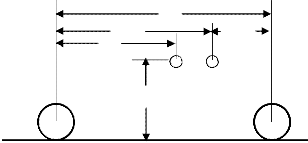
shown in Figure 2.
F
N M
L
J
NG MG
On the basis of previous assumptions, the necessary data for shock absorber sizing has been generated. The details of the same have given below. All the formule are considered from the regular landing gear design principles [13][14].
Shock absorber travel (Ss ) = ![]() (1) Neglecting tyre travel (nt St ) and substituting the previous da-
(1) Neglecting tyre travel (nt St ) and substituting the previous da-
ta the shock absorber travel should be 0.2m.
The diameter of the shock absorber is given using the formula, Ds = 0.041 +0.0025 (Pm )0.5 (2)
Where Pm is load on main landing gear in lbs and Ds will be inches. Considering the main landing gear load is about
1000x2.2 lbs, the diameter of the shock absorber is roundedoff to 0.050 m.
The landing gear will have three different positions basing on the operation. The positions are (i) Static (ii) Extended (iii) Compressed. As per the industry standards the ratio of the positions for small aircrafts are assumed,
Static to extended - 2.1/1
Compressed to static - 1.9/1
Considering the above and maximum load on main landing gear 10000 N,
Static load - 10000 N Load on fully extended condition - 4761.9 N Load on fully compressed condition - 19000 N
On the basis of the above data, the pressure & volume re- quirements are,
Cylinder bore diameter - 0.050m
Area of Piston - 0.00196 m2
Static pressure (P2 )= Static load/Area of piston
= 10000/0.00196 = 5001.3915 kPa
NG: Nose Landing Gear MG: Main Landing Gear
Fig. 2. Geometrical arrangement of Landing gear
F = 3.400 m, N = 3.088 m, M = 0.312 m, L = 2.863 m
J = 1.165 m
The loads on the gear struts are computed are as follws:
During fully compressed position, the piston in the pneumatic chamber will be moved to maximum position thereby fully compressing the air/nitrogen. The air volume at full com- pressed position is assumed to be 10% of fully extended posi- tion. Hence the volume in fully compressed position is,
V3 = 0.1(Stroke x Piston Area)
= 0.1(0.2x0.00196)=0.392x10⁻⁴ m3
Using 1.9/1 compression ratio,
Max. Pressrue in strut (P3 ) = 1.9x p2 = 9502. 64385 kPa
During fully extended condition the volume of air (V1 ) is,
IJSER © 2015 http://www.ijser.org
International Journal of Scientific & Engineering Research, Volume 6, Issue 1, January-2015 406
ISSN 2229-5518
V1 | = | V3 + Displacement |
= | 0.392x10⁻⁴ + (0.2x0.00196) | |
= | 4.312x10⁻⁴ m3 |
To estimate the pressure at fully extended condition (p1) we
use the basic gas equations, i.e
P1 V1 = P3 V3
P1 = P3 V3 /V1
= 9502. 64385x0.392x10-4/4.312x10-4
= 862.9852kPa
Similarly the Static volume(V2 ) is P1 V1 /P2 =0.742x10⁻⁴ m3
The summary of the above data is presented in Table 2.
TABLE 2
Summary of shock absorber data
Fig. 3. Arrangement of Landing gear
On the above estimated data, the shock absorber initial design was made. Majority of the shock absorbers designed using MR fluids in flow mode condition are with a moving piston along with electromagnetic coil in it. The MR fluid will flow through the annulus between piston and body of the cylinder. The disadvantage in these designs are, the electrical connec- tion will also be moving along with the piston and the electri- cal connection will be difficult as the wires will be passing through a lengthy piston rod. Any sort of maintenance will not be that easy. To overcome such difficulties, a unique de- sign was evolved. The arrangement is for ease of maintenance and electrically safe. The schematic arrangement of the major components are shown in Figure 3.
The basic elements are, pneumatic chamber in the top, fluid flow control module in the middle, MR fluid chamber at the bottom. The top and bottom chambers are integrated to the flow control module. The flow control module will hold all the electromagnetic coil and elements for the magnetic flux path. The top and bottom chambers are fabricated with non magnetic materials, so that the flux leakage will be minimized. The flow control module is manufactured with magnetic ma- terials expcept the coil housing, coil cover and flow directing plates. All the items are properly machined with very close tolerances to maintain the geometric and positional require- ments. The tyre is of standard aircraft quality to with stand the static and dynamic requirements.
The details of the various components are described subse- quently.
During touch down or landing condition, due to vertical de- scent and weight of the aircraft, the pistion rod will move in- side pushing the MRG though the flow control module. The flow control module will regulate the flow of the MRG to the top chamber. As the flow of the fluid increases its volume in the top chamber, the piston in the top chamber will start com- pressing the gas inside the chamber and increases its pressure. The change in pressure also acts as a vertical force on the bot- tom piston. Once the gas is fully compressed, the movement of the pistons will be stopped. The pressure inside the top chamber is so high, that it is sufficient to float the UAV on the pneumatic pressure. As the gas is fully compressed, it will slowly expand and moves piston downward to a static posi- tion. Once fully compression is achieved, the magnetic flux will be switched off, so that the MRG will flow downward easily while the gas is in expansion condition. Thus the land- ing gear will settle in the static position. Once the takeoff is completed, air pressure pushes the pistion to the bottom posi- ton, thus the piston in bottom chamber will also be pushed down to the fully extended condition. The power-on condi- tion will be only during landing condition. The velocity of the compression stroke will be regulated to achieve the desired damping properties.
The solid model of shock absorber isshown in Figure 4. The model shows the internal arrangement of the pistions. How- ever the flow control module is not clear about the arrange-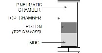
IJSER © 2015 http://www.ijser.org
International Journal of Scientific & Engineering Research, Volume 6, Issue 1, January-2015 407
ISSN 2229-5518
ment of components. The details of flow control module have been described in subsequent Figure 5.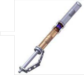
Fig. 4. Engineering model of landing gear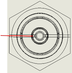
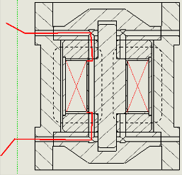
Fig. 5.Magnetic coil arrangement in flow control module The flow control module comprises a magnetic coil wound on analuminium bobbin. The two ends of the coil wires are taken up through a cut in the shaft and through a flow diverting plate and through the body. The same is indicated through
the red colour lines. The flux path is shown in dotted lines. The fluid flow will be between body and plates for magnetic flux return path. A cylindrical cover made up of aluminium cylinder is provided, so that the fluid will not come in contact with the coil at any time.
By fixing the other assembly on both sides of the flow control module the total assembly will be free from any leakages.All parts are fabricated with suitable materials. The machined components before assembly are shown in Figure 6.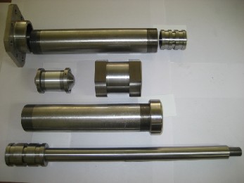
Fig. 6. Machined parts for landing gear assembly
The study gave an insight in to the design process for develop- ing a smart landing gear using MRG controllable fluid. The design being novel and unique will give more benefits for practical implementation. However simulation and experi- mental results need to be carriedouton the above design for various loads and configurations. Further studies have to be conducted to conclude the results. This will help the research- ers to design, develop and evaluate the “Adaptive Landing Gear “ or “Smart Landing Gear for UAVs”.
The authors are indebted to Shri P Srikumar, Outstanding Sci- entist and Director, ADE for his continued guidance, support and according permission for publishing paper. We record our grateful thanks to Dr ACR Pillai (Rtd), Group Director, ADE and KG Rammanohar, Group Director for their unstinted support and guidance.
[1] ZhingniewSkorupka, “Magnetorelogical fluids as method for active controlling of landing gear shock absorber characteristic”, Transaction of the Institute of Aviation No.207,Warszwa.
IJSER © 2015 http://www.ijser.org
International Journal of Scientific & Engineering Research, Volume 6, Issue 1, January-2015 408
ISSN 2229-5518
[2] Adaptive Landing Gears for Improved Impact absorptioin (ADLAND), Project No.IST-FP6-2002-Aero 1-502793-STREP, EU Re- search project.
[3] D C Batteerbee, N D Sims, R Stanway and ZbigniewWolejsza, “Mag-
netorheological Landing Gear, Part 1: Design Methodology”, Dept of
Mech. Engg,, The University of Sheffield, Sheffield, S1 3JD, UK
[4] D C Batteerbee, N D Sims, R Stanway and ZbigniewWolejsza, “Mag- netorheological Landing Gear, Part 2: Validation using Experimental Data”, Dept of Mech.Engg,, The University of Sheffield, Sheffield, S1 3JD, UK
[5] G. Mikulowski, “Advaned Landing Gears for Improved Impact Ab-
sorption”, 11thInternational Conference on New Actuators, Bremen, Germany, 8-11 June 2008.
[6] Gian Luca Ghiringhelli, StefaniaGualdi, “Evaluation of Landing gear
semi-active control system for complete aircraft landing”.
[7] William E Howell, et. al, “F-106B Airplane Active Control landing
Gear Drop Test Performance”, NASA Technical Memorandum
102741, 1990.
[8] Gian Luca Ghiringhelli, “testing of a semi-active landing gear control for a general aviation aircraft”, Poloitechnico di Miland, Italy.
[9] Zhu et.al, “Experimental Research on Aircraft Landing Gear Drop
Test Based on MRF Damper”, Procedia Engineering 15(2011)4712-4717 [10] M. Hari Prasad, K V Gangadharan, “Research Trends in Controllable
Fluids for Landig Gear Applications”, International Journal of Scientific
& Engineering Research,Volume 5, Issue 7, July-2014
[11] M. Hari Prasad, K V Gangadharan,”Synthesis and Magneto Mechan- ical Properties of MR Grease”,International Journal of Engineering Re- search &Technology(IJERT), Vol 3 Issue 5, May 2014.
[12] Bolter, R. and Janocha, H.Design rules for MR fuid actuators in different working modes. In Proceedings of theSPIE Conference of the International Society for Optical Engineers (Ed. L. P. Davis), 1997, Vol. 3045, pp. 148–
159(SPIE, Washington).
[13] Norman S.Currey, Aircraft Landing Gear Design: Principles and Prac- tices, AIAA Education Series (1988)
[14] LadislaoPazmany, Landin gear design for Light Aircraft, Primary Air-
craft Corporation, San Diego, Calif (1986)
IJSER © 2015 http://www.ijser.org