International Journal Of Scientific & Engineering Research, Volume 4, Issue 12, December-2013
ISSN 2229-5518
2077
MATLAB Simulation of Photovoltaic Micro Inverter
System Using MPPT Algorithm
R.Dhivya1 K.Jaiganesh2 Dr.K.Duraiswamy3
1PG Scholar 2 Assistant Professor 3 Dean Academic
K.S.Rangasamy College of Technology, Tiruchengode, Tamilnadu, India. dhivyareee@gmail.com
Abstract—This work presents the photovoltaic Micro Inverter Systems (MIS) and its control techniques. The Micro Inverter is the combination of a boost-half-bridge DC-DC converter and full bridge pulse width-modulated inverter. The boost-half-bridge converters results in minimal number of semiconductor devices and low cost. The IIR filter is used to reduce the total harmonic distortion and current regulation and high power factor is will be achieved with the help of this controller. Fast dynamic response also will be achieved during the solar irradiance change. The boost half- bridge converter is incorporated as the DC–DC conversion stage for the grid-connected PV Micro Inverter System. Benefiting from its circuit simplicity, ease of control, and minimal semiconductor devices, it will achieves the promising features such as low cost, high efficiency, and high reliability. In this work ramp change algorithm is used. While using the ramp change algorithm the panel tracks the solar irradiance slowly. This makes the panel to receive the solar irradiance in all positions. The simulation is done using the MATLAB software and the performance of the system also analysed.
Index Terms— Boost Half Bridge, Photovoltaic Micro Inverter, Maximum Power Point Tracking.
—————————— ——————————
doubler, a new boost-half-bridge converter can be derived for unidirectional power conversions [15]. The promising features
Photo Voltaic (PV) generation is becoming increasingly
important as a renewable source since it offers many
advantages such as incurring no fuel costs, not being
polluting, requiring little maintenance, and not any emitting noise and harmful gases, among others. Among a variety of the renewable energy sources, photovoltaic (PV) sources have no supply limitations and are predicted to become the biggest contributors to electricity generation among all renewable energy candidates by 2040 [12]. PV modules have relatively low conversion efficiency therefore, controlling Maximum Power Point Tracking (MPPT) for the solar array is essential in a PV system. The electric power supplied by a photovoltaic power generation system depends on the solar radiation. Designing efficient PV systems heavily emphasizes to track the maximum power operating point. The amount of power generated by a PV depends on the operating voltage of the array. A PV’s Maximum Power Point (MPP) varies with solar insulation and temperature. It’s V-I and V-P characteristic curves specify a unique operating point at which maximum possible power is delivered. At the MPP, the PV operates at its highest efficiency.
Micro Inverter System (MIS) has become a future trend for single phase grid connected photovoltaic system. MIS is the combination of boost half bridge converter and full bridge inverter. A PV array is formed by series/parallel combination of solar modules. Hence, a boost-half-bridge DC-DC converter cascaded by an inverter is the most popular topology, in which a High Frequency (HF) transformer is often implemented within the DC-DC conversion stage. By replacing the secondary half bridge with a diode voltage
such as low cost, high reliability and high efficiency, circuit simplicity can be obtained by use of the converter with minimal semiconductor devices. The repetitive current control technique is an effective solution for the elimination of periodic harmonic errors and has been previously investigated and validated in the un-interruptible power system, active power filters, boost-based Power Factor Correction (PFC) circuits, and grid-connected inverters /PWM rectifiers [6].
The synchronized sinusoidal current can be injected to the grid by using a full bridge PWM inverter with an output LCL filter. Sinusoidal current with a unity power factor is supplied to the grid through a third-order LCL filter. In general, its performance is evaluated by the output current Total Harmonic Distortions (THDs), power factor, and dynamic response [9]-[10]. The maximum Power Point (MPP) is the point in which maximum power is delivered from the solar cell to the PV system. MPPT is performed by the boost-half- bridge converter by using numerous MPPT techniques such as Perturb and Observe Method, Incremental Conductance Method, Ripples Correlation Method, etc. A closed-loop control technique has been proposed to minimize the PV voltage oscillation [13].
In this paper ramp change algorithm and variable step size
algorithm is proposed. Both the algorithms are implemented
and the result of the algorithms is compared. The ramp change algorithm gradually change the maximum power point when the solar irradiance changes. But the variable step size algorithm changes step by step according to the solar irradiance. Hence the variable step size algorithm changes the step which is adaptive to the solar radiation.
IJSER © 2013
International Journal Of Scientific & Engineering Research, Volume 4, Issue 12, December-2013
ISSN 2229-5518
2078
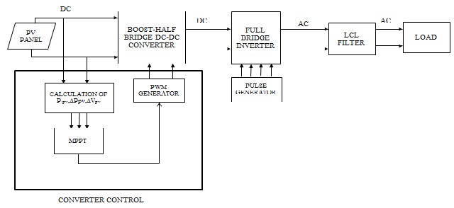
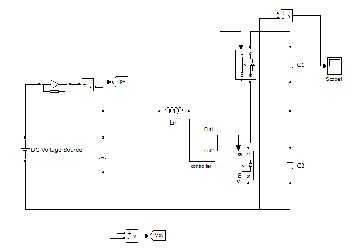
Fig.1 Block Diagram of Boost Half Bridge Micro Inverter
IJSER
A new MPPT control is proposed in this paper. The
main difference between the proposed system and other
techniques used in the past is, in this system the PV panel is directly controlled by the DC-DC converter [2]. This reducing the complexity of the system. The system consist of three important parts they are PV panel, boost half bridge inverter and full bridge inverter as shown in fig.1. The PV array output power delivered to a load can be maximized by using MPPT control systems. From the PV panel voltage and current feedback are taken and given to MPPT controller. The controller utilizes those voltage and current from the solar panel and by using MPPT algorithm it calculates switching pulses. The gate pulses are given to the boost converter by the calculated switching pulses through PWM generator.
The converter uses ramp change and variable step size algorithm. In the ramp change algorithm it will change the tracking position in the gradually speed to the maximum power point. The speed of the tracking is same when the MPP is far away and MPP is nearer. This makes the system to respond slowly.
The variable step size algorithm track the MPP in two
different speeds. The speed of the tracking will vary
according to the distance of MPP. This makes the system adaptive and the efficiency of the system also increases. In this proposed system, output of both the system is compared and given to the inverter side.
The PV energy applications can be divided into two
categories they are:
1. A standalone system
2. A Grid connected system
The standalone system requires battery bank to store the PV energy and is suitable for low power system. But the grid connected does not require any battery bank because it is directly connected to the grid. And also it is the primary method for grid connected system [5].
The boost half bridge micro inverter composed of two stages they are in the front end it has DC-DC converter and in the other end it has full bridge inverter.
The input to the converter is given by the solar panel
according to the changing sun irradiance. The conventional boost converter is modified by splitting the output DC capacitor into two separate ones. Cin and Lin are the input capacitor and boost inductor. As half bridge converter the centre taps of the MOSFETs (S1, S2) and the output of the capacitors are connected to the primary of the transformer. The low voltage side DC link voltage is Vdc1 and high voltage side DC link voltage is Vdc2. The combination of two diodes (D1, D2) and capacitors (C3, C4) act as a voltage doubler and is incorporated to rectify the transformer secondary voltage to the inverter DC link [15]. A full-bridge inverter composed of four MOSFETs (S3-S6) using synchronized PWM control. Third order LCL filter composed of Lo1, Lo2, and C0 are used to reduce the harmonics and supply the current with unity power factor. The output is given to the grid.
IJSER © 2013
International Journal Of Scientific & Engineering Research, Volume 4, Issue 12, December-2013
ISSN 2229-5518
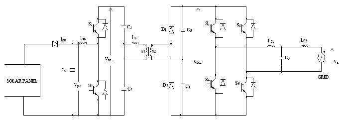
Fig.2 Circuit Diagram of Boost Half Bridge Micro Inverter
2079
Table I gives the parameter details of the boost half bridge converter. The MPPT block in a PV converter system
An individual solar array can work efficiently when it operate at its maximum power point. A novel maximum- power-point-tracking (MPPT) controller for a photovoltaic
IJSER
periodically change the tracking reference of PV voltage or
PV current or the converter duty cycles [16]. The boost half
bridge converter is controlled by the switches S1 and S2 through duty cycles. Duty cycle of S1 denoted by d1 and switching period is denoted by Tsw1. To obtain optimal efficiency of boost-half-bridge converter ZVS techniques are considered and for simplicity hard switching is adopted [16]. The voltages are calculated by the below formula.
(1 d1 )
(PV) energy conversion system is presented. Using the slope of
power versus voltage of a PV array, the proposed MPPT
controller allows the conversion system to track the maximum
power point very rapidly [20]. There are various types of MPPT algorithms are used. Some MPPT techniques calculate the step size through online relying through instantaneous
ΔPpv, ΔVpv. This makes the system more adaptive but is vulnerable to noises.
The ramp change algorithm gives minimum voltage to the![]()
Vc1
Vpv
d1
Vc2 Vpv
converter because of its large step. To overcome this problem
PV operating points are calculated in three different zones in
variable step size technique. The step size is large when the
Vc3
![]()
n(1 d1 )
d1
Vpv
Vpv
Vc4
nVpv
nVpv
Maximum Power Point (MPP) is far away but when MPP is nearer then fine tuning small step size is used. Variable step size technique is one of the most efficient methods to track the maximum power point. In variable step size method by![]()
Vdc1
1
![]()
Vdc2
1
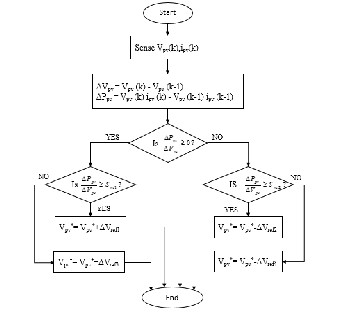
sensing ΔPpv, ΔVpv the tracking step sizes are calculated by the given algorithm. It is represented in the flow chart in fig.3.
function Vr = fcn( Q )
if (Q >= 0)
BOOST HALF BRIDGE CONVERTER PARAMETERS
if (Q >= 4) Vr=Q+0.3;
Else
end else
Vr=Q+0.1;
if (Q <= -10)
Vr=Q-0.3;
else
end end
Vr=Q-0.1;
IJSER © 2013
International Journal Of Scientific & Engineering Research, Volume 4, Issue 12, December-2013
ISSN 2229-5518
2080
BOOST HALF BRIDGE CONVERTER PARAMETERS
Switching Frequency | 10.8 KHZ |
DC Link Voltage | 370V |
Filter Inductor(Lo1,L02) | 8.5mH |
Filter Capacitor(Co) | 330nF |
The table II consist of frequency, link voltage and gives inductor and capacitor values.
Fig.3 Flow Chart for VSS Algorithm
Using an LCL filter in a grid-connected inverter system has been recognized as an attractive solution to reduce current harmonics around the switching frequency, improve the system dynamic response, and reduce the total size and cost. Typically, a un damped LCL filter exhibits a sharp LC resonance peak, which indicates a potential stability issue for the current regulator design. Hence, either passive damping or active damping techniques can
be adopted to attenuate the resonance peak upto 0 dB. The
IJSER
Full bridge inverter consists of four MOSFET switches S3, S4, S 5, and S6. Between the converter and the inverter an isolation transformer is used for safety. The isolation transformer helps to protect the converter circuit while during the fault in the inverter. The output current of the inverter is filtered by a first order low pass filter on the circuit to eliminate high frequency noises.
The filter output has minimized noises and harmonics
and it is given to the grid.
current sensor is placed at the inverter side instead of the grid side [15].
The current controller has the following features:
1. High power factor.
2. Current harmonic distortion caused by the grid voltage non-ideality are minimized.
3. Outstanding current regulation.
4. Fast dynamic response in both load and solar radiation changes.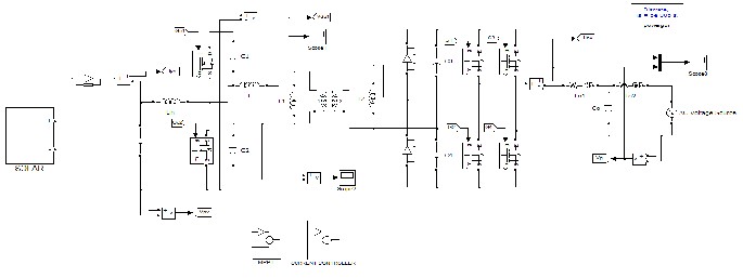
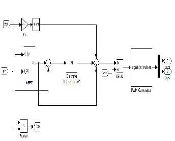
Fig.4 Boost Half Bridge Micro Inverter Simulation Diagram
IJSER © 2013
International Journal Of Scientific & Engineering Research, Volume 4, Issue 12, December-2013
ISSN 2229-5518
(a)
2081
(a)
(b)
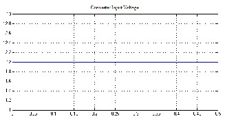
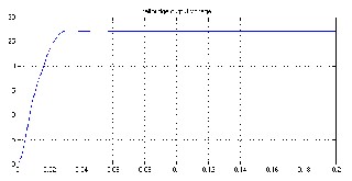
Fig.6 Simulation Results (a) Input Voltage (b) Converter
Output Voltage
(b)
Fig.5 Simulation Diagram (a) Converter Simulation (b) MPPT Controller
The fig.4 shows the overall circuit diagram of the photovoltaic Micro Inverter System. It consist of boost half bridge converter and inverter. The fig.5.shows the simulation diagram of converter and Variable Step Size MPPT control. The Variable Step Size algorithm is implemented in the MPPT block.
The MPPT block takes the voltage and current feedback
from the solar and helps to execute the program.
The simulation results gives the output of the boost half bridge DC-DC converter. The converter takes the input as
12V from the solar panel and gives the step up voltage as
28V. Fig.6. shows the input and the output voltage of the converter.
A boost-half-bridge micro inverter for grid-connected PV systems has been presented. The number of semiconductor devices has been reduced. The reduced devices, circuit simplicity, and easy control, the boost-half- bridge PV micro inverter possesses features of low cost and high reliability. The boost- half-bridge DC–DC converter has a high efficiency (97.0% – 98.2%) over a wide operation range. And also the current injected to the grid is regulated precisely and stiffly. The ramp-changed reference generated by the customized MPPT method for the PV voltage regulation guarantees a correct and reliable operation of the PV micro inverter system. Fast MPP tracking speed and a high MPPT efficiency (>98.7) is achieved by the variable step-size technique.
[1] Changwoo Yoon, Joongeun Kim, and Sewan Choi (2011)
―Multiphase DC–DC Converters Using a Boost-Half-Bridge Cell for High-Voltage and High-Power Applications‖ IEEE Transactions on Power Electronics, Vol. 26, No. 2, pp.381-388.
[2] Eftichios Koutroulis, Kostas Kalaitzakis (2001) ―Development of a Microcontroller-Based, Photovoltaic Maximum Power Point Tracking Control System‖ IEEE Transactions on Power Electronics, Vol. 16, No. 1, pp.46-54.
IJSER © 2013
International Journal Of Scientific & Engineering Research, Volume 4, Issue 12, December-2013
ISSN 2229-5518
2082
[3] Fang Z. Peng, Hui Li, Gui-Jia Su, and Jack S. Lawler (2004) ―A New ZVS Bidirectional DC–DC Converter for Fuel Cell and Battery Application‖ IEEE Transactions on Power Electronics, Vol. 19, No.
1, pp.54-65
[4] Huili, Fang Z. Peng (2004) ―Modeling Of A New ZVS Bi- Directional DC-DC Converter‖ IEEE Transactions on Aerospace and Electronic Systems Vol. 40, No. 1, pp.272-283.
[5] II-Song Kim, Myung-Bok Kim, and Myung-Joong Youn (2006) ― New Maximum Power Point Tracker Using Sliding-Mode Observer for Estimation of Solar Array Current in the Grid- Connected Photovoltaic System‖ IEEE Transactions on Industrial Electronics, Vol. 53, No. 4, pp.1027-1035.
[6] Kai Zhang, Yong Kang, Jian Xiong, and Jian Chen (2003) ―Direct
Repetitive Control of SPWM Inverter for UPS Purpose‖ IEEE
Transactions on Power Electronics, Vol. 18, No. 3, pp.784-792.
[7] Kun Ding, XinGao Bian, HaiHao Liu, and Tao Peng (2012) ―A
MATLAB-Simulink-Based PV Module Model and Its application under Conditions of Non-uniform Irradiance‖ IEEE Transactions on Energy Conversion, Vol. 27, No. 4, pp.864-872.
[8] Luowen Li, Lihua Xie, Wei-Yong Yan, and Yeng Chai Soh (1999)
―Design Of Low-Order Linear-Phase IIR Filters Via Orthogonal Projection‖ IEEE Transactions on Signal Processing, Vol. 47, No. 2, pp.448-457.
[9] Nobuyuki Kasa, Takahiko Iida, and Liang Chen (2008) ―Flyback Inverter Controlled by Sensorless Current MPPT for Photovoltaic Power System‖ IEEE Transactions on Industrial Electronics, Vol.
52, No. 4, pp.1145-1152.
[10] Paolo Mattavelli, and Fernando Pinhabel Marafao, (2004)
Photovoltaic Module System‖ IEEE Transactions on Power
Electronics, Vol. 21, No. 5, pp.1264-1272.
[19] Trishan Esram, and Patrick L. Chapman, Senior Member (2007)
―Comparison of Photovoltaic Array Maximum Power Point Tracking Techniques‖ IEEE Transactions on Energy Conversion, Vol. 22, No. 2, pp.439-449.
[20] Yeong-Chau Kuo, Tsorng-Juu Liang, and Jiann-Fuh Chen (2001)
―Novel Maximum-Power-Point Tracking Controller for Photovoltaic Energy Conversion System‖ IEEE Transactions on Industrial Electronics, Vol. 48, No. 3, pp.594-601.
[21] Yongqiang Ye, Keliang Zhou, Bin Zhang, Danwei Wang, and
Jingcheng Wang (2006) ―High-Performance Repetitive Control of PWM DC-AC Converters With Real-Time Phase-Lead FIR Filter‖ IEEE Transactions on Circuits And System, Vol. 53, No. 8, pp.768-772.


IJSER
―Repetitive-Based Control for Selective Harmonic Compensation in Active Power Filters‖ IEEE Transactions on Industrial Electronics, Vol. 51, No. 5, pp.1018-1024.
[11] Quan Li, and Peter Wolfs (2007) ―A Current Fed Two-Inductor Boost Converter with an Integrated Magnetic Structure and Passive Lossless Snubbers for Photovoltaic Module Integrated converter Applications‖ IEEE Transactions on Power Electronics, Vol. 22, No. 1, pp.309-321.
[12] Quan Li, and Peter Wolfs (2008) ―A Review of the Single Phase Photovoltaic Module Integrated Converter Topologies with Three Different DC Link Configurations‖ IEEE Transactions on Power Electronics, Vol. 23, No. 3, and pp.1320-1333.
[13] Rong-Jong Wai, and Wen-Hung Wang (2008) ―Grid-Connected Photovoltaic Generation System‖ IEEE Transactions on Circuits and Systems, Vol. 55, No. 3, pp.953-964.
[14] Shuai Jiang, Dong Cao, Yuan Li, Member, Jianfeng Liu, and Fang
Zheng Peng (2012) ―Low-THD, Fast-Transient, and Cost- Effective Synchronous-Frame Repetitive Controller for Three- Phase UPS Inverters‖ IEEE Transactions on Power Electronics, Vol. 27, No. 6, pp.2994-3005.
[15] Shuai Jiang, Dong Cao, Yuan Li, and Fang Zheng Peng, (2012)
―Grid-Connected Boost-Half-Bridge Photovoltaic Microinverter System Using Repetitive Current Control and Maximum Power Point Tracking‖ IEEE Transactions on Power Electronics, Vol. 27, No. 11, pp.4711-4722.
[16] Soeren Baekhoej Kjaer, John K. Pedersen, and Frede Blaabjerg,
(2005) ―A Review of Single-Phase Grid-Connected Inverters for
Photovoltaic Modules‖ IEEE Transactions on Industry
Applications, Vol. 41, No. 5, pp.1292-1306.
[17] Tomas Hornik and Qing-Chang Zhong, (2011) ―A Current- Control Strategy for Voltage-Source Inverters in Microgrids Based on H∞ and Repetitive Control‖ IEEE Transactions on Power Electronics, Vol. 26, No. 3, pp.943-952.
[18] Toshihisa Shimizu, Keiji Wada, and Naoki Nakamura (2006)
―Flyback-Type Single-Phase Utility Interactive Inverter With
Power Pulsation Decoupling on the DC Input for an AC
Electrical and Electronics Engineering from
Periyar University, Salem in 2002 and M.E.
degree in Power Electronics and Drives from Anna University, Chennai in 2006.He is currently pursuing his doctoral degree in Anna University, Chennai. He is working as an Assistant Professor in the Department of Electrical and Electronics Engineering at K.S.Rangasamy College of Technology
(Autonomous Institution). He is a Life member of ISTE and ISEEE. His research interests are renewable energy sources, inverters, converters.

1987 respectively. He worked as a Lecturer in the Department of Electrical Engineering in Government College of Engineering, Salem from
1968, as an Assistant professor in Government College of Technology, Coimbatore from 1983 and as Principal at K.S.Rangasamy College of Technology from 1995. He is currently working
as a Dean in the Department of Computer Science and Engineering at K.S.Rangasamy College of Technology (Autonomous Institution).His research interest includes Mobile Computing, Soft Computing, Computer Architecture and Data Mining. He is a senior member of ISTE, IEEE and CSI.
IJSER © 2013