rapid and continuous changes of transmission line
Where
International Journal of Scientific & Engineering Research, Volume 5, Issue 3, March-2014 93
ISSN 2229-5518
Line Loadability Improvement by using TCSC
under Network Contingencies
D.Naga Krishna Sumanth, D.Ragaleela, Dr.Ch.Padmanabha Raju
The Thyristor Controlled Series Capacitor (TCSC) is one of the most effective Flexible AC Transmission System (FACTS) devices. It offers smooth and flexible control of the line impedance with much faster response compared to the traditional control devices. It may be used to enhance system performance by controlling the power flows in the network and to alleviate /eliminate the overloads on the transmission lines under network contingencies. The Newton-Raphson ac power flow method was used to perform the above studies. The performance of the proposed algorithm has been tested for IEEE-14 bus system. Programming of the power flow studies is carried out by using MATLAB.
—————————— ——————————
In current day power system, there will be an increase in number of situations where power flow equations have either no real solution (unsolvable case) or solution with violating operating limits such as line limit (insecure case), particularly, in contingency analysis and planning applications. Since insecure cases often represent the most severe threats to secure system operation. Few papers have dealt with the power system insecurity and possible control to bring the system back to secure state [1]. The possibility of controlling power flow in an electric power system without generation rescheduling or topological changes can improve the performance considerably [2].
————————————————
• D.Naga Krishna Sumanth, M.Tech Student, Department of EEE, Prasad V. Potluri Siddhartha Institute of Technology, Vijayawada, Andhra Pradesh, India
E-mail: nagakrishnasumanth@gmail.com
• D.Ragaleela, Sr. Assistant Professor, Department of EEE, Prasad V. Potluri Siddhartha Institute of Technology, Vijayawada, Andhra Pradesh, India
E-mail: raga_233@yahoo.co.in
• Dr.Ch.Padmanabha Raju, Professor, Department of EEE, Prasad V.Potluri Siddhartha Institute of Technology, Vijayawada, Andhra Pradesh, India
Email: pnraju78@yahoo.com
The primary requirement of power system is to meet the demand that varies continuously. The dispatchers are required to operate the system closer to its thermal limits and increase its transit capacity of power. The control of the power system can be obtained through the implementation of devices based on power electronic with high-speed response, recently developed and called FACTS
[3]. The TCSC is one of the most promising components of FACTS. Thyristor Controlled Series Capacitor is one such device, which offers smooth and flexible control of the branch impedance with much faster response compared to the traditional control devices [4]-[6].
The electric power flow problem is the most
studied and documented problem in power engineering.
Load flow calculations provide power flows and voltages
for a specified power system subject to the regulating
capability of generators, tap changing transformers and as
well as specified net interchange between individual operating systems. This information is essential for the continuous evaluation of the current performance of a power system and for analyzing the effectiveness of alternative plans for system expansion to meet increased load demand.
The power flow problem is formulated as a set of
nonlinear equations. Many calculation methods have been
proposed to solve this problem. Among them, Newton-
Raphson method is a very successful method. The system
conditions with large angles across lines (heavily loaded network) and with special control that strongly influence active and reactive power flows, Newton-Raphson method may be required [7].
Therefore, when the AC power flow calculation is
needed in systems with FACTS devices, Newton-Raphson method is suitable for power flow calculation in the system with TCSC when high accuracy is required [8]-[9]. In case of a contingency, TCSC can be used effectively used in maintaining system security by eliminating or alleviating overloads along the selected network branches and the effects of the TCSC utilization under single line contingency are explored here [10]. In this paper, we concentrate on the enhancement of system static security against single contingencies via the use of TCSC.
IJSER © 2014 http://www.ijser.org
International Journal of Scientific & Engineering Research, Volume 5, Issue 3, March-2014 94
ISSN 2229-5518
X = X C X L
(6)
Thyristor Controlled Series Capacitor (TCSC) allows
rapid and continuous changes of transmission line
Where![]()
LC X
C − X L
2
impedance. Fig.1 shows the TCSC module connected in series with the transmission line [4].![]()
C = X C + X LC , C =
1 π 2
![]()
4 X LC (7)
X L π
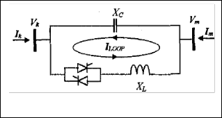
The admittance matrix of the TCSC module shown in Fig .1
is
Ik = jBkk
jBkm Vk
(8)
Im
jBmk
jBmm Vm
1
Fig.1: TCSC model
The TCSC is incorporated into the load flow calculations by![]()
Bkk = Bmm = BTCSC (1) = − (9)
X TCSC
1
![]()
km mk TCSC (1)
TCSC (1)
When TCSC is used to control power flow in the line k-m, the set of power flow equations are given by
setting the total line reactance to
∂pk
∂pk
∂pk
∂pk
∂pk
![]()
![]()
![]()
![]()
![]()
X TOT = X + X TCSC
(1)
∂δk
∂ Vk
∂δm
∂ Vm
∂X TCSC
∆P
∂Qk
∂Qk
∂Qk
∂Qk
∂Qk
The basic equation is,![]()
![]()
k ∂δ ∂ V
![]()
![]()
∂δ ∂ V
![]()
∂X
∆δk
∆
![]()
![]()
k k m m TCSC ∆ V
Z = R
+ jX
V
= TCSC (1)
(2)
Qk
∂p ∂p ∂p ∂p
∂p k
![]()
Iline
∆Pm = ∂δ ∂ V
![]()
![]()
∂δ ∂ V
∂X ∆δm
TCSC (1)
TCSC (1)
TCSC (1)
![]()
m m m m m
![]()
![]()
![]()
![]()
k k m m TCSC
Where (bold type indicates complex quantities).
∆Qm
∂Q ∂Q ∂Q ∂Q
∂Q ∆ Vm
∆
m m m m m ∆X
VTCSC (1) is the fundamental frequency voltage across the
Pkm
![]()
![]()
![]()
![]()
∂δ ∂ V
∂δ ∂ V ∂X
TCSC
TCSC module,Ilineis the fundamental frequency line current
k k m m TCSC
and ZTCSC (1) is the TCSC impedance. The voltage VTCSC (1) is equal to the voltage across the TCSC and equation (2) can
∂pkm
![]()
∂δ
![]()
∂pkm
∂ Vk
∂pkm
![]()
∂δm
![]()
∂pkm
∂ Vm
∂pkm
![]()
∂X TCSC
be written as,
(11)
ZTCSC (1)
− jX I
![]()
= c cap (1)
Iline
(3)
Where, the elements of additional row and column of the modified Jacobean can be written as:
If the external power network is represented by an idealized current source, as seen from the TCSC terminals, this current source is equal to the sum of the currents
∂Pkm =
∂δk
− VkVm
![]()
X TCSC
cos(δk − δm )
(12)
flowing through the TCSC capacitor and inductor. The
∂Pkm =
![]()
VkVm
δ − δ
(13)
TCSC impedance can then be expressed as,![]()
2
TCSC TCSC
sin(
k m )
ZTCSC (1)
− jX (I − I )
![]()
= C line TCR (1)
Iline
(4)
∂Pkm
![]()
∂δ
![]()
= VkVm
X
cos(δk − δm )
(14)
In this paper, TCSC is represented by its fundamental
m TCSC
frequency impedance module. TCSC power flow equations,![]()
![]()
∂Pkm =
− VkVm
sin(δ − δ )
(15)
with respect to firing angle, are incorporated into an existing Newton-Raphson algorithm. The fundamental
2 k m
TCSC TCSC
TCSC equivalent reactance as a function of TCSC firing
angle α [4], is given as
∂Pkm =
∂ ![]() Vk
Vk ![]()
![]()
− Vk
X TCSC
sin(δk − δm )
(16)
( ( )
( ( )))
2 ( ) (
( ( )) ( ))
X TCSC (1) = − jX C + C1 2 π − α + sin 2 π − α − C2 cos
![]()
![]()
π − α ω tan ω π − α − tan π − α
![]()
∂Pk =
![]()
VkVm
sin(δ − δ )
(17)
(5)
2 k m
TCSC TCSC
IJSER © 2014 http://www.ijser.org
International Journal of Scientific & Engineering Research, Volume 5, Issue 3, March-2014 95
ISSN 2229-5518
![]()
![]()
∂Qk = − Vk −
![]()
VkVm
cos(δ − δ )
(18)
∂X X 2
X 2 X k m
TCSC TCSC TCSC
![]()
![]()
∂Qm = − Vm −
![]()
VkVm
cos(δ − δ )
(19)
∂X X 2
X 2 X k m
TCSC TCSC TCSC
The mismatch vector ∆Pkm = Pkm ( reg ) − Pkm ( cal ) is the active
The objective of the approach is to alleviate the
overloads on the transmission lines by minimizing the
power mismatch for the TCSC branch.
Pkm ( reg )
is the
apparent value of power by incorporating the TCSC. In this
required power flow in the TCSC branch. Now by using the
case, the load on the power system is 259.1 MW. The power
mismatch it can be modified as X ( p +1) = X p
+ ∆X p
where ∆X p
TCSC TCSC TCSC
is the incremental change in TCSC reactance
flow in the branch 7-5 is 33.72 MVA (without TCSC) and
the line limit is 32 MVA.
and P shows the Pth iteration.
Step 1: Consider each series FACTS device as a separate
branch in the network.
Step 2: Initialize the unknown state variables to guessed
values.
Step 3: Apply contingency analysis procedure to the bus
network.
Step 4: Find the security violated lines.
Step 5: Place the TCSC in the security violated line and
then solve the load flow problem with TCSC.
Step 6: If convergence is reached then go to next step
otherwise go to step 3.
Step 7: Stop
The effectiveness of the proposed method is tested on IEEE 14-bus system. The 14-bus test system consists of five generator buses at buses 1, 2, 3, 4, 5. Buses 6, 7, 8, 9, 10, 11, 12,
13, 14 are load buses. The system has got 20 transmission
lines. In the study the power handling ability of a line is
limited by its thermal loading limit. This limit is used to
check for any violation in the line limits. The important contingencies, which are actually causing problems to system security, are considered in the study. The power flow solutions in each of these contingencies are computed in MATLAB. For the intended work, the mathematical model of TCSC is incorporated in MATLAB. The results are presented in the paper to demonstrate the effectiveness of the proposed method.
In this system, three typical load patterns have been taken into account, which are referred as Case1, Case2 and Single line contingency as shown in the Table-1.The power
flow of the transmission lines which are violated their load limits are mentioned in the tables of different cases, others which are not represented in these tables are within the load limits.
TABLE-1: TYPICAL LOAD PATTERNS
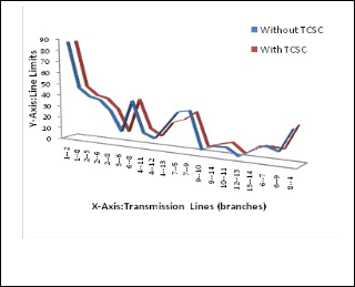
TABLE-2: COMPARISON OF POWER FLOW S WITH BASE LOAD
BRANCHES | LINE FLOW LIMIT (MVA) | LINE FLOWS(MVA) [without TCSC] | LINE FLOWS(MVA) [With TCSC] | |
FROM NODE | TO NODE | LINE FLOW LIMIT (MVA) | LINE FLOWS(MVA) [without TCSC] | LINE FLOWS(MVA) [With TCSC] |
7 | 5 | 32 | 33.72 | 25.7 |
Fig.2: With Base load
.
From the Table-2, we observe that the line 7-5 gets overloaded and the power flow in that branch is 33.72
MVA. So by placing TCSC in line 7-5 we can decrease the
power flow to 25.7 MVA without crossing the line limits.
The Fig.3 shows the line flow limits on Y-axis in MVA and
the X-axis represents transmission lines of the network.
The equivalent reactance of the TCSC required for reducing
the overload in line 7-5 is 0.2469 (p.u). In Fig.2 the red line indicates the line flows when the TCSC is placed in the network and the blue line indicates the line flows when the TCSC is not present in the network, From the Fig.2 we can
IJSER © 2014 http://www.ijser.org
International Journal of Scientific & Engineering Research, Volume 5, Issue 3, March-2014 96
ISSN 2229-5518
observe that the power flow is reduced and it is within the acceptable limits for the 7-5 line by incorporating TCSC.
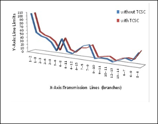
In this case load on the power system is 285.01 which represent 10% increment on base load. The power flow in the branch 7-5 is 34.39 MVA (without TCSC) and the line limit is 32 MVA. Thus, the system needs controlling of power in the line 7-5 i.e., well below their thermal rating. So, we place the TCSC in the line 7-5 for reducing the overload. After placing the TCSC in the line 7-5, the overloaded line carries the power flow well below their power rating shown in Table-3. In the Fig.3 on the X-axis, the numbers 1-2, 1-8, 2-3, 2-6, 2-8, 3-6, 6-8, 4-11, 4-12, 4-13, 7-
5, 7-9, 9-10, 9-14, 10-11, 12-13, 13-14, 6-7, 6-9, 8-4 are the branches and the Y-axis indicates line limits. From the Fig.3 it is observed that the line limit at transmission line 7-5 violates its specified maximum limit of 32 MVA. With proper setting of TCSC, the overloads are eliminated / alleviated. The equivalent reactance of the TCSC required for reducing the power flow in 7-5 is 0.30 p.u.
TABLE-3: COMPARISON OF POWER FLOW S WITH INCREMENT LOAD
(without TCSC) and the line limit is 32 MVA. The power flows are represented in Table-5. By placing the TCSC in the
7-5 branch and setting of TCSC parameters the power flow was controlled to 28.56 MVA and the load is transferred to other lines without violating the line limits. The TCSC parameters are mentioned in the table-4.
TABLE-4: LOCATION AND PARAMETER SETTING OF THE TCSC
BRANCHES | Initial TCSC Parameter value (p.u) | TCSC reactance (p.u.) |
7-5 | -0.015 | 0.2181 |
TABLE-5: COMPARISON OF POWER FLOW S WITH SINGLE LINE CONTINGENCY
In Fig.4 the Y-axis indicates the line limits and the X-axis represents the branches of transmission lines. From the Fig.5 we observe that in the line 7-5 power flow violates the limits and the power is reduced after placing of the TCSC.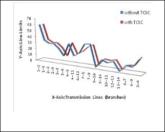
Fig.3: With 10% incremental of load
.
In this case, the transmission line 4-13 is removed from the network and the load on the power system is 259.1
MW. The power flow in all the branches are within the acceptable limits except the 7-5 branch i.e. 35.02 MVA
Fig.4: With single contingency
IJSER © 2014 http://www.ijser.org
International Journal of Scientific & Engineering Research, Volume 5, Issue 3, March-2014 97
ISSN 2229-5518
This paper has presented a Newton-Raphson load flow
method to solve power flow problems in power system with placement of the TCSC. It is simple, efficient and reliable method for solving power flow problem with increase in network load and under occurrence of contingencies. The proposed method is tested on IEEE-14 bus system and the simulation results are reported.
It was observed that the proposed algorithm is also
suitable for large systems with better range of power control. The results show the effectiveness and robustness of proposed method over a wide range of power flow variations in the transmission system.
[1] S.N.Singh and S.C.Srivastava, “Corrective action planning to achieve a feasible optimal power flow solution,” IEE Proc. Part-C, vol. 142, no. 6, November 1995, pp. 576 -582.
[2] F.D.Galiana, K.Almeida, M.Toussaint and B.T. Ooi, “Assessment and control of the impact of FACTS devices on power system performance,” IEEE Trans on Power System, vol. 11 , no. 4, Nov.
1996, pp. 1931-1936.
[3] N.G.Hingorani, “Flexible AC Transmission,” IEEE vol.30, no.4, April 1993.
[4] C.R.Fuerte-Esquivel, E.Acha, H.Ambriz-perez, “A Thyristor Controlled series compensator model for the power solution of practical Power Networks,” IEEE transactions on Power Systems, vol.15, no.1, February 2000.
[5] S.N.Singh, “Location of FACTS Devices for Enhancing Power Systems’ Security,” Large Engineering Conference on Power Engineering 2001, pp.162-166.
[6] E.V.Larsen, “Characteristics and rating considerations of Thyristor controlled series compensation,” IEEE transactions on power delivery, vo1.9, no.2, April 1994, pp. 992-1000.
[7] Stott B, “Review of Load-flow Calculation Methods,” IEEE Proceedings, vol.62, July 1974, pp. 916-929.
[8] Y.Lu and A.Abur, “Static security enhancement via optimal utilization of thyristor controlled series capacitors,” IEEE Trans. Power Systems vol.17, no.2, May.2002, pp. 324-329.
[9] K.ShanmukhaSundar, and H.M.Ravikumar, “Enhancement of Power System Performance using TCSC,” Power System Technology and IEEE Power India Conference, 2008, pp.1-7.
[10] G.Raman, D.S.Babu, P.S.Venkataramu and M.S.Maharaja, “Sensitivity factor based improvement studies incorporating facts devices under line outage Contingency” International conference on power, energy and control-2013, pp.64-68.
BIOGRAPHIES
D.Naga Krishna Sumanth is pursuing his
M.Tech (Power System Automation and Control) in the Department of Electrical & Electroncics Engineering, from P.V.P.Siddhartha Institute of Technology, Vijayawada, Andhra Pradesh, India. He obtained B.Tech degree in Electrical and Electronics Engineering from J.N.T.U Hyderabad in the year 2008.

D.Raga Leela is currently working as Sr.Assistant Professor in the Department of Electrical & Electronics Engineering, P.V.P.Siddhartha Institute of Technology, Vijayawada, Andhra Pradesh, India. She obtained M.Tech from Nagarjuna University, Guntur and doing Ph.D in the area of power systems at J.N.T.University, Kakinada. Her areas of interest are Power System Security, OPF techniques and FACTS.

Dr.Ch.Padmanabha Raju is currently working as Professor in the Department of Electrical & Electronics Engineering, P.V.P.Siddhartha Institute of Technology, Vijayawada, Andhra Pradesh, India. He obtained Ph.D from J.N.T.University, Kakinada .His areas of interest are Power System Security, OPF techniques, Deregulation and FACTS.
IJSER © 2014 http://www.ijser.org