International Journal of Scientific & Engineering Research, Volume 4, Issue 7, July-2013 954
ISSN 2229-5518
Information Systems modelling from
Flowcharts to process model
Himani Sharma, Deepak Kumar Sharma
Abstract—Business process modelling has always been at the core of both organizational design and information system. Business process modelling aims for the transformation of business perspective of enterprise into IT perspective, which require business process model of the possible set of business process operation of the enterprise. Business process model provides the comprehensive understanding of a process through which an enterprise can be analyzed and integrated, which necessitate the importance of modelling correctly. W ith the existence of variety of business process modelling language we have to perform the evaluation of various business process modelling languages for accessing the acceptability criteria according to specialized needs of the enterprise business process operation as each and every modelling language has its own perspective and represent different features of the processes. This paper presents the review of five popular modelling languages which are widely used today.
Index Terms—business process management, business process, business process modelling, business process modelling languages.
————————————————————
1 INTRODUCTION
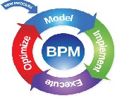
Business process management (BPM) is a systematic approach towards the definition, execution, management and refine- ment of business processes. The aim of BPM is to support ef- fective management of business processes within an organiza- tion through the uses of specialized tools and software’s .The business processes are the core of BPM as it helps in improv- ing the overall business process of an enterprise. A business process [7] can be defined “as a collection of activities that takes one or more kinds of input and creates an output that value to the customer”. Various phases of BPM have shown in figure1 and described as:
Figure 1: Business Process Management Lifecycle [3]
• Model: The first phase of BPM is business process model- ling. In this phase, the analysts create an analytical process model with the help of a modelling tool to specify ordered tasks of a business process [21]. Business process model are high-level abstraction of the business process they cannot directly executed as they lack the technical infor- mation such as binding of IT services and data formats for each task. Therefore, an analytical model must be an exe-
————————————————
• Himani Sharma is currently pursuing masters degree program in cmputer science engineering in M.D University, India. E-mail: himanini.sharma24@gmail.com
• Deepak Kumar Sharma is assistant professor (Computer Science & Engineering) in
MRCE, Faridabad, M.D University, India. E-mail: masterdeepak12@gmail.com
cutable process model, which is workout in next phase.
• Implement: In this phase, the high-level abstract process model transforms into a process model enriched by IT en- gineers. This model will deploy for execution in a process engine [21].
• Execute: After process deployment, the process engine executes process instances by navigating through the con- trol flow of the process model. This phase is concern with the interpretation of the instructions, which are created during the implement phase to manage the flow of work [21].
• Optimize: The goal of this phase is to revisit the original process and to identify the changes that can improve the overall process. This phase resolve deficiencies or area of improvement that have been identified previously.
However, to date model phase is of great interest of various researchers as they believe that a successful systems start with proper understanding of business process of an enterprise. Business processes are key factors for integrating an enter- prise, but having a proper understanding of them is not as simple as it seems to be. Here, business process modeling helps and try to conceptualize the characteristics of business processes in Graphical notations named as Business Process Modelling Languages. The aim of this paper is to review the various popular business process modelling techniques each with their strength and weaknesses and a comparative analy- sis.
This paper is organized in the following sections. Section 2 describes the literature review. The Section 3 describes the main review of various modelling languages. Section 4 pre- sents comparative analysis and Section 5 concludes the re- search.
IJSER © 2013 http://www.ijser.org
International Journal of Scientific & Engineering Research, Volume 4, Issue 7, July-2013 955
ISSN 2229-5518
2 LITERATURE REVIEW
The business process models are constructed using particular modeling techniques for proper understanding and analysis of the system. The starting of this research was done by Kettinger et al. in (1997a)[9],who presented a list of some related busi- ness process modeling method, tools and technique used in business process reengineering, but detailed description was not there. Detailed and more thorough description was pre- sented by Kettinger et al. in next volume (1997b) [10]. Later, Phalp et al. (1999)[17] distinguished between two uses of busi- ness process models, one for traditional software development and another for restructure business processes. Then Ruth Sara Aguilar-Savlen [18] in 2004 presented a review of busi- ness process modeling tools and technique, and proposed a framework based on their purpose for classifying different business process modeling languages, which provides guid- ance to practitioners. Anna GunhildNysetvold and John Krogstie in 2005[1] presented a generic framework based on quality model for the evaluation of three different modeling language .The work illustrated the practical utility of the over- all framework, where language quality features were looked upon so as to enable the creation of models of high quality. It also illustrates the need for specializing this kind of general framework based on the requirements of the specific organiza- tion. Laden Aldin and Sergio de Cesare [11] in 2009 presented an analysis of popular modeling languages based on a com- parative framework, which includes five basic criteria such as flexibility, ease of use, understandability, simulation, support and scope. The proposed work in the paper served as the basis for evaluating further modeling techniques and generating selection procedures. Ryan K L KO et al. in 2009[19] done an extensive literature review of standard modeling notations and identifies the strength and limitations of the common modeling standard . Hafedhmili et al. in 2010[6] presented an overview of business process and different modeling lan- guages with the categorization of various languages to a fami- ly with the description of the representative language of that family.
3 BUSINESS PROCESS MODELING LANGUAGES
Business process modeling is concerned with the model phase of business process management and plays a vital role in business process management discipline. It provides compre- hensive view of business processes of an integrated enterprise and helps in overall understanding and analysis of the busi- ness process of an enterprise. In this section review of various modeling languages with their strength and weaknesses is being presented.
3.1. Flowcharting
Flowchating is a first graphical representation technique from the past 1960’s [20],which was initially intended to provide computer program logic representation but due to its generic nature it is also adopted in business process modelling for representing process model. In business process modelling flowcharts are used to illustrate the control flow of a process. Flow charts represent business process as a sequential activity
and have four key constructs such as activity, decision, start/end and sequence (arrow). Relationships are represented by sequence which represents control flow from one element to another and every element in flowchart is directly or indi- rectly connected to one another.
Strengths:
• Flowcharts can easily show overall structure of a sys- tem, can trace flow of information and can highlight key processing and decision points of a system [5].
• Flowcharts are flexible as they are simple to update and helps in easy identification of bottlenecks or inef- ficiencies where process can be improved [18].
• Flowcharts are also very simple to use as limited set of simple notations exits for this technique.
• Communication ability of flowcharts is really good as it is easy to understand the process they describe.
Weakness
• It is too much flexible as boundary of process may not be clear.
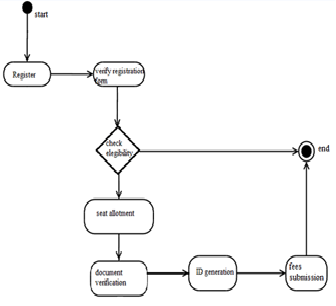
Example: In figure 2 flowchart for admission procedure is
shown.
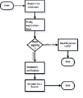
Figure2: Flowchart for admission procedure
3.2 Petri Net
Petri net is a formal mathematical/modelling language, which
was invented by Carl Adam Petri for describing the control flow of the chemical process in his doctoral thesis in 1939. In context to business process modelling, Petri nets are not a business process modelling language but originated from sys- tem modelling. But, Petri nets have received the most atten- tion as a potential candidate for business process modelling as compared to other system modelling techniques [5].
Petri nets are basically used for representing concurrent sys-
IJSER © 2013 http://www.ijser.org
International Journal of Scientific & Engineering Research, Volume 4, Issue 7, July-2013 956
ISSN 2229-5518
tem which has some notion of communication and synchroni- zation. The main characteristic is that Petri net have a strict mathematical definition of their execution semantics, which means that all well-formed Petri nets can be interpreted and executed by a machine. Whereas most other methodologies focus on representing the structure of a process, Petri nets fo- cuses on the actual behavior of a process. Moreover, the math- ematical basis of Petri nets makes them suitable for various kinds of automated analysis [13].The main construct of Petri net consists of places (represented by circle), transition (repre- sented by rectangular or bar) and connections that are directed between a place P1 and transition T1 or a transition T1 and a place P1.
It has been recognized that basic Petri Nets are not succinct
and manageable enough to be useful in modeling high-level,
complex business processes [12]. For this purpose various ex-
tensions to the basic Petri nets have been proposed which in- clude the notion of color, time and hierarchy, which are collec- tively referred as high level Petri nets and include, for exam- ple, Generalized Stochastic Petri Nets (GSPN) [14], Colored Petri Nets (CPN) [8], and others.
Strengths:
• Easy to understand how individual processes interact with each other.
• Its mathematical basis make it suitable for automated analysis
• Formal mathematical representation, well defined syntax and semantics make it possible to build a software data concepts
• It is easy to verify properties of Petri Nets, e.g. that all executions lead to the desired result, regardless of how it may execute.
• It is easy to simulate several executions, which will help identify possible bottlenecks and estimate both overall throughput and the execution time of the individual case.
• Well suited for the description of concurrent or distribut- ed processes.
Weaknesses
• It s time consuming while modeling
• Model can be excessively large as all data manipulation need to be represented in the net structure itself.
• No hierarchy concepts as it is not possible to build a model that is consist of separate sub-models through well defined interfaces.
• Petri nets are non-deterministic.
Example: -- In figure 3 a simple example of Petri net for stu- dent admission procedure is shown.
3.3. Event-driven Process Chains (EPC)
EPC Diagrams is also a business process modelling methodol-
ogy and invented by Professor August-Wilhelm Scheer of the
Saarland University in 1992.It has been developed within the framework of ARIS in order to model business process. This methodology involve three main constructs are event, function and logical connectors. Events are used to specify the pre & post condition of a function, while function specifies the activi- ty performed within an organization. Events are passive com- ponents as they specify state while functions are active as they specify transition from one state to another. In EPC diagrams functions have exactly one inbound and outbound relation- ship while events have at most one inbound and outbound relationship, but in contrast connectors can have multiple in- bound and single outbound relationship or vice versa. In addi- tion to key constructs, there are several other constructs are also available to add additional information the process dia- gram [13].
Strengths:
• This is simple and easy to pick by non-technical user.
• EPC diagrams support methodological notation.
• Hierarchy concepts can be illustrated easily by deriving different views as used in ARIS project.
• It works on an ordered graph of events and functions and support parallel execution of processes.
Weaknesses:
• Having somewhat ambiguous semantics
• OR join or XOR join connector semantic is not clear and creates ambiguity at the time of EPC consistency check for workflow of system.
Example: In figure 4 example of a simple admission proce-
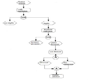
dure EPC diagram is shown.
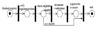
Figure3: Petri net for student admission procedure
IJSER © 2013 http://www.ijser.org
Figure4: EPC Diagram for admission procedure
International Journal of Scientific & Engineering Research, Volume 4, Issue 7, July-2013 957
ISSN 2229-5518
3.4. Unified Modelling Language Activity Diagram (UML- AD)
UML stands for Unified modelling language became OMG standard in 2004.This was originally designed to be used in the field of software engineering. It has several version and its latest version specifies fourteen different object–oriented nota- tions that capture all attributes and behaviour of the object modelled for example class notation, sequence notation etc. But the most widely used notation in business process model- ling is activity diagram/ notation [19].
In context to business process modelling, UML-AD dia- gram suitability for business process modelling was first in- vestigated by Nick Russell, Wil M.P. van der Aalst and Arthur H.M. terHofstede [15].Thus UML introduces object-oriented terminology for business process modeling, but is not meant to be a complete business modeling language at all. UML ac- tivity diagram is both flowcharting technique and data flow diagrams from development perspective to represent the se- quence of the actions of an activity. The main construct of UML activity diagram are action node, object node and control node. Action nodes represent behavioural perspective and object nodes represent information consumed or produced.
..Important control nodes are initial nodes, final nodes, deci-
sions, forks and joins. The initial and final nodes represent the
start and end of an activity diagram. Decisions are used to
direct the control flow based on some information. Forks and
joins can be used to split and merge the control flow in order to represent parallel processes [4].
Swimlane partitions and sub-activities are the two im- portant features of UML Activity Diagrams, in which swim- lane partitions can be used to group actions on some common
characteristic, while Sub-activities can be used to aggregate an activity diagram into a single activity for use in other activity diagrams. Sub-activities facilitate composition and decomposi- tion in an activity diagrams [13].
Strengths
• They support signal sending and receiving at the concep- tual level.
• They support both waiting and processing states.
• They provide a seamless mechanism for decomposing an activity into sub activities. The combination of this de- composition capability with signal sending yields a pow- erful approach to handling activity interruptions. [19].
Weaknesses:
• Some of the UML AD constructs lack a precise syntax and semantics for example the rules for linking forks with joins are not fully defined, nor the concept of dynamic in- vocation and deferred events.
• They do not fully capture important kind of synchroniza- tion such as discriminator and the N-out of M join.
• UML AD cannot capture many of the natural constructs encountered in business processes such as case and the notion of interaction with the operational environment in which the process functions [19].
Example: Figure5 shows an example of UML Activity dia- gram for simple student admission procedure.
Figure5: UML Activity diagram for student procedure system
3.5. Business process modelling notation (BPMN)
BPMN was developed by business process management initia-
tive (BPMI), which released it in 2004. BPMN is aimed to pro- vide a notation that is readily understandable by all business users, from the business analysts to technical developer. BPMN hopes to bridge the gap between the business process designs and business process implementation. BPMN defined a business process diagram (BPD), which are based on flowcharting technique and are tailored for creating graphical models of business process operations.A BPD is made up of a set of graphical objects. These elements enable easy develop- ment of business process diagrams that look familiar and easy to understandable to most business analysts [16].
The four basic categories of elements:
1. Flow Objects such events, activity and gateway.
2. Connecting Objects are sequence flow, message flow, and
association.
3. Swimlanes are pool and lane.
4. Artifacts are data objects, group and annotation. Strengths:
• BPMN enable roles to be defined at various levels of granularity through pools and swimlanes.
• It model business processes in a way that is easily under- stood by the business end users and analysts.
• BPMN supports all of the business process modeling el- ements
Weakness:
• BPMN element is hard to sketch on paper.
• There is no XML interchange format for BPMN dia- grams.
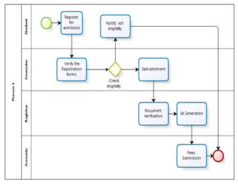
Example: In figure6 example of a BPMN diagram for student
procedure is shown which is designed with the help of BizAgi
process modeler i.e. a tool for BPMN.
IJSER © 2013 http://www.ijser.org
International Journal of Scientific & Engineering Research, Volume 4, Issue 7, July-2013 958
ISSN 2229-5518
basis of strength and weaknesses of the modeling lan- guageswhich provides quick guidelines to the business ana- lyst or practitioners. Thus Table 1 presents a summary of all the process modeling languages explained above.
Figure6: BPMN diagram for student procedure system
4. COMPARATIVE ANALYSIS
This section proposes a simple classification framework on the
5. Conclusion
Organizations adopted various business process modeling techniques time to time from different domain for instance UML which is used in object oriented domain and Petri nets for mathematical modeling etcfor better understand- ing and analysis of their business processes for which busi- ness process model are constructed with the help of busi- ness process modeling language. As they are from different domain they are not able to represent all the functionality which leads to the development of BPMN which is solely used to represent business process. This paper presents the review of five popular modeling languages with their strength and weaknesses and summarizes in tabular form which will be helpful in choosing a particular modeling language according the requirement of an organization.
Table1: Business process modelling technique
Technique | Main Constructs | Description | Strength | Weakness |
Flow chart | activity, decision, start/end and sequence | Graphic represen- tation | Communication ability, flexible, quick and simple | Lack of methodological support for different notation |
Petri nets | Places ,transition and connections | Graphical ori- ented language to de- sign, specify, simulate and verify systems | Formal mathematical rep- resentation ,well defined syntax and semantics | Time consuming while modeling |
EPC diagram | Event, function and log- ical connectors | Graphical representation | Able to represent hierarchy concept, easy, simple and support parallel execution. | Ambiguous semantics |
UML AD | Action node, object node and control node | Graphical repre- sentation of a sys- tem with different type of object | Support signal sending and receiving and decom- position of activity | Lack a precise syntax and seman- tics |
BPMN | Flow object, connecting objects ,swimlaneand artifacts | Modelling lan- guage to model business process operation | Can depict various level of granularity, and hierarchy | Hard to sketch on paper |
IJSER © 2013 http://www.ijser.org
International Journal of Scientific & Engineering Research, Volume 4, Issue 7, July-2013 959
ISSN 2229-5518
REFERENCES
[1] Anna GunhildNysetvold , John Krogstie, “Assessing Business Process Modeling Languages Using a Generic Quality Framework” , In Proceed- ings of the CAiSE'05 Workshops,2005
[2] Birgit Korherr., Business process modeling, languages, goals, and vari- abilities[PhD thesis],Vienna university of technology,9th Jan 2008 [3]Business Process Management lifecycle (Image) available from http://www.axistec.com/business-process-modeling.html
[4] Dumas M., A. Grosskopf, Hettel T., and Wynn M., “Semantics of Standard Process Models with OR-Joins,” On The Move, pp. 41-58, 2007. [5]Giaglis G., “A Taxonomy of Business Process Modeling and Infor- mation Systems Modeling Techniques”, International Journal of Flexible Manufacturing Systems, Department of Information Systems and Compu- ting, Brunel University, Uxbridge, Middlesex, UK, Vol-13, April2001.
[6] HafedhMili, Guy Tremblay, GuittaBouJaoude, Eric Lefebvre,
LamiaElabed, Ghizlane El-Boussaidi: Business process modeling lan- guages: Sorting through the alphabet soup. ACM Comput. Surv. 43(1): 4 (2010)
[7] Hammer M., and Champy, J., “Reengineering the Corporation”, Har- per Business, 1993, New York.
[8] Jensen, K. (1996) Coloured Petri Nets: Basic Concepts, Analysis Meth- ods and Practical Use, Springer Verlag, Berlin.
[9] Kettinger, W.J., Teng, J., Guha, S., 1997a. Business process change: A study of methodologies, techniques and tools. Journal of Management Information Systems 14 (1), 119–154.
[10] Kettinger, W.J., Teng, J., Guha, S., 1997b. Appendices business process change: A study of methodologies, techniques and tools. Management Information Systems Quartely Archivist 14 (1), Appendice1–8. Lakin, R.,
et al., 1996. BPR enabling
[11]Laden Aldin and Sergio de Cesare, “A comparative analysis of busi- ness process modeling techniques”, Proceedings of the U.K. Academy for Information Systems (UKAIS 2009), 14th Annual Conference, 2009.Paper
2.
[12] Leymann, F. and Altenhuber, W. (1994) Managing Business Processes as an Information Resource, IBM Systems Journal, 33, 2, pp. 326-348.
[13] Martin Devillers. Business Process Modeling as a means to bridge the
Business-IT Divide[master thesis], Radboud University Nijmegen, Version
1.3 Aug 2011.
[14] Marsan, M.A., Balbo, G., Conte, G., Donatelli, S. and Franceschinis, G. (1995) Modelling with Generalised Stochastic Petri Nets, Wiley, Chiches- ter.
[15] NickRussell,Wil M.P. van der Aalst, Arthur H.M. terHofstede, PetiaWohed, “On the Suitability of UML 2.0 Activity Diagrams for Busi- ness Process Modelling”,Third Asia-Pacific Conference on Conceptual Modelling (APCCM2006), Hobart, Australia. Conferences in Research and Practice in Information Technology, Vol. 53.
[16] Object Management Group, Business Process Model and Notation
(BPMN) Version 2.0, Object Management Group, Jan 2011.
[17] Phalp, K.. “Quantitative analysis of static models of processes”, Jour-
nal of Systems and Software 52 (2), 105–112., 1999
[18] Ruth Sara Aguilar-Savén, “Business process modelling: Review and framework”, International Journal of Production Economics, Volume 90, Issue 2, 28 July 2004, Pages 129-149
[19] Ryan K L KO, Stephen S G Lee, EngWah Lee, “Business process man- agement (BPM): A Survey”, business process management journal vol- ume15 no-5, 2009 Emerald group.
[20] Schriber, T.J. (1969) Fundamentals of Flowcharting, Wiley, New York.
[21]Wetzstein B, Ma Z, “Semantic Business Process Management: A
Lifecycle Based Requirements Analysis”, In Proceedings of the Workshop SBPM2007, Institute of Architecture of Application Systems university of Stuttgart, Germany, April 2007.
IJSER © 2013 http://www.ijser.org