International Journal of Scientific & Engineering Research Volume 4, Issue 2, February-2013 1
ISSN 2229-5518
Inertial Measurement and Filtering of a UAV flight
Abhilash Iyer, Surya Prakash Sharma
Abstract— Unmanned aerial vehicles with high agility and high performance through vertical take-off and landing (VTOL) and multirotor system have been the goal within reach of the mankind since the invention of the motion sensors. This paper details the use of an inertial measurement system consisting of a gyroscope and an accelerometer which was used on a quadrotor we built from scratch and called
'Quadbober'. The approach is based on the formulation of a DCM matrix algorithm and classical PID control system at the feedback to attain a stable flight with remote assistance. Various simulations and bench tests were performed for the calibration of the sensors and actuating devices.
Index Terms—DCM matrix algorithm, Kalman Filter, PID Controller, remote control flight, Quadrotor, Inertial Measurement Unit, Accelerometer, Gyroscope.
—————————— ——————————
uadrotors are flying machines with four rotors, which are typically fixed at a particular position. Due to their ability to be maneuvered in complex manners and be
very small in size, they are emerging as alternatives to helicop- ters for various tasks. We looked at complex projects being made at home by enthusiastic individuals and found the Aeroquad[1] project. Referring to it we performed various tests using DCM matrices and PID filters instead of the com- plex Kalman filter, testing it on a test bed that we called the Quadbober, with results showing that these multi rotor sys- tems show higher agility over the traditional twin rotor con- figurations by altering the thrusts among the four blades.
With abilities like Vertical takeoff and landing (VTOL) and the ability to land on inclined surfaces, UAV's like our Quadbober (in Figure 1) are showing great importance in the modern emergency environment where quick action is required. The ability to lift larger payloads adds to the multipurpose nature of the aircraft.
The quadrotor software runs on an AVR microcontroller that receives input from a flight pilot and then after mixing this input with the data from the sensors, controls the four rotors which affect flight. The entire craft is designed using cheap aluminum tubes.
We used an Atmega 328 microcontroller on the motherboard. The hardware consists of 14 digital input/output pins (of which 6 can be used as PWM outputs), 6 analog inputs, a 16
MHz crystal oscillator. Commercial Electronic Speed Control- lers were used to drive the high power motors required to produce the thrust required in flight, which could reach upto
————————————————
Surya Prakash Sharma is currently pursuing masters degree program in Elec-
trical & Computer Engineering in Clemson University, USA, PH-
08646435685. E-mail: s@iamsurya.com
28A for each motor to give a total of 112A.
To provide this high capacity current a battery of 4200maH
was used which could discharge at 25C under normal use and
35C for short bursts, thus giving a discharge rate of 105 A to
147 A.
The inertia measurement was done using a 9 Degree of Freedom PCB stick produced by Sparkfun, which houses 3 sensors, a gyroscope, an accelerometer and a magnetometer.
We used an InvenSense's ITG3200 triple axis, digital output gyroscope. The ITG-3200 features 16bit ADCs for digitizing the gyro outputs and supports the fast mode I2C (400 KHz) interface. It has an embedded internal temperature sensor and can be powered anywhere between 2.1 to 3.6V. The gyroscope is connected to the microcontroller through a level convertor (5V to 3.3V). Gyroscopes give out the data in terms of de- grees/ sec, which is basically the rate of change of angular orientation. Thus, on integrating these outputs with time we can find out the attitude of the Quadrotor. We have to do some coding to extract meaningful values from the gyros and are as follows.![]()
gyroRate gyroADC gyroZero
Sensitivity
Where gyroADC is the read value from the sensor, gyroZero is the value from the sensor while calibrating on a plane surface, while sensitivity for the ITG3200 is 14.375 LSB (degree/s). Thus the final result will be in degree per sec and to obtain the attitude we will have to know the exact time since the last loop. The gyro angle can be given as,
gyroAngle gyroAngle dtime
1000
IJSER © 2013 http://www.ijser.org
International Journal of Scientific & Engineering Research Volume 4, Issue 2, February-2013 2
ISSN 2229-5518
We used BOSCH's BMA180, triple axis high performance digi- tal accelerometer. It provides a digital 14 bit output signal via a 4 wire SPI or I2C interface. Accelerometers are generally used to measure the pitch and roll of the machine and give the output in terms of gravity. Pitch of an aircraft can be easily calculated by an accelerometer by the formula
Before describing the DCM matrix we need to understand that the orientation of the Quadrotor and the orientation of the earth are different at different instants and there has to be an element which transfers any force vector from one reference to other. This element is a Rotation matrix which is defined as the Direct Cosine Matrix, describing the orientation of one co- ordinate system with respect to other.
Pitch a sin
AccCal
![]()
AccFlight
Where AccCal is accelerometer value during calibration and
AccFlight is the accelerometer value during flight.
Qx
Q Qy a vector,such as a direction, velocity or acceleration
Qz
QP= a vector Q measured in the frame of reference of the plane
QG= a vector Q measured in the frame of reference of the ground
rxx
R= ryx
rxy
ryy
rxz
ryz rotation matrix
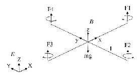
The Four rotors have fixed pitch blades attached to the shaft of the motor. Four rotors are arranged in a configuration as
rzx
QG= RQP
rzy
rzz
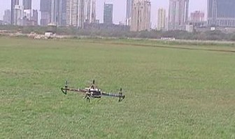
Figure 1. The DCM algorithm being tested on a commercial frame. This flight showed that sensor orientation can change in flight and still provide very good
The R matrix is generally Anti- symmetric in nature and the transpose and inverse of the R matrix is same. Thus the Quad- rotor can be in any orientation around its centre of gravity and its orientation with respect to earth can be described by speci- fying a rotation about an axis. Thus the rotation groups, which are the set of rotation matrices, will make us able to perform control and navigation of the Quadrotor in any orientation.
The Gyroscope sensors catch the orientation information and then we integrate the nonlinear differential kinematic equation which relates the time rate of change in the orientation of the Quadrotor to its rotation rate and its present orientation. This orientation information is present in the Rotation matrix.
control.
1 d
d
R t dt R t d
1 d
shown in Fig. 2 where two are counter clockwise rotating and
two are clockwise rotating to avoid the torque and to maintain a constant heading direction and yaw stabilization is achieved.
d x xdt d y ydt
d z zdt
d d
1
The above operations detail the process of updating the Direc- tion Cosine Matrix from the gyroscope signals.
Figure 2. Freebody diagram for the aircraft
Recognizing the numerical errors in the integration which will gradually violate the orthogonality constraints that DCM must satisfy. This is done by renormalization process.
IJSER © 2013 http://www.ijser.org
International Journal of Scientific & Engineering Research Volume 4, Issue 2, February-2013 3
ISSN 2229-5518
rxx ryx
X= rxy
Y= ryy
/*working variables*/
rxz
ryz
ryx
unsigned long lastTime;
double Input, Output, Setpoint;
error X Y=XT Y= rxx
rxx
rxy
rxz ryy
ryz
double errSum, lastErr;
double kp, ki, kd;
void Compute()
![]()
rxy Xorthogonal =X- error Y
2
rxz
ryx
![]()
ryy Yorthogonal =Y- error X
2
ryz
rxx
rxy Zorthogonal =Xorthogonal Yorthogonal
rxz
Numerical errors, gyro drift, and gyro offset will gradually accumulate errors in DCM elements. Use PI negative feedback controller between the detected errors and gyro inputs.
The basic objective of PID is to check whether the Quad has reached the desired point each and every second. This could be achieved by checking the inputs from the gyros (i.e posi- tions, gyro x, gyro y, gyro z) with the desired output. But the problem with this is the input of the gyro goes on changing with the movements of quad and also the time interval be- tween the two calculated positions must be kept in track.
For this arduino provides with a library function millis() , which returns the number of milliseconds since the Arduino board began running the current program. This number will overflow (go back to zero), after approximately 50 days.
Kp is the proportionality gain which is multiplied with the present error, Ki is the integral gain which is multiplied with integral of error in the time span of previous PID iteration and the present iteration, Kd is the derivative gain which is multi- plied with the rate of change of error in the time span between two PID iterations.
{ /*How long since we last calculated*/
unsigned long now = millis();
double timeChange = (double)(now - lastTime);
/*Compute all the working error variables*/
double error = Setpoint - Input;
errSum += (error * timeChange);
double dErr = (error - lastErr)/ timeChange;
/*Compute PID Output*/
Output = kp * error + ki * errSum + kd * dErr;
/*Remember some variables for next time*/
lastErr = error;
lastTime = now;
}
void SetTunings(double Kp, double Ki, double Kd)
{
kp = Kp; ki = Ki; kd = Kd;
}
IJSER © 2013 http://www.ijser.org
International Journal of Scientific & Engineering Research Volume 4, Issue 2, February-2013 4
ISSN 2229-5518
Since the DCM and PID algorithmic combination is essentially an alternative for the complex Kalman filter algorithm, we see it being used wherever Inertial Measurement units exist, which includes aircraft, robots, vehicles and mobile phones. The quadrotor aircraft is an exponential improvement over the helicopter, at least when it is not being manned.
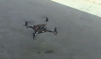
We foresee applications in the military, and also humanitarian where the quadrotor can provide aerial support during emer- gencies, for example during floods or fires, the quadrotor when outfitted with a camera can provide rapid recconisance of a particular region. When provided the correct motors, it can even be used to carry variable payloads. Our second im- plementation shown in Figure. 3 allowed payloads of upto
140g to be carried. Future improvements include those envi- sioned and worked upon by Dr. Kumar [2] where multiple robots can be a part of a swarm.
We initially started out with various mechanical designs as- suming it to be the easiest part of the entire project, but we soon realized that mechanical inefficiencies cause much more issues that one can foresee. It was not as easy to create a frame for the craft as we had originally assumed, because drilling manually does not provide the accuracy needed when align- ing various parts together. Various materials were tried, (in- cluding Carbon fiber, which is known to be strong) only to realize that the strength of the material is dependent on the application, and cannot be assumed to be a global statistic. The biggest issue was the vibrations caused by the motors, which would completely overwhelm the data from the accelerome- ter, which essentially reports the force acting on the device. The noise would cause instantaneous changes in the data be- ing read by the accelerometer causing the DCM and PID com- bination algorithm to fail completely. It is probable that the Kalman filter would perform much better in this scenario, however it is something we are still to look at.
Figure 3. Second version of the Quadbober lifting a sqaure wooden block of
140g as payload. There was no change in the control efficiency of the craft.
Thanks to our Professors for their guidance. . Huge thanks to our Head Of Department, Electronics and Telecommunication, Mrs Savita Bhosale for her continued support and guidance and Mrs. Shashi Prabha, Head of Department, Electrical Engi- neering for her guidance in the design of the project .
[1] Ted Carancho, Aeroquad, Internet: www.aeroquad.com
[2] Subhrajit Bhattacharya , Hordur Heidarsson , Gaurav S. Sukhatme and Vijay Kumar. "Cooperative Control of Autonomous Surface Vehicles for Oil Skimming and Cleanup" in Proc. IEEE ICRA May 2011.
[3] Robert Mahony, Sung-Han Cha, Tarek Hamel. "A coupled estimation and control analysis for attitude stabilisation of mini aerial vehicles." ACRA, Auckland, Dec. 2006
IJSER © 2013 http://www.ijser.org