Improvement of Direct torque control
Performance by using Discrete SVM Techniques
Abhilasha Parthan, Prince Asok A
Abstract— Direct torque is a control technique used in a AC drive systems to obtain high performance torque control.The low number of voltage vectors which can be applied to the machine using the basic DTC scheme may cause undesired torque and current ripple.In order to reduce the torque,flux, current and speed ripple a Discrete Space Vector Modulation(DSVM-DTC) implemented.DSVM-DTC,use a kind of space vector modulation to produce more voltage vectors than are available with the classical DTC.The performance of this control methods has been demonstrated by simulation with MATLAB/SIMULINK..
Index Terms— Direct torque control, Discrete space vector modulation,induction motor,torque and current ripple,voltge vectors.
—————————— ——————————
1 INTRODUCTION
Alternating current motors are getting more and more popular for applications in industrial environments. Particu- larly in speed control systems, ac induction motors are more widely used nowadays due to the characteristics of higher efficiency, less inertia, smaller volume and lower cost. The capabilities to operate at higher speeds, higher torques and larger power ratings make the induction motors more attrac- tive than dc motors for medium and high power motor drives.
In recent years, research interest in IM sensorless drives has grown significantly due to some of their advantages, such as mechanical robustness, simple construction and mainte- nance [6]. Present efforts are devoted to improve the sensor- less operation, especially for low speed and to develop robust control strategies.
The DTC is one of the actively researched control schemes which are based on the decoupled control of stator flux and torque providing a quick and robust response with high and low speed present notable torque, flux, current and speed rip- ple.
In this paper a new control technique, DSVM-DTC is introduced which allows the performance of DTC scheme in terms of flux and torque ripple and current dis- tortion to be improved. These results can be achieved without increasing the complexity of the power circuit and the inverter switching frequency.
Sections II and III presents the proposed direct torque control strategy and direct torque control of induc- tion motor based on discrete space vector modulation strategy. Section IV gives the simulation results of the pro- posed methods. Finally, conclusions are given in section V.
Section IV gives the simulation results of the pro- posed methods. Finally, conclusions are given in section V.
DIRECT TORQUE CONTROL STRATEGY
Direct torque control (DTC) has become an alternative to the well known Vector Control of induction machine. It was introduced in Japan by Takahashi (1984) and also in Germany by Depenbrock (1985). DTC of induction machine has increasingly become the best alternative to field orien- tation methods or vector control. The Direct Torque Con- trol (DTC) method is characterised by its simple implemen- tation and a fast dynamic response. The main advantages of DTC are absence of coordinate transformation and cur- rent regulator absence of separate voltage modulation block [1].
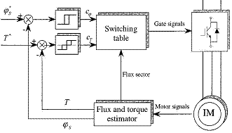
A block diagram of a DTC system for an induction ma- chine is shown in Figure. 1[2]. DTC scheme uses a station- ary d-q reference frame. Torque and flux are controlled by the stator voltage space vector defined in this reference frame.
Figure. 1: Direct torque control of induction machine
IJSER © 2013
http://www.ijser.org
In principle the DTC selects one of the six voltage vec- tors and two zero voltage vectors generated by a VSI in order to keep stator flux and torque within the limits of two hysteresis bands. The presence of hysteresis controllers leads to a variable switching frequency operation. In addi- tion, the basic DTC scheme may cause undesired torque and current ripple. The use of a switching table for voltage vector selection provides fast torque response, low inverter switching frequency and low harmonic losses. The DTC controller consists of two hysteresis comparator (flux and torque) to select the switching voltage vector in order to maintain flux and torque between upper and lower limit.
A. DTC development
The develop torque control of inverter fed induction machine is carried out by hysteresis control of magnitude stator flux and torque that selects one of the six non-zero and two zero inverter voltage vectors shown in Fig. 2. The selection is made in order to maintain torque and flux error inside the hysteresis band in which the errors are indicated by ∆Te and ∆ψs respectively. Noting that
∆Te = Teref − Te (1)
∆ψs = ψsref − ψs (2)
The operation may be described by the following manner: Sa=1 means top switch closed, bottom switch opened. Sa=0 means top switch opened, bottom switch closed
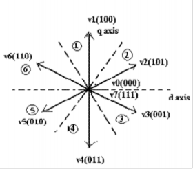
Figure. 2: Inverter output voltage vectors
The electromagnetic torque value resulting from the previous stage is then compared with the electromagnetic torque reference, using the three level hysteresis comparator, represented in figure 3. In this manner, the result may be increase, decrease or maintain the torque, depending on the comparator output [3].
Figure 3. Three level hysteresis comparator: τ =1⇒ increase torque; τ
=0⇒ maintain torque; τ = -1⇒ decrease torque.
C. Stator flux control
In a similar way, the flux value will be compared with a flux reference, but using a two level hysteresis comparator, shown in figure 4. The result will be used to increase or decrease the flux [3].
Switching vector selection
It is necessary to know the angular sector in which the ac- tual flux is located. The actual position can be determined by Equation (3), from the orthogonal flux components:
θfs =tanˉ(Φqs / Φds ) (3)
The θ angle returned by Equation (3) determines the sector
where the flux is, (figure 2).
Τ |
θ |
1 |
2 |
3 |
4 |
5 |
6 |
-1 |
0 |
V5 |
V4 |
V3 |
V2 |
V1 |
V6 |
0 |
0 |
V0 |
V7 |
V0 |
V7 |
V0 |
V7 |
1 |
0 |
V3 |
V2 |
V1 |
V6 |
V5 |
V4 |
TABLE.1 SWITCHING TABLE FOR CONVENTIONAL DTC
-1 |
1 |
V6 |
V5 |
V4 |
V3 |
V2 |
V1 |
0 |
1 |
V7 |
V0 |
V7 |
V0 |
V7 |
V0 |
1 |
1 |
V2 |
V1 |
V6 |
V5 |
V4 |
V3 |
Sector calculation-
0 ≤ θfs ≤ 60 (sector 2)
-60 ≤ θfs ≤ 0 (sector 3)
-120 ≤ θfs ≤ -60 (sector 4)
-180 ≤ θfs ≤ -120 (sector 5)
120 ≤ θfs ≤ 180 (sector 6)
60 ≤ θfs ≤ 120 (sector 1)
The combination of the comparators outputs and the sector is then applied to an optimal switching table (Table 1) which will give the voltage vector to be applied to the in- verter.
DIRECT TORQUE CONTROL OF INDUCTION MOTOR BASED ON SPACE VECTOR MODULATION
STRATEGY
The main idea the DSVM-DTC control strategy is to force the torque and stator flux to approach their reference by applying in one sampling period several voltage vectors instead of only one voltage vector as in basic DTC.[7]
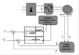
Figure 5: DSVM-DTC control scheme.
This control algorithm uses prefixed time intervals within a cycle period and in this way a higher number of voltage space vectors can be synthesized with respect to those used in basic DTC technique The increased number of voltage vectors allows the definition of switching tables according to the rotor speed the flux and torque errors. With DSVM- DTC strategy, 19 voltage vectors can be selected for each sector, according to the rotor speed, the flux and the torque errors range as is represented in Figure.6 and TABLE 2. The switching period is divided into three equal time intervals and one voltage vector is applied at each time interval.
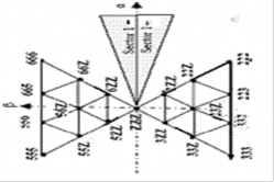
Figure.6 voltage vector obtained by using DSVM with three equal time interval
An asymmetry in torque behaviour because of s induced voltage. The DSVM calculates this voltage and it to choose an appropriate voltage vector. The opera range from zero speed up to where induced voltage eq the applied voltage vectors is divided into three reg Low, Medium and High. Given by Figure.7 [1].
Speed voltage
peed use ting uals ion;
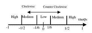
Figure 7: Speed voltage regions.
The voltage induced is


ωr= Φsd
-Φsq
But only its value is used, so calculated voltage is
Vs = ωrΦs
This is then compared to the regions.
Sector calculation
The DSVM use twelve sectors instead of six; all of the six sectors in DTC are divided in half. The finer division of sectors is used in the high-speed region. At medium and low speed range only six sectors are used, Show figure .8
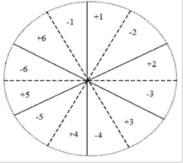
Figure.8 DSVM sectors
Torque hysteresis
The DSVM can produce more voltage vectors which if properly applied produce less ripple. To achieve this, the torque hysteresis has 5 levels instead of two. Figure8. If torque error is small hysteresis is in state 0. In this case a voltage vector is chosen trying to maintain torque at its ac- tual level. If hysteresis is in state +/– 1, a vector just as big as to push torque into the small region is chosen. When hysteresis is in state +/– 2, a vector compensating for the error as fast as possible is chosen, i.e. the same vectors used in the classical DTC [1].
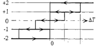
Figure .9: 5-level hysteresis comparator
TABLE 2: LOOK UP TABLES
1-low speed voltage
Τ | θ | 1 | 2 | 3 | 4 | 5 | 6 |
-2 | 0 | 555 | 444 | 333 | 222 | 111 | 666 |
-1 | 0 | 5ZZ | 4ZZ | 3ZZ | 2ZZ | 1ZZ | 6ZZ |
0 | 0 | ZZZ | ZZZ | ZZZ | ZZZ | ZZZ | ZZZ |
1 | 0 | 3ZZ | 2ZZ | 1ZZ | 6ZZ | 5ZZ | 4ZZ |
2 | 0 | 333 | 222 | 111 | 666 | 555 | 444 |
-2 | 1 | 666 | 555 | 444 | 333 | 222 | 111 |
-1 | 1 | 6ZZ | 5ZZ | 4ZZ | 3ZZ | 2ZZ | 1ZZ |
0 | 1 | ZZZ | ZZZ | ZZZ | ZZZ | ZZZ | ZZZ |
1 | 1 | 2ZZ | 1ZZ | 6ZZ | 5ZZ | 4ZZ | 3ZZ |
2 | 1 | 222 | 111 | 666 | 555 | 444 | 333 |
2–medium speed voltage
Τ | θ | 1 | 2 | 3 | 4 | 5 | 6 |
-2 | 0 | 555 | ω444 | 333 | 222 | 111 | 666 |
-1 | 0 | ZZZ | ZZZ | ZZZ | ZZZ | ZZZ | ZZZ |
0 | 0 | 3ZZ | 2ZZ | 1ZZ | 6ZZ | 5ZZ | 4ZZ |
1 | 0 | 33Z | 22Z | 11Z | 66Z | 55Z | 44Z |
2 | 0 | 333 | 222 | 111 | 666 | 555 | 444 |
-2 | 1 | 666 | 555 | 444 | 333 | 222 | 111 |
-1 | 1 | ZZZ | ZZZ | ZZZ | ZZZ | ZZZ | ZZZ |
0 | 1 | 2ZZ | 1ZZ | 6ZZ | 5ZZ | 4ZZ | 3ZZ |
1 | 1 | 22Z | 11Z | 66Z | 55Z | 44Z | 33Z |
2 | 1 | 222 | 111 | 666 | 555 | 444 | 333 |
3–high speed voltage (+1 sector)
Τ | θ | 1 | 2 | 3 | 4 | 5 | 6 |
-2 | 0 | 555 | 444 | 333 | 222 | 111 | 666 |
-1 | 0 | 3ZZ | 2ZZ | 1ZZ | 6ZZ | 5ZZ | 4ZZ |
0 | 0 | 33Z | 22Z | 11Z | 66Z | 55Z | 44Z |
1 | 0 | 333 | 222 | 111 | 666 | 555 | 444 |
2 | 0 | 333 | 222 | 111 | 666 | 555 | 444 |
-2 | 1 | 666 | 555 | 444 | 333 | 222 | 111 |
-1 | 1 | 2ZZ | 1ZZ | 6ZZ | 5ZZ | 4ZZ | 3ZZ |
0 | 1 | 23Z | 12Z | 61Z | 56Z | 45Z | 34Z |
1 | 1 | 223 | 112 | 661 | 556 | 445 | 334 |
2 | 1 | 222 | 111 | 666 | 555 | 444 | 333 |
Τ | θ | 1 | 2 | 3 | 4 | 5 | 6 |
-2 | 0 | 555 | 444 | 333 | 222 | 111 | 666 |
-1 | 0 | 3ZZ | 2ZZ | 1ZZ | 6ZZ | 5ZZ | 4ZZ |
0 | 0 | 23Z | 12Z | 61Z | 56Z | 45Z | 34Z |
1 | 0 | 33Z | 22Z | 11Z | 66Z | 55Z | 44Z |
2 | 0 | 333 | 222 | 111 | 666 | 555 | 444 |
-2 | 1 | 666 | 555 | 444 | 333 | 222 | 111 |
-1 | 1 | 2ZZ | 12Z | 6ZZ | 5ZZ | 4ZZ | 3ZZ |
0 | 1 | 22Z | 11Z | 66Z | 55Z | 44Z | 33Z |
1 | 1 | 222 | 111 | 666 | 555 | 444 | 333 |
2 | 1 | 222 | 111 | 666 | 555 | 444 | 333 |
4–high speed voltage (-1sector)
D .Look-up table
The look-up table in this case has four input variables; flux and torque hysteresis state, sector number and speed voltage. Since the system chose voltage vectors depending on the emf, each speed region uses different switch tables (Table2). When the system operates in the high speed re- gion two switch tables for each sector are used. Because the emf introduces an asymmetry, the switch tables also be- come asymmetric. Hence, different tables must be used for positive and negative rotational directions For example; the label "23Z" denotes the voltage vector which is synthesized by using the voltage space vectors V2, V3 and V0 or V7, each one applied for one third of the cycle period.
IV.SIMULATION RESULTS
The performance of this control methods have been demonstrated by simulations with MATLAB/SIMULINK (matlab7.1) package. The results of simulation of DTC and DSVM_DTC of induction motor are shown in Figure 10, 11,12 and 13 respectively.
The simulation results show that flux and torque re- sponses are very rapid for two DTC methods. By DSVM_DTC technique shown in figure 11b, the ripple of torque in steady state is reduced remarkably compared with DTC, the torque changes through big oscillation and the torque ripple is bigger in DTC shown Figure 11a. How- ever, the large torque ripple in steady-state operation is one of its major drawbacks.
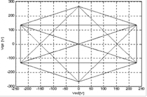
The improved DTC system, DSVM, can produce more voltage space vectors than the basic DTC Figure 10a and 10b.The larger number of space vectors are used to de- crease torque ripple in steady-state operation.
We can observe an optimal reduction of the flux oscillations, as shown in Figure.12b, that the stator flux tra- jectory of the DSVM_DTC is more approximately circle than it of the conventional DTC shown in Figure 12.a, con- sequently, as illustrated in Figure.13b, the current have less harmonic distortion that compared with DTC shown in Fig- ure13a.
Figure10.a stator voltage in DTC
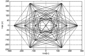
Figure10.b stator voltage in DSVM-DTC
Figure.11 a. Torque response in DTC
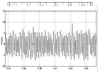
Figure.11 a. Torque response in DTC
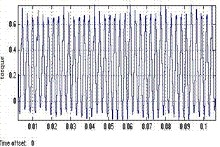
Figure.11b .torque response in DSVM-DTC
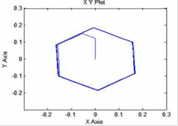
Figure13.b the stator current (Iabc) DSVM-DTC
V.CONCLUSION
Figure12.a the stator flux circle DTC
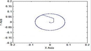
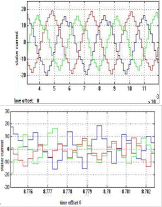
Figure12.b the stator flux circle DSVM-DTC
Figure13a the
Figure13a the stator current (I abc) DTC
Direct Torque Control of induction motor is one of the modern techniques used for speed and torque control of induction motor. The low number of voltage vectors which can be applied to the machine using the basic DTC scheme may cause undesired torque and current ripple. This drawback is avoided by using DSVM-DTC.Both DTC and DSVM-DTC are simulated using simulink.The large num- ber of voltage vectors used in DSVM-DTC would improve performance in terms low ripple, but they would require large and complex look-up table.
APPENDIX
The parameters of induction motor are as follows:
Power rating : 3hp
Rated voltage : 220V
Pole pair 2
Stator resistance : 0.435ohm
Stator inductance : 0.0022H
Rotor resistance : 0.861ohm
Rotor inductance : 0.002H Magnetizing inductance : 0.06931H Inertia : 0.089
Reference speed : 1750rpm
REFERENCES
[1] R. Toufouti, S. Meziane and H. Benalla, “Direct torque control for induction motors based on discrete space vector modulation”, In- ternational Journal of Applied Engineering Research ,Volume 2, Number 3 (2007), pp. 453–466.
[2]. H.F. Abdul Wahab and H. Sanusi,”Simulink model of direct torque control of induction machine”, American Journal of Applied Sciences 5 (8): 1083-1090, 2008.
[3] Nuno M. Silva, António P. Martins, Adriano S. Carvalho ,Torque and speed modes simulation of a dtc-controlled induction motor”, Pro- ceedings of the 10th Mediterranean Conference on Control and Auto- mation - Lisbon,Portugal,July9-12,2002.
[4] Casadei, D. and Serra. G, “Implementation of direct Torque control Algorithm for Induction Motors Based on Discrete Space Vector Modulation”, IEEE Trans. Power Electronics., Vol.15, N°.4, JULY (2002)
[5] F. Khoucha, K. Marouani, A. Kheloui, K. Aliouane, “A DSP-based discrete space vector modulation direct torque control of sensorless induction machines”, UER Electro technique,) ,BP 17 Bordj-El-Bahri, Algiers, Algeria..
[6] Thomas G. Habetler and Deepakraj M. Divan, “Control Strategies for Direct Torque Control Using Discrete Pulse Modulation”, IEEE Transactions On Industry Applications, Vol. 21, No. 5, September Oc- tober 1991 893.