International Journal of Scientific & Engineering Research Volume 2, Issue 5, May-2011 1
ISSN 2229-5518
Implementation of RSA Cryptosystem
Using Verilog
Chiranth E, Chakravarthy H.V.A, Nagamohanareddy P, Umesh T.H, Chethan Kumar M.
Abstract-The RSA system is widely employed and achieves good performance and high security. In this paper, we use Verilog to implement a 16-bit RSA block cipher system. The whole implementation includes three parts: key generation, encryption and decryption process. The key generation stage aims to generate a pair of public key and private key, and then the private key will be distributed to receiver according to certain key distribution schemes. Data security is achieved after the 64-bit input data are block encrypted by RSA public key. The cipher text can be decrypted at receiver side by RSA secret key. These are simulated in NC LAUNCH and hardware is synthesized using RTL Compiler of CADENCE. Netlist generated from RTL Compiler will be used to generate IC.
Index Terms - Cadence, Cryptosystem, Decryption, Encryption, Implementation, Key Generation, Modular Exponentiation, Modular
Multiplication, RSA, Verilog.
—————————— • ——————————
1 INTRODUCTION
HE first public key scheme was developed in
1977 by Ron Rivest, Adi Shamir, and Len Adleman at MIT. Now Rivest-Shamir-Adleman (RSA) is the most widely accepted and implemented public key cryptosystem. The public key system is based on using different keys, one key for encryption and a different but related key for decryption. The whole process involves computing the remainder after exponential and modular operation of large number. Encryption and decryption have the following form, for some plaintext block M and cipher text block C:
C = M e mod n. M = C d mod n.
Generally, it includes a third party to generate a pair of public key and to distribute keys to transmitter and receiver. Transmitter and receiver should both know the value of n. The transmitter has the knowledge of public key e, and only the receiver knows the private key d. Thus, a public key of (e, n) and secret key (d, n) generated by third party is distributed to transmitter and receiver separately. For this algorithm to be satisfactory for public-key encryption, the following requirements must be met:
1. It is possible to find values of e, d, n that
M^d*e mod n = M1 for all M < n.
2. It is relatively easy to calculate M^e mod n and Cd for all values of M < n.
3. It is infeasible to determine d given e and n.
Steps involved in Implementation of RSA:
The following step is taken to implement the RSA
public key scheme:
1. Choose two large prime numbers, p and q. Let n=p*q, Let <P(n) = (p-1)*(q-1).
2. Randomly choose a value e (1< e < <P(n)), which is relative prime to <P(n) that gcd (e, <P(n)).
3. Calculate d=e-1 mod <P(n), send public key (e, n)
to transmitter and secret key (d, n) to receiver.
4. Transmitter encrypt the original message, C = M
e mod n, then send cipher text to receiver.
5. Receiver decrypt cipher text by
M = C d mod n and retrieve the original message.
The rest of the paper is organized as follows: Section 2 gives an overview of RSA Implementation. Section 3 gives the simulation results. Section 4 gives the conclusion. The final section gives the references used.
2 RSA Implementation
The RSA algorithm was inverted by Rivest, Shamir, and Adleman in 1977 and published in
1978. It is one of the simplest and most widely used public-key cryptosystems. Fig.1 summarizes the RSA algorithm.
IJSER © 2011 http://www.ijser.org
International Journal of Scientific & Engineering Research Volume 2, Issue 5, May-2011 2
ISSN 2229-5518
such that gcd(<(n), e) = 1, and private exponent d is obtained by inverting e modulo <(n). E and d are also stored in registers.
Once n, d, and e are generated, RSA
encryption/decryption is simply a modular
exponentiation operation. Fig.3 shows the RSA encryption/decryption structure in hardware implementation.
Fig.1 The RSA algorithm 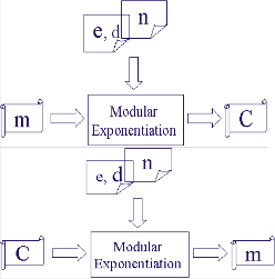
Fig.3 The RSA encryption/decryption structure
Fig.2 The system architecture for RSA key generation
The system architecture for key generation is shown in Fig.2. A random number generator generates 16-bit pseudo random numbers and stores them in the rand FIFO. Once the FIFO is full, the random number generator stops working until a random number is pulled out by the primality tester. The primality tester takes a random number as input and tests if it is a prime. Confirmed primes are put in the prime FIFO. Similarly to the random number generator, primality tester starts new test only when prime FIFO is not full. A lot of power is saved by using the two FIFOs because computation is performed only when needed. When new key pair is required, the down stream component pulls out two primes from the prime FIFO, and calculates n and <(n). N is stored in a register. <(n) is sent to the Greatest Common Divider (GCD), where public exponent e is selected
The core of the RSA implementation is how efficient the modular arithmetic operations are, which include modular addition, modular subtraction, modular multiplication and modular exponentiation. The RSA also involves some regular arithmetic operations, such as regular addition, subtraction and multiplication used to calculate n and <(n), and regular division used in GCD operation
2.1 Random Number Generator
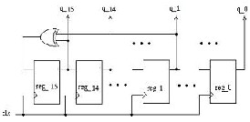
Linear Feedback Shift Register (LFSR) is used to generate random numbers. In theory, an n-bit linear feedback shift register can generate a (2n -
1)-bit long random sequence before repeating.
However, an LFSR with a maximal period must
satisfy the following property: the polynomial
formed from a tap sequence plus the constant 1 must be a primitive polynomial modulo 2. We are unable to find the primitive polynomial for a 16-bit LFSR, so we implemented a 16-bit LFSR and used its least significant 16 bits to generate 16-bit random numbers. Fig.4 shows the structure of the
16-bit LFSR.
IJSER © 2011 http://www.ijser.org
International Journal of Scientific & Engineering Research Volume 2, Issue 5, May-2011 3
ISSN 2229-5518
Modular Multiplication: Input: A, B, n
Output: M = A*B mod n
Fig.4 Structure of the 16-bit LFSR
2.2 GCD
After we get <(n), we need to find a small number e with gcd(<(n),e) = 1, which indicates that e is relative prime to <(n).
Extended Euclidean algorithm was implemented
to find gcd(<(n),e), if the gcd is 1, e and its multiplicative inverse d are returned. The following pseudo code shows Euclidean algorithm and extended Euclidean algorithm.
Euclid(a,b) A<=a; B<=b; loop if B=0
Return A=gcd(a,b);
end if R=AmodB; A<=B; B<=R;
goto loop;
Extended Euclid (m,b)
(A1, A2, A3) <= (1, 0, m); (B1, B2, B3) <= (0, 1, b);
loop: if B3 = 0
return A3 = gcd(m,b);
end if
if B3 = 1
return B3 = gcd(m,b);B2 = b-1 mod m;
end if
Q <= LA3/B3J;
(T1, T2, T3) <= (A1 - Q*B1, A2 - Q*B2, A3 - Q*B3); (A1, A2, A3) <= (B1, B2, B3); (B1, B2, B3) <= (T1, T2, T3);
goto loop;
2.3 Encryption and Decryption
Modular Multiplication: We constructed modular multiplication using shift-add multiplication algorithm. Let A and B are two k-bit positive integers, respectively. Let Ai and Bi are the ith bit of A and B, respectively. The algorithm is stated as follows:
P <= A; M <= 0;
for i = 0 to k-1 if Bi = 1
M <= (M + P) mod n;
end if
P <= 2*P mod n;
end for
return M;
For a 16-bit modular multiplier, inputs A and B are both 16 bits. However, B might be a small number with a lot of leading 0s. In the implementation, before getting into the shift-add iterations, we search for the position of the first leading 1 in B, and set (k-1) to be this position. By doing this, we avoid unnecessary shift and modular operations, making the multiplication faster when B is small. We used Omura's method to correct the partial product M and temporary value P when any of them becomes greater than 216. The corrected M and P may still greater than n, so before returning M, we will do final correction on M to make sure M is less than n.
Modular Exponentiation: The modular exponentiation operation is simply an exponentiation operation where modular multiplication is intensively performed. We implemented the 16-bit modular exponentiation components using LR binary method, where LR stands for the left-to-right scanning direction of the exponent.
The following pseudo code describes the LR binary
algorithm.
Modular Exponentiation: Input: A, B, n
Output: E = AB mod n
E <= 1;
for i = k-1 to 0
if Bi = 1
E <= A*E mod n;
end if
if i = 0
E <= E*E mod n;
end if
IJSER © 2011 http://www.ijser.org
International Journal of Scientific & Engineering Research Volume 2, Issue 5, May-2011 4
ISSN 2229-5518
end for return E;
Similar to modular multiplication, we search for the position of the first leading 1 in exponent B and set (k - 1) to be the position. This avoids unnecessary modular squaring operations. For small exponent such as the public exponent e, the modular exponentiation is much faster than big exponent such as the private exponent d.
3 Simulation results
The Random number generator, Primality tester, GCD, Encryption and decryption are written in Verilog Code and simulated in NC Launch and synthesized in RTL Compiler and Results are mentioned below. Sections below gives the respective simulation results.
3.1 Random number generator
The 16-bit random number generator implemented in Cadence using the 16-bit LFSR is shown in Fig.5.
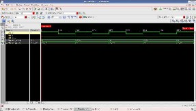
Fig.5 Simulated Waveform for Random number generator in nclaunch
Fig.5 shows the waveform of the random odd number generator which has generated few odd numbers that is 1091, 5455 and 20863.
After using the path of setup.g and slow_normal.lib and elaborating, the RTL view is generated for random number generator.
3.2 Primality tester
The 16-bit Primality tester implemented in
Cadence is shown in Fig.6.
Fig.6 Simulated Waveform for Primality tester in nclaunch
Fig.6 shows the waveform for primality tester in which 37 is given as input and it checks whether the number is prime or not, and resulted in giving
37 as prime number.
After using the path of setup.g and slow_normal.lib and elaborating, the RTL view is generated for Primality tester.
3.3 GCD
The 16-bit GCD (extended Euclidean algorithm)
implemented in Cadence is shown in Fig.7.
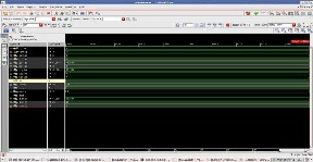
Fig.7 Simulated Waveform for GCD in nclaunch
Fig.7 shows the waveform for extended Euclidean algorithm in which two inputs are given A3=72 and B3=5, the resulted output is the public key e=5 and the private key d=29.
After using the path of setup.g and slow_normal.lib and elaborating, the RTL view is generated for GCD.
3.4 Encryption and Decryption
The 16-bit Modular Multiplication implemented in
Xilinx ISE design suit is shown in Fig.8.
IJSER © 2011 http://www.ijser.org
International Journal of Scientific & Engineering Research Volume 2, Issue 5, May-2011 5
ISSN 2229-5518
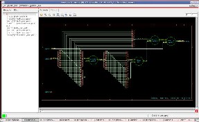
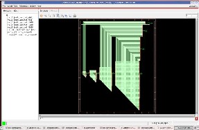
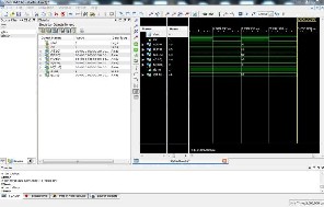 Fig.10 RTL view of encryption
Fig.8 Simulated Waveform for Modular multiplication in Xilinx
Fig.8 shows the waveform for modular multiplication module in which the input value is A=79, B=83 and N=58, the resulted output is M=3.
The 16-bit Encryption module implemented in
Cadence is shown in Fig.9,10.
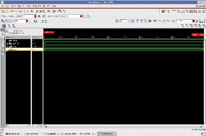
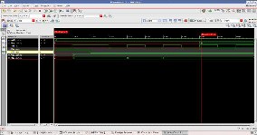
Fig.9 Simulated Waveform for encryption in nclaunch
Fig.9 shows the waveform for encryption module in which the input value is e=5, n=91 and plain text p=8, the resulted output is the encrypted cipher text m=8.
After using the path of setup.g and slow_normal.lib and elaborating, the RTL view generated for Encryption is shown in Fig.10.
The 16-bit decryption module implemented in
Cadence is shown in Fig.11,12.
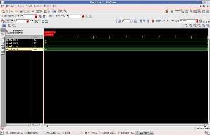
Fig.11 Simulated Waveform for decryption in nclaunch
Fig.11 shows the waveform for decryption module in which the input value is d=29, n=91 and cipher text p=8, the resulted output is the encrypted plain text m=8.
IJSER © 2011 http://www.ijser.org
International Journal of Scientific & Engineering Research Volume 2, Issue 5, May-2011 6
ISSN 2229-5518
the cipher text, after decryption we got back the plain text P=88.
4 Conclusion
Fig.12 RTL view of decryption
After using the path of setup.g and slow_normal.lib and elaborating, the RTL view generated for decryption is shown in Fig.12
3.5 Top Module (RSA)
The 16-bit Entire RSA Module implemented in
Xilinx ISE design suit is shown in Fig.13.
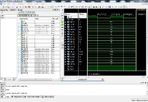
Fig.13 Simulated Waveform for Top module (RSA)
in Xilinx
Fig.13 shows the waveform of the Top module of entire RSA. Here the random prime number generated are 101 and 43 which are P and Q ie P=101 and Q=43. After getting P and Q, n and <P(n) are calculated ie n=4340 and <P(n)=4200. And public key e is selected by random prime number as e=11. GCD checks whether e and <P(n) are relatively prime or not by getting the GCD as 1, and using Extended Euclidean algorithm d is calculated as d=2291. Now the plain text M=88 is given, and by using e and n, after encryption we get the cipher text C=586. Now by using d, n and
In this, we implemented a 16-bit RSA circuit in Verilog. It is a full-featured RSA circuit including key generation, data encryption and data decryption. In our Verilog implementation of RSA, we have implemented GCD algorithm using Euclidean algorithm, random number generator using LFSR and Encryption and Decryption using Modular multiplication and modular exponentiation algorithms (L-R binary algorithms). Each sub-component and top module of RSA was simulated in Cadence/Xilinx and proved functionally correct. Netlist were generated which will be used to generate IC. The total area required for encryption and decryption is 6060nm.
We can gain more security than the other strategy because we use the random numbers. And our implementation can easily extend to large bits such as 256 or 1024 or even longer. Future work has to be carried out on Cadence and xilinx to implement in FPGA and to generate IC.
References
[1] R.L.Rivest, A.Shamir, and L. Adleman, “A Method for Obtaining Digital Signatures and Public-Key Cryptosystems”, Communications of the ACM 21 (1978)
[2] Behrouz A.Forouzan, “Cryptography and Network Security”, Tata McGraw Hill, Special Indian Edition 2007.
[3] William Stallings, “Cryptography and Network Security”, Prentice-Hall of India private limited, Third Edition 2004.
[4] Neal Koblitz, “A Course in Number Theory and
Cryptography”, Springer, Second Edition 2000.
[5] Implementing the Rivest, Shamir, Adleman cryptographic algorithm on the Motorola 56300 family of digital signal
processors. [http://ieeexplore.ieee.org/stamp/stamp.jsp?arnumber=00535035] [6] Modular Arithmetic for RSA Cryptography. [Courtesy:http://gtk.hopto.org:8089/MODULARRSA.pdf]
[7] RSA Encryption
[Courtesy:http://www.geometer.org/mathcircles/RSA.pdf]
[8] Implementing a 1024-bit RSA on FPGA. [Courtesy:http://www.arl.wustl.edu/~jl1/education/cs502/course_p roject.htm].
[9] Ridha Ghayoula, ElAmjed Hajlaoui, Talel Korkobi, Mbarek Traii, Hichem Trabelsi, “FPGA Implementation of RSA Cryptosystem”, International Journal of Engineering and Applied Sciences 2:3 2006.
[10] Tzong-Sun Wu, Han-Yu Lin,” Secure Convertible
Authenticated Encryption Scheme Based on RSA”, Informatica 33
(2009) 481-486.
[11] Guilherme Perin, Daniel GomesMesquita, and Jo˜ao
BaptistaMartins, “MontgomeryModularMultiplication on
Reconfigurable Hardware: Systolic versus Multiplexed Implementation”, Hindawi Publishing Corporation International Journal of Reconfigurable Computing Volume 2011.
IJSER © 2011 http://www.ijser.org
International Journal of Scientific & Engineering Research Volume 2, Issue 5, May-2011 7
ISSN 2229-5518
[12] Muhammad I. Ibrahimy, Mamun B.I. Reaz, Khandaker Asaduzzaman and Sazzad Hussain, “FPGA Implementation of RSA Encryption Engine with Flexible Key Size”, International Journal of Communications.
[13] Chung-Hsien Wu, Jin-Hua Hong and Cheng-Wen Wu, “VLSI
Design of RSA Cryptosystem Based on the Chinese Remainder
Theorem”, Journal of Information Science and Engineering 17,
967-980 (2001).
[14] Md. Ali-Al-Mamun, Mohammad Motaharul Islam, S.M. Mashihure Romman and A.H. Salah Uddin Ahmad, “ Performance Evaluation of Several Efficient RSA Variants”, IJCSNS International Journal of Computer Science and Network Security, VOL.8 No.7, July 2008
[15] Ramzi A. Haraty, N. El-Kassar and Bilal Shibaro, “A
Comparative Study of RSA Based Digital Signature Algorithms”,
Journal of Mathematics and Statistics 2 (1): 354-359, 2006.
[16] Yi-Shiung Yeh, Ting-Yu Huang, Han-Yu Lin and Yu-Hao
Chang, “A Study on Parallel RSA Factorization”, Journal of
Computers, vol. 4, no. 2, February 2009.
[17] D. Boneh and H. Shacham, “Fast Variants of RSA”,
CryptoBytes, Vol. 5, No. 1, pp. 1-9, 2002.
Authors

Chethan Kumar M received his B.E degree in Electronics and Communication Engineering in Bahubali College of Engineering, Shravanabelagola, India. Under VTU Belgaum. Currently he is working as a lecturer in Electronics and Communication Department, Bahubali College of Engineering.
Email: chethankumar_m@yahoo.co.in

Chiranth E is currently pursuing B.E degree in Electronics and Communication Engineering in Bahubali College of Engineering, Shravanabelagola, India. Under Visvesvaraya Technological University, Belgaum, India.
Email: chiru_bornfree@yahoo.co.in

Chakravarthy H.V.A is currently pursuing B.E degree in Electronics and Communication Engineering in Bahubali College of Engineering, Shravanabelagola, India. Under Visvesvaraya Technological University, Belgaum, India.
Email:
abhishekchakravarthy@gmail.com

Nagamohanareddy P is currently pursuing B.E degree in Electronics and Communication Engineering in Bahubali College of Engineering, Shravanabelagola, India. Under Visvesvaraya Technological University, Belgaum, India.
Email: mohan.reddy79@yahoo.com

Umesh T.H is currently pursuing B.E degree in Electronics and Communication Engineering in Bahubali College of Engineering, Shravanabelagola, India. Under Visvesvaraya Technological University, Belgaum, India.
Email: umeshdeepu@gmail.com
IJSER © 2011 http://www.ijser.org