International Journal of Scientific & Engineering Research Volume 2, Issue 5, May-2011 1
ISSN 2229-5518
Implementation of Adaptive Modulation and
Coding Technique using
Sami H. O. Salih, Mamoun M. A. Suliman
Abstract—Different order modulations combined with different coding schemes, allow sending more bits per symbol, thus achieving higher throughputs and better spectral efficiencies. However, it must also be noted that when using a modulation technique such as 64-QAM with less overhead bits, better signal-to-noise ratios (SNRs) are needed to overcome any Intersymbol Interference (ISI) and maintain a certain bit error ratio (BER). The use of adaptive modulation allows wireless technologies to yielding higher throughputs while also covering long distances. The aim of this paper is to implement an Adaptive Modulation and Coding (AMC) features of the W iMAX and LTE access layer using SDR technologies in Matlab. This papper focusing on the physical layer design (i.e. Modulation), here the various used modulation type will be implemented in a single Matlab function that can be called with the appropriate coefficients. A comparison with the hardware approaches will be made in terms of SNR vs. BER relation.
Index Terms—. Adaptive Modulation and Coding (AMC), Cognitive Radio (CR), LTE, Software Defined Radio (SDR), W iMAX.
—————————— • ——————————
1 INTRODUCTION
The growth in the use of the information networks lead to the need for new communication networks with higher data rates. The telecommunication indus-
try is also changing, with a demand for a greater range of services, such as video conferences, or applications with multimedia contents. The increased reliance on computer networking and the Internet has resulted in a wider de- mand for connectivity to be provided "any where, any time", leading to a rise in the requirements for higher ca- pacity and high reliability broadband wireless access Broadband wireless Access (BWA) telecommunication systems.
BWA intensively focused in the last few years. Thus, various new technologies with high transmission abilities have been designed. The BWA has become the best way to meet escalating business demand for rapid Internet connection and integrated "triple play" services. That is the very base of the HSPA, WiMAX, and LTE concept: a wireless transmission infrastructure that allows a fast deployment as well as low maintenance costs.
The emergent demand of all types of services, not only voice and data but also multimedia services, aims for the design of increasingly more intelligent and agile commu- nication systems, capable of providing spectrally efficient and flexible data rate access. These systems are able to adapt and adjust the transmission parameters based on the link quality, improving the spectrum efficiency of the system, and reaching, in this way, the capacity limits of
————————————————
• Sami H. O. Salih is a lecturer at the dept. of Electronics Engineering, Su- dan University of Science and Technology (SUST).Ccurrently he is PhD.student in telecommunication engineering in SUST, P.O BOX
11111-2869, E-mail:sami@sustech.edu
• Mamoun M.A. Suliman is an Associate Professor at the dept. of Electronics
Engineering, Sudan University of Science and Technology, Sudan, E- mail:mamounsuliman@yahoo.com.
the underlying wireless channel.
Link adaptation techniques, often referred to as adap-
tive modulation and coding (AMC), are a good way for
reaching the cited requirements. They are designed to
track the channel variations, thus changing the modula-
tion and coding scheme to yield a higher throughput by
transmitting with high information rates under favorable channel conditions and reducing the information rate in response to channel degradation.
2 BWA DEVELOPMENT ROADMAP
2.1 Preface
The current WiMAX revision is based upon IEEE802.16e-
2005, approved in December 2005. It is a supplement to
the IEEE802.16-2004. [1] Thus, IEEE 802.16e-2005 im-
proves by:
Adding support for mobility
Scaling of the Fast Fourier transform (FFT) to the channel bandwidth in order to keep the carrier spacing constant across different channel band- widths (typically 1.25 MHz, 5 MHz, 10 MHz or 20
MHz
Advanced antenna diversity schemes, and hybrid
automatic repeat-request (HARQ)
Adaptive Antenna Systems (AAS) and MIMO
technology
Denser sub-channelization, thereby improving in-
door penetration
Introducing Turbo Coding and Low-Density Pari-
ty Check (LDPC)
Introducing downlink sub-channelization, allow-
ing administrators to trade coverage for capacity
or vice versa
Adding an extra QoS class for real time applica-
tions
IJSER © 2011 http://www.ijser.org
International Journal of Scientific & Engineering Research Volume 2, Issue 5, May-2011 2
ISSN 2229-5518
In the other hand, Long Term Evolution (LTE) is the latest standard in the 3rd Generation Partnership Project (3GPP), mobile network technology tree that produced the GSM/EDGE and UMTS/HSPA network technolo- gies.[1][2]
The LTE specification provides downlink peak rates of at least 100 Mbps, an uplink of at least 50 Mbps and RAN round-trip times of less than 10 ms. LTE supports scalable carrier bandwidths, from 1.4 MHz to 20 MHz and sup- ports both frequency division duplexing (FDD) and time division duplexing (TDD).
The main advantages with LTE are high throughput, low latency, plug and play, FDD and TDD in the same platform, an improved end-user experience and a simple architecture resulting in low operating costs. LTE will also support seamless passing to cell towers with older network technology such as GSM, cdmaOne, UMTS, and CDMA2000. The next step for LTE evolution is LTE Ad- vanced and is currently being standardized in 3GPP Re- lease 10. [3]
3 SYSTEM DESIGN
3.1 Preface
Most BWA support variety of modulation and coding schemes and allows for the scheme to change on a burst-by- burst basis per link, depending on channel conditions. Cur- rent systems contains separate hardware channel for each Modulation/Coding scheme. The more intelligent approach is to design single soft defined circuit for BPSK, QPSK,
16QAM, and 64QAM based on SDR then design a cognitive engine (CE) to determine which profile to load and operate. Following is a list of the various modulation and coding schemes supported by WiMAX and LTE.
Both WiMAX and LTE support a variety of modulation and coding schemes and allows for the scheme to change on a burst-by-burst basis per link, depending on channel conditions. Using the channel quality feedback indicator, the mobile can provide the base station with feedback on the downlink channel quality. For the uplink, the base station can estimate the channel quality, based on the re- ceived signal quality.
For example, when a user gets closer to a cell site, the number of channels will increase and the modulation can also change to increase bandwidth. At longer ranges, modulations like QPSK (which offer robust links but low- er bandwidth) can give way at shorter ranges to 64 QAM (which are more sensitive links, but offer much higher bandwidth). Each subscriber is linked to a number of sub- channels that obviate multi-path interference. The upshot
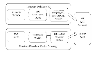
TABLE 1
MODULATION/CODING SCHEMES SUPPORTED BY WIMAX [1]
Fig. 1. BWA System Development.
The most important similarity between LTE and Wi- MAX is orthogonal frequency division multiplex (OFDM) signaling. Both technologies also employ Viterbi and tur- bo accelerators for forward error correction. From a chip designer's perspective, that makes the extensive reuse of gates highly likely if one had to support both schemes in the same chip or chip-set. From a software defined radio (SDR) perspective, the opportunity is even more enticing. Flexibility, gate reuse and programmability seem to be the answers to the WiMAX-LTE multimode challenge.
2.2 Hypothesis of AMC
In traditional communication systems, the transmission is designed for the "worst case" channel scenario thus, coping with the channel variations and still delivering an error rate below a specific limit. Adaptive transmission schemes, how- ever, are designed to track the channel quality by adapting the channel throughput to the actual channel state. These techniques take advantage of the time-varying nature of the wireless channel to vary the transmitted power level, symbol rate, coding scheme, constellation size, or any combination of these parameters, with the purpose of improving the link average spectral efficiency (bits/s/Hz).

is that cells should be much less sensitive to overload and cell size shrinkage during the load than before. Ideally, customers at any range should receive solid QoS without drops that 3G technology may experience.
Fig. 2. AMC Cell
IJSER © 2011 http://www.ijser.org
International Journal of Scientific & Engineering Research Volume 2, Issue 5, May-2011 3
ISSN 2229-5518
3.2 System Architecture
3.2.1 Basic Wimax
The model for the WiMAX is build from the standard documents [1, 2] as follow;
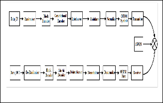
Fig. 3. BWA System Components
3.2.2 Cognitive Engin
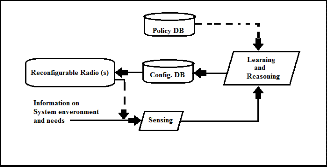
When the basic system successfully built and tested, a cog- nitive engine (CE) must develop to automatically direct the SDR to load and execute the appropriate profile. The CE refer to predefined polices, while continuously sensing the channel situation. Then, perform its logic to pick up the suit- able configuration to execute it in the SDR system.
Fig. 4. Cognitive Mechanism
4 ADAPTIVE COMMUNICATION SYSTEM
4.1 AMC Architecture
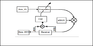
The function of AMC is based on SDR-CR combination. The receiver evaluate received packets (i.e. SNR or BER) to estimate the Channel Quality Indictor (CQI) module, then feedback the transmitter to reconfigure itself for the next packet send.
Fig. 5. Adaptive System
4.2 AMC System Performance
The performance of AMC highly depends on the accurate channel estimation at the receiver and the reliable feedback path between that estimator and the transmitter on which the receiver reports channel state information (CSI). In order to assure a high-quality implementation the next steps must be followed:
4.2.1 Channel Quality Estimation
The transmitter requires an estimate of the expected channel conditions for the next transmission interval. Since this knowledge can only be gained by prediction from past chan- nel quality estimations, the adaptive system can only operate efficiently in an environment with relatively slowly-varying channel conditions. Therefore, the delay between the quality estimation and the actual transmission in relation to the maximal Doppler frequency of the channel is crucial for the system implementation since poor system performance will result if the channel estimate is obsolete at the time of transmission.
4.2.2 Parameter adaptation
The choice of the appropriate modulation and coding mode to be used in the next transmission is made by the transmit- ter, based on the prediction of the channel conditions for the next time interval. An SNR threshold such that it guarantees a BER below the target BER (BER0), is defined by the sys- tem for each scheme whenever the SNR is above the SNR threshold.
4.2.3 Feedback Mechanism
Once the receiver has estimated the channel SNR, converted it into BER information for each mode candidate, and, based on a target BER, selected the mode that yields the largest throughput while remaining within the BER target bounds, it has to feed back the selected mode to the transmitter in order that the adaptation can be performed.
However, the challenge associated with adaptive modulation and coding is that the mobile channel is time- varying, and thus, the feedback of the channel informa- tion becomes a limiting factor. Therefore, the assumption of a slowly-varying as well as a reliable feedback channel is necessary in order to achieve an accurate performance of the AMC scheme. In this way, no delay or transmission error can occur in the feedback channel so that no discre- pancy between the predicted and the actual SNR of the next frame appears. Moreover, the receiver must also be informed of which demodulator and decoding parame- ters to employ for the next received packet.
5 SIMULATION RESULTS
5.1 Functionality
A single function the can give different modulation order from BPSK to M-QAM (M= 2n, where n = 2,4,6,...) imple- mented in Matlab. The function called with the modulation order and the SNR in dB as input, then its plot the constella-
IJSER © 2011 http://www.ijser.org
International Journal of Scientific & Engineering Research Volume 2, Issue 5, May-2011 4
ISSN 2229-5518
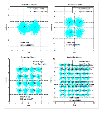
tion and calculates the BER.
Fig. 4. AMC Constalation Diagrams
5.2 BER vs. SNR
BER is the number of error bits occurs within one second in transmitted signal. BER defined mathematically as follow;

Number of Bits with Error
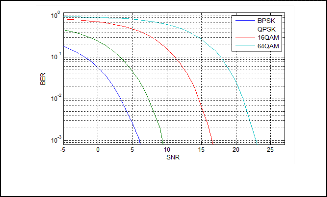
BER = Total Number of Bits Transmited (1)
6 CONCLUSION
The function implemented in this paper demonstrates the ability of converge AMC concepts in a single Matlab file. Tests show that all measured can be compared with the hardware model in terms of functionality and system per- formance. This component can be reused against a defined standard, IEEE 802.1 6e, LTE, or other BWA. The second part of the paper (Part II) will implement other system com- ponent related to coding both for source and channel. In the future this model can be expanded to include the compo- nents of the upper layers and a complete end to end BWA system could be built.
REFERENCES
[1] IEEE 802.16-2006: "IEEE Standard for Local and Metropolitan Area Networks - Part 16: Air Interface for Fixed Broadband Wireless Access Systems".
[2] ETSI TS 102 177 Version 1.3. 1, February 2006, "Broadband Ra- dio Access Networks (BRAN); HiperMAN; Physical (PHY) Layer"
[3] Practical Applications for Wireless Networks, Paris, 10 October,
2006, lET Workshop 2006.
[4] Douglas H. Morais, ‘UMTS’s LTE Webcast’, Adroit Wireless
Strategies, 16 Feb. 2010
[5] Muhammad Nadeem Khan, Sabir Ghauri, “The WiMAX
802.16e Physical Layer Model”,University of West England.
[6] Sami H. O., Mamoun M. A., “Software Defined Radio Ap- proaches on WiMAX Access Layer Design”, SUST, September
2009.
[7] Matthew Sherman, “IEEE Standards Supporting Cognitive Radio and Networks, Dynamic Spectrum Access, and Coexis- tence”, Electronics & Integrated Solutions, July, 2008.
[8] Kuo-Hui Li, PhD, “IEEE 802.16e-2005 Air Interface Overview”, WiMAX Solutions Division, Intel Mobility Group, June 05,
2006.
Fig. 4. Simulation BER vs. SNR
When the transmitter and receiver’s medium are good in a particular time and Signal-to-Noise Ratio is high, and then Bit Error rate is very low. In our thesis simulation we generated random signal when noise occurs after that we got the value of Bit error rate.
Signal Power
Signal Amplitude 2


SNR = Noise Power = Noise Amplitude
(2)
IJSER © 2011 http://www.ijser.org