International Journal of Scientific & Engineering Research Volume 2, Issue 9, September-2011 1
ISSN 2229-5518
Implementation of Generic Algorithm Using VHDL
on FPGA
Prashant Sen *, Priyanka Pateriya **
Abstract— Architecture. The development of a flexible very-large-scale integration (VLSI) for GA has been proposed in this paper. For the hardware architecture, we has develop on a random number generator (RNG), crossover, and mutation based on flexibility structure. This structure can dynamical- ly perform to the 3 types chromosome encoding: binary encoding, real-value encoding, and integer encoding. The overall structures has been designed and synthesized by VHDL (VHSIC hardware description language), simulation by ModelSim program, and then implemented on FPGAs (Field program- mable gate arrays). This hardware architecture that our design work very well flexible for the 3 groups problem examples: combinatorial optimization
problems, function optimal problems.
1 INTRODUCTION
—————————— ——————————
Genetic algorithms (GA) are techniques used to find exact or approximate solutions to optimization and search problems its algorithmic structure is simple. In Figure 1 each of the block modules performs a simple operation: (i) the fitness module performs the evaluation of the chromosome, (ii) the sequencer module randomly selects the chromosomes, i.e. an aspect of the model under study, and passes them to the selection mod- ule, (iii) the selection module decides which of the sequenced module should advance, and (iv) the mutation and crossover modules mutate and mate the selected chromosomes. The need for hardware implementation of GAs arises from the vast computational complexity of problems that cause delays in the optimization process of software implementations. The speed advantage of hardware and its ability to parallelize, offer great advantages to genetic algorithms to overcome those problems. Speedups of 1 to 3 orders of magnitude were achieved when frequently used software routines were implemented in hardware with Field Programmable Gate Arrays (FPGAs). However, those implementations were focusing on solving one specific problem due to the hardware resources con- straints This paper is organized as follows. Section II,describes basics of GA and classification of the chromosomes encoding. Section III, proposed GA hardware architectures. Section IV, discusses the simulation result. Section V, is conclusion
A. The Basics of GA
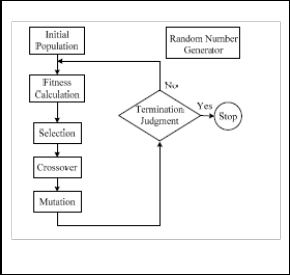
In general, the step of GA operations consists of 6 main steps: population initialization, fitness calculation, selection, crossover, mutation and termination judgment, is shown in Fig.2. In the beginning, the initial population of a GA is generated random- ly. Then, the evaluation values of the fitness function for the individuals in the current population are calculated. And then, the 3 steps of GA operators: selection, crossover, and mutation are performed. Finally, the termination criterion is checked, and the whole GA procedure stops if the termination criterion is reached. Our design and develop hardware in the GA process conclude RNG operation, crossover operation, and mutation operation.
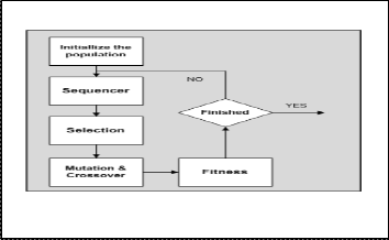
Fig2 Flow Chart of GA Process
Fig1 Genetic Algorithm Flowchart
————————————————
*Department Of Computer Science & Engg.B.T.Institute Of Research & Technology Sagar M.P. India E-mail: prashantsen@yahoo.com
**Department Of Electronics & Communication Engg.B.T.Institute Of
Research & Technology Sagar M.P. India, E-mail: ppateriyaec@yahoo.co.in
B. Classifications of the Chromosome Encodings
In this paper, we have classified the chromosome encoding ac- cording to the most prefer are 3 types compose of: binary encod- ing, real-value encoding, and integer encoding, that can describe are as follow:
1) Binary encoding: In binary encoding, every chromosome is a string of bits only „0‟ and „1‟. For example “[11001110], [11100101]”
Crossover operation: Used in selection of the genes from parent chromosomes and creates a new issue. The simplest way how to
IJSER © 2011
http://www.ijser.org
International Journal of Scientific & Engineering Research Volume 2, Issue 8, August-2011 2
ISSN 2229-5518
do this is to choose randomly some crossover point and every- thing before this point copy from a first parent and then every- thing after a crossover point copy from the second parent.
Mutation operation: After crossover performed, mutation take place. This is to prevent falling all solutions in population into a local optimum of solved problem. Mutation changes randomly the new issue. Which, can switch a few randomly chosen bits from „1‟ to „0‟ or from „0‟ to „1‟. For example “[ 1 1 0 1 0 1 1 ] => [ 1
1 1 1 0 1 0 ]”
2) Real-value encoding: Is the best used for function optimization problem. It has been widely confirmed that real value encoding performs better than binary encoding. In a real value encoding, every chromosome is a string of some value. The values can be anything connected to problem, from numbers, real numbers. For example “[1.23 2.47 3.21], [ABCDEF], [(right), (left)]”
Crossover operation: All crossovers from binary encoding can be used.
Mutation operation: Adding a small number to selected values is added (or subtracted). For example “(6 2.86 4.11 5.47) => (6 2.73
4.22 5.47)”
3) Integer encoding: In integer encoding, every chromosome is a string of numbers, which represents number in a sequence. For example “[1 5 8 3 2 4 6 3 10], [10 2 5 9 6 4 1 3 8]”
Crossover operation: One-point crossover is selected, till this point the integer is copied from the first parent, then the second parent is scanned and if the number is not yet in the offspring it is added. For example “(1 2 3 4 5 6 7 8 9), (4 5 3 6 8 9 7 2 1) => (1 2 3 4
5 6 8 9 7)”
Mutation operation: Order changing, two numbers are selected
and exchanged. For example “(1 2 3 4 5 6 8 9 7) => (1 8 3 4 5 6 2 9
7)”
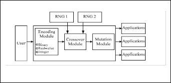
A basic idea in this work is to implement the hardware architec- tures of RNG ( random number generation), crossover, and muta- tion. Because the 3 architecture are depend on the encoding oper- ation. Difference encoding operation requires difference crossov- er and mutation. So, this hardware architecture design based on flexibility to the 3 types encoding for working together at a time. However the main drawbacks of hardware design are difference operation of crossover and mutation in each encoding. The main process of 3 hardware architecture are the users can choose any one of 3 type encoding according to the requirement of various GA applications, is shown in Fig 3.
III. PROPOSED HARDWARE ARCHITECTURE FOR GA
In this paper, we have design and develop the 3 hardware architecture of the GA process, that concluding: random num- ber generator module, crossover module, and mutation mod- ule, are as follow:
A. Random Number Generator Module
We have to take advantage of linear feedback shift register
(LFSR) for random number generated. The operation of LFSR
are generated by D flip-flop, is show in Fig. 4. And a first bit
(X0) to take XOR with a last-bit (Xn) represent feedback, that is repeat process many time. as following the equation (1).
X0(n +1) = Xn(n) + X0(n)…………………. (1)
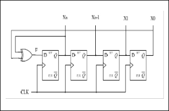
When X0(n +1) represent as data bit 0 at clock time (n +1), X0(n) represent as data bit 0 at clock time (n), and Xn(n) represent as data bit n at clock time (n).
Fig4 Hardware of RNG Module
B. Crossover Module
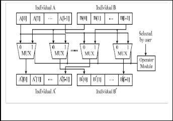
The crossover module is used to perform the crossover opera- tions on the two winner individuals, which are denoted A and B. The operator module offers, four crossover operations, in- cluding uniform, single-point, two-point, and cross-point. This crossover can use flexible to binary encoding, real-value en- coding, and integer encoding. Users can choose any one of them according to their needs. The output chromosomes, which are denote A' and B', are then sent to the following mu- tation module, is show in Fig. 5.
Fig 3 A Basic Idea
Fig 5 Hardware of Crossover Module
IJSER © 2011
http://www.ijser.org
International Journal of Scientific & Engineering Research Volume 2, Issue 8, August-2011 3
ISSN 2229-5518
C. Mutation Module
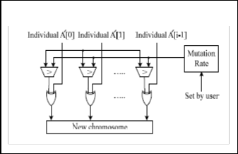
The mutation module is used to avoid converging to the local optimization and instead locate the better solutions. A flexible mutation rate setting scheme is used. This mutation can use flexible to binary encoding, real-value encoding, and mutation encoding. User can easily choose an appropriate mutation rate according to their needs. In the design, the mutation operation is performed when the user-defined mutation rate exceeds the threshold, and it is also used to generate the new chromo- some. Finally, the generated chromosome is into the popula- tion initialization, is show in Fig. 6
Fig 6 Hardware of Mutation Module
for design and reduce a cost for hardware implementation.
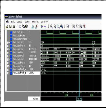
The simulation of crossover module, is show in Fig. 8. After the
random number generated. The crossover operation are per-
formed. In this example simulation for the binary encoding and real-value encoding can used. The VHDL code have to design for
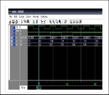
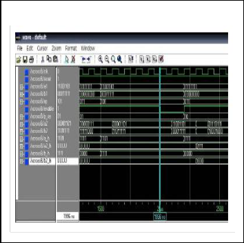
binary number = 8-bit, crossover point = 3 bit, integer n = 7. The simulation of mutation module, is shown in Fig. 9. This simula- tion is an example of binary encoding and integer encoding. The VHDL code design is one-point mutation, integer n = 7, for bi- nary number = 8 bit, and mutation point = 3 bit. The experimen- tal results, we have compare our design with, which the flexible to finding the minimum-maximum of the complex function. Which has only real-value encoding.
Fig 7 Simulation of RNG Module
IV. SIMULATION AND RESULTS
The 3 groups problems, that is depend on the three types encod- ing have been experimental in this work. The group problems are as follow: Group#1, is combinatorial optimization problems, that compose of knapsack problem, minimum spanning tree problem, and set-covering problem. They have chromosome encoding to binary number. Group#2, is function optimal problems that is searching to max-min of the complex function, which has chro- mosome encoding as real value number. For example “find the maximum of a 1-d trigonometric function, and find the minimum of a 2-d Schubert function). Group#3, is path planning optimiza- tion problems This problem is about to find the optimal part from start point to final point. For example “find a optimal part of traveling salesman problem, and find a optimal part planning of a robot machine. The simulation result, we can used ModelSim program and VHDL code to design and synthesized. The simula- tion of RNG module is show in Fig. 7. The output can separate to three part: q1 represent binary output, q2 represent integer out- put, and q3 represent real-value output. The integer range -1 to
255, binary 8-bit, number of array equal to 36. For the VHDL code to design for RNG, we can used function in package
“std_logic_unsigned” is
conv_ integer (arg : std_logic_vector) return integer;
and converse from integer to “std_logic_vector” can used
function in package “std_logic_arith” is conv_std_logic_vector (arg : integer; size : integer) return std_logic_vector;
and take 2‟complement for conversion binary to real-number, and then conversion from real-number to integer respectively. So,
the advantage of RNG module in this work is not use much time
Fig 8 Simulation of Crossover Module
IJSER © 2011
http://www.ijser.org
International Journal of Scientific & Engineering Research Volume 2, Issue 8, August-2011 4
ISSN 2229-5518
Fig 9 Simulation of Mutation Module
The 3 architectures have been designed using VHDL and then it is synthesized and verified. For the simulations, we used the ModelSim program and implementation will be on FPGAs. The GA requires very intensive computations to perform op- timization. Hence, a dedicated VLSI implementation is neces- sary. All of most, a hardware GA requires very flexible to var- ious applications. We have proposed development of a flexible hardware core for GA.
References
1. T. Tatsuhiro, M. Yoshihiro, S. Naoki, Y. Keiichi, and I.
Minoru, “Flexiblen Implementation of Genetic Algo-
rithm on FPGAs”, IEEE Int.Conf., 2008.
2. P. Vipapun and K. Pinit, “A High-Speed Hardware of the Geneticn Algorithm for Combinatorial Optimiza- tion Problem”, in Proc.3rd IEEE Int. Conf. on Com- munication and Information Technology, vol. 2, Sep- tember 2003.
3. N. Shruthi and P. Carla, “Hardware Implementation of the Genetic Algorithm Modules for Intelligent Sys- tem”, IEEE Int. Conf., 2005.
4. F. Pradeep, S. Hariharan, K. Srinivas, K. Didier, S.
Adrian, Z. Ricardo, and R. Ramesham, “A Customiz-
able FPGA IP Core Implementation of a General Pur-
pose Genetic Algorithm Engine”, IEEE Int. Conf.,
2008.
5. J. Yutana and C. Prabhas, “Cellular Compact Genetic Algorithm for Evolvable Hardware”, IEEE Int. Pro. of ECTI-CON, 2008.
6. G. Xianyue, L. Hongyan, and W. Shufeng, “A Dynam- ic Byte Encoding Genetic Algorithm for Numerical Optimization”, IEEE Int. Conf. 3rd on Innovative Computing Information and Control(ICICIC‟08),
2008.
7. D. Yuan-Ming and W. Xuan-Yin, “Real-coded adap- tive genetic algorithm applied to PID parameter op- timization on a 6R manipulators”, IEEE Int. Conf. 4th on Natural Computation, 2008.
8. M. Mansouri, M. Aliyari Shoorehdeli, and M. Tesh- nehlab, “Integer GA for Mobile Robot Path Planning with using another GA as Repairing function”,IEEE Int. Conf. on Automation and Logistic, September
2008.
————————————————
Prashant Sen B.E. (CSE), MTECH (IT),
. E-mail: prashantsen@yahoo.com
Priyanka Pateriya B.E.(ECE) MTECH (pursuing), E-mail: ppateriyaec@yahoo.co.in
IJSER © 2011
http://www.ijser.org