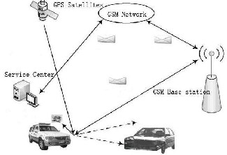
FIG 1, SYSTEM COMPOSITION
The research paper published by IJSER journal is about Image processing based vehicle tracking system using ARM7 1
ISSN 2229-5518
Image processing based vehicle tracking system using ARM7
Lalitha.S1, Ashwini.V2, Madhusudhan.K.N3
Abstract— The intelligent system for theft vehicle detection is It’s own requirement in the current society. The intelligent system wha t we are trying to build consists of ARM 7 controller as the main core along with this, the other supporting modules which is used are GSM,GPS,A LCD for the instant display of the axis information. The development of the embedded software provides a good platf orm for the better working of the hardware. The entire concept begins with the image capturing of the number (license) plate of the vehic le and processing of that image by using matlab, and providing the output to the ARM 7 for the further processing. Number plate distinguishing and its processing along with the supporting modules met the traffic auditing department’s needs about Mobile Vehicle Checkin g..
.
—————————— ——————————
I. INTRODUCTION
Now a day every country is spending huge economy in the case of traffic automation and vehicle theft controlling [1]. This is be- cause of the enormous increase in the vehicles on roads. Vehicle checking way has some faults such as leak checking, false check- ing, So in order to avoid such situation the intelligent system for the traffic surveillance is required and this system is built to meet this kind of requirement and replace he traditional way of find- ing the theft vehicle or any black listed vehicle in its own way.
The most vital and the most difficult part is the detection and ex- traction of the vehicle Number plate[2], which directly affects the systems overall accuracy. The image processing technology[5] is used for the extraction of number plate The presence of noise, blurring in the image, uneven illumination, dim light and foggy conditions make the task even more difficult.
II. SYSTEM COMPOSITION
This system is based on ARM 7 controller along with the further pro- cessing modules. An image of number plate is extracted from the camera output which is in the video fomat.The extracted image is given for the embedded environment for the further processing. After the processing of data, the details are sent to the GSM module if the license plate data matches the blacklisted license plate. Fig 1 gives the details about the working of the entire module.
A. VIDEO CAPTUR E
When the system works, the camera in the front of the car collects the data automatically and saves it in video buffer. In this work a webcam is used for video capture[3] but practically a high definition camera is required.
B. Vehicle Plate Recognition
Data from camera will be sent to the PC. Video capturing[5] is done by PC and image processing is done by using MATLAB. In MATLAB a bitmap image is converted to text and save it in .text format.
--------------------------------------------------------
Lalitha.S is currently working as assistant Professor in the Dept of ECE,
C. Communication (GSM)
The vehicle checking terminal communicates with the server center by the SMS message on the GSM net. GSM is a cellular network, which means that mobile phones connect to it by searching for cells in the immediate vicinity.
D. Global Positioning System
The system can correctly send the position and time of the checking vehi- cle to the server center by GPS positioning, therefore, the terminals can be coordinated properly
FIG 1, SYSTEM COMPOSITION
Intelligent mobile vehicle checking system is composed of ARM7 micro-
[5]
BMSCE,Bangalore and also pursuing PhD degree program in Image processing
processor (LPC 2103), video capturing unit
, GPS positioning module
in SV University, Tirupathi,India,PH-+919886252648
Email:lalithaamogh@rediffmail.com
Ashwini V, is currently working as assistant Professor in the Dept of ECE,
BMSCE,Bangalore Ph-+919538026421, E-mail:ashwinigargi03@gmail.com
Madhusudhan.K.N, is currently working as assistant Professor in the Dept of
ECE, BMSCE,Bangalore Ph-+919845409693, E-mail: krgirimadhu@gmail.com
GPS-634R, wireless telecommunication module SIM 300 and remote
control receiver. The detailed hardware composition is shown in figure 2.
IJSER © 2012
http://www.ijser.org
The research paper published by IJSER journal is about Image processing based vehicle tracking system using ARM7 2
ISSN 2229-5518
LPC2103 Microcontroller
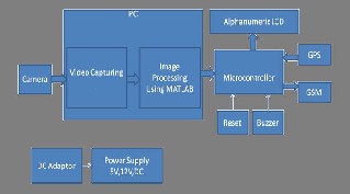
The ARM7TDMI-S[1] is a 32-bit microcontroller based on RISC archi- tecture. It offers high performance for low power consumption. It uses 3 stage pipeline to increase the speed of the flow of instruction. The 3 stages are fetch, decode and execute. Text Font of Entire Document
Figure 2.1: VIDEO CAPTURING SYSTEM FUNCTION
.
A.VIDEO CAPTURING SYSTEM FUNCTION
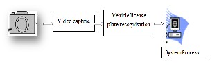
When the system works, the camera in the front of the car collects the data normally the data will be the license plate only and saves it in the video buffer. In this work a webcam is used for video capture but practically a high definition camera required. The data captured will be sent to the MATLAB for the further processing.In details the process is shown in the fig below.For an example, Night Vision Camera.Night vision is the ability to see in a dark environment. Whether by biological or technological means, night vision is made possible by a combination of two approaches: sufficient spectral range, and sufficient intensity range. Humans have poor night vision compared to many animals, in part because the human eye lacks a tapetum lucidum.
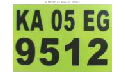
Figure2.2: Vehicle Plate Recognition
Figure 2.2.1 The Dubai police use three Petards ANPR cameras to monitor vehicles in front and either side of the patrol car
Data from camera will be sent to the PC. Video capturing is done by PC and image processing is done by using MATLAB. In MATLAB a bitmap image is converted to text and save it in .text format. Image captured from the camera is first converted to the binary image consisting of only 1’s and
0’s (only black and white). By thresholding the pixel values of 0 (black) for
all pixels in the input image with luminance less than threshold value and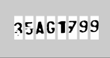
1 (white) for all other pixels. The image is processed along vertical and horizontal runs (scan-lines). If the number of white pixels is less than a desired threshold or greater than any other desired threshold, white pi xels are converted to black. In this system, threshold values are selected as 10 and 100 for both horizontal and vertical smearing. If number of ‘white’ pixels < 10 ; pixels become ‘black’ Else ; no change If number of ‘white’ pixels > 100 ; pixels become ‘black’ Else ; no change, in this a image is converted to binary image.In the segmentation of plate characters, license plate is segmented into its constituent parts obtaining the characters indi- vidually. Firstly, image is filtered for enhancing the image and removing the noises and unwanted spots. After this operation, horizontal and verti- cal smearing is applied for finding the character regions. The result of this segmentation is in Figure 2.3
Figure 2.3 Result of segmentation
B.1 Character Recognition
B. Vehicle Plate Recognition
Before recognition algorithm[6]
, the characters are normalized. Normalization
Recent advances in technology have taken automatic number plate recog- nition (ANPR)[2] systems from fixed applications to mobile ones. Scaled- down components at more cost-effective price points have led to a record number of deployments by law enforcement agencies around the world. Smaller cameras with the ability to read license plates at high speeds, along with smaller, more durable processors that fit in the trunks of police vehicles, allow law enforcement officers to patrol daily with the benefit of license plate reading in real time, when they can interdict immediately. Despite their effectiveness, there are noteworthy challenges related with mobile ANPRs. One of the biggest is that the processor and the cameras must work fast enough to accommodate relative speeds of more than
100 mph (160 km/h), a likely scenario in the case of oncoming traffic. This
equipment must also be very efficient since the power source is the vehicle battery, and equipment must be small to minimize the space it requires.
is to refine the characters into a block containing no extra white spaces (pixels) in
all the four sides of the characters.
For matching the characters with the database, input images must be equal-sized with the database characters. Here the characters are fit to 36 × 18. The extracted characters cut from plate and the characters on database are now equal-sized. The next step is template matching. Tem- plate matching is an effective algorithm for recognition of characters[4]. The character image is compared with the ones in the database and the best similarity is measured. To measure the similarity and find the best match, a statistical method correlation is used. Correlation is an effective technique for image recognition which was developed by Horowitz. This method measures the correlation coefficient between a number of known images with the same size unknown images or parts of an image with the highest correlation coefficient between the images producing the best match. There are two forms of correlations: auto-correlation and cross-
correlation.
IJSER © 2012
http://www.ijser.org
The research paper published by IJSER journal is about Image processing based vehicle tracking system using ARM7 3
ISSN 2229-5518
B.2 Algorithms
There are six primary algorithms that the software requires for identifying a license plate:
1. Plate localization[5] – responsible for finding and isolating the plate on the picture.
2. Plate orientation and sizing – compensates for the skew of the plate and adjusts the dimensions to the required size.
3. Normalization – adjusts the brightness and contrast of the im- age.
4. Character segmentation – finds the individual characters on the plates.
5. Optical character recognition.
6. Syntactical/Geometrical analysis – check characters and posi- tions against country-specific rules.
The complexity of each of these subsections of the program determines the accuracy of the system. During the third phase (normalization), some systems use edge detection techniques to increase the picture difference between the letters and the plate backing. A median filter may also be used to reduce the visual noise on the image.
B.3 Difficulties
There are a number of possible difficulties that the software must be able to cope with. These include:![]()
Poor image resolution, usually because the plate is too far away but sometimes resulting from the use of a low-quality camera.
Blurry images, particularly motion blur.
ed States). In rare cases the 400 and 450 MHz frequency bands are as- signed in some countries because they were previously used for first- generation systems. Most 3G networks in Europe operate in the 2100 MHz frequency band.
You can use AT Commands "AT" meaning attention , to communicate with the SIM card. The SIM interface supports the functionality of the GSM Phase 1 speci- fication and also supports the functionality of the new GSM Phase 2+ specifica- tion for FAST 64 kbps SIM (intended for use with a SIM application Tool-kit).
The "AT" or "at" prefix must be set at the beginning of each command line.
To terminate a command line enter <CR>.
Commands are usually followed by a response that includes
”<CR><LF><response><CR><LF>”.
Testing and General commands for GSM
Steps to test the GSM Module
We can use the PC Hyper Terminal to interact with the GSM Module. First insert the SIM card to the GSM Module,
Connect the Serial cable –RS232 to the PC via DB9 pin connector on the GSM Module.
Give the power supply. The power supply indicating LED will be ON continuou s-
ly.
Another LED on the Module starts blinking to indicate the availability of ne t- work.
If the network is available then the delay between the blinking is less.
If the network is not available then the delay between the blinking is more. Each GSM modem will have a unique id called IMEI.
Open Hyper Terminal in the PC , apply the below settings
Connect using Bits per second | | COM1 9600 | |
Data bits | | 8 | |
Parity Stop bits Flow control | | 1 | None None |
Type AT on HyperTerminal and press ENTER OK will be display as a re- sponse from the GSM Module.
AT OK
Poor lighting and low contrast due to overexposure, reflection
or shadows.
An object obscuring (part of) the plate, quite often a tow bar, or dirt on the plate.
A different font, popular for vanity plates (some countries do not allow such plates, eliminating the problem).
Circumvention techniques.
Lack of coordination between countries or states. Two cars from different countries or states can have the same number but dif- ferent design of the plate.
C. Communication Function
The vehicle checking terminal communicates with the server center by the SMS message on the GSM net. GSM is a cellular network, which means that mobile phones connect to it by searching for cells in the immediate vicinity. There are five different cell sizes in a GSM network— macro, micro, pico, femto and umbrella cells. The coverage area of each cell varies according to the implementation environment.
GSM networks operate in a number of different carrier frequency ranges with most 2G GSM networks operating in the 900 MHz or 1800 MHz bands. Where these bands were already allocated, the 850 MHz and
1900 MHz bands were used instead (for example in Canada and the Unit-
Below are few more commands and response from the Module
AT+CGMI - To check Manufacturer Identification
FLYFOT M260 MODEM
OK
AT+CGMM
MULTIBAND 900 1800 1900
OK
D. Global Positioning System
The system can correctly send the position and time of the chec k- ing vehicle to the server center by GPS positioning, therefore, the termi- nals can be coordinated properly.
The Global Positioning System (GPS) is a space-based global
navigation satellite system (GNSS) that provides location and time infor- mation in all weather, anywhere on or near the Earth, where there is an unobstructed line of sight to four or more GPS satellites GPS tracking is not always possible. Global Positioning System (GPS) indicates that the system can be used everywhere on Earth, on land, at sea and in the air. A GPS device receives signals from the GPS satellites, high in the sky. If it receives strong enough signals from three or more different satellites, it can calculate its position. As these signals are very weak, in some circum- stances it can be difficult to receive even three different signals. This is the case in towns with high buildings and relatively narrow streets or under trees with thick foliage. Under these conditions real-time GPS tracking could be troublesome. GPS tracking inside buildings is seldom poss ible. A GPS device does NOT send any signal, not to the GPS satellites, nor anywhere else. It can only receive. So, if we want to know where the GPS
IJSER © 2012
http://www.ijser.org
The research paper published by IJSER journal is about Image processing based vehicle tracking system using ARM7 4
ISSN 2229-5518
device is, we will need a second technology to send this information to us. For this we often use a cellular network. This means that a GPS tracking device must at least contain a GPS receiver and a cellular phone modem.
Below are the characters obtained from GPS receiver per second. The GPGGA protocol indicates the respective time, latitude and longitude value.
$GPGGA,111035.941,1255.4726,N,07729.0316,E,1,10,0.9,807.1,M,-
85.3,M,,0000*79
$GPGSA,A,3,10,02,26,27,09,17,04,28,05,08,,,1.8,0.9,1.5*38
$GPGSV,3,1,12,02,67,253,41,04,64,016,24,27,41,288,40,10,36,152,46*7B
$GPGSV,3,2,12,28,35,106,24,09,34,299,34,17,23,040,30,05,15,189,25*7B
$GPGSV,3,3,12,08,11,159,25,26,10,211,42,15,04,237,,12,04,321,*78
$GPRMC,111035.941,A,1255.4726,N,07729.0316,E,001.2,032.4,280810,,,A*6B
$GPVTG,032.4,T,,M,001.2,N,002.2,K,A*0B
The colored region gives the time value that is picked and stored.
------------------------------------------------------------------------------------
$GPGGA,111035.941,1255.4726,N,07729.0316,E,1,10,0.9,807.1,M,-
85.3,M,,0000*79
$GPGSA,A,3,10,02,26,27,09,17,04,28,05,08,,,1.8,0.9,1.5*38
$GPGSV,3,1,12,02,67,253,41,04,64,016,24,27,41,288,40,10,36,152,46*7B
$GPGSV,3,2,12,28,35,106,24,09,34,299,34,17,23,040,30,05,15,189,25*7B
$GPGSV,3,3,12,08,11,159,25,26,10,211,42,15,04,237,,12,04,321,*78
$GPRMC,111035.941,A,1255.4726,N,07729.0316,E,001.2,032.4,280810,,,A*6B
$GPVTG,032.4,T,,M,001.2,N,002.2,K,A*0B
The colored region gives the latitude position of the module, that is picked and stored.
-----------------------------------------------------------------------------------------------
$GPGGA,111035.941,1255.4726,N,07729.0316,E,1,10,0.9,807.1,M,-
85.3,M,,0000*79
$GPGSA,A,3,10,02,26,27,09,17,04,28,05,08,,,1.8,0.9,1.5*38
$GPGSV,3,1,12,02,67,253,41,04,64,016,24,27,41,288,40,10,36,152,46*7B
$GPGSV,3,2,12,28,35,106,24,09,34,299,34,17,23,040,30,05,15,189,25*7B
$GPGSV,3,3,12,08,11,159,25,26,10,211,42,15,04,237,,12,04,321,*78![]()
$GPRMC,111035.941,A,1255.4726,N,07729.0316,E,001.2,032.4,280810,,,A*6B N,002.2,K,A*0B
the longitude position of the module, that is
IV. SOFTWARE DESIGN
The software of the new intelligent mobile vehicle checking sys- tem includes two parts, the remote-server center software and embedded terminal software. The development of the software is based on ADS inte- grated development environment.
Functions of the system software:
The server center saves the data library which contains the newest vehi- cles in the ‘black list’, account numbers, mobile numbers. The video ca p- ture software collects the video data and changes its format, and then the video capture software sends the data to the identification buffer. Date is sampled and sent to the vehicle checking software. The vehicle checking software identifies the vehicle license and compares it with the data in the SD card. If the car is the one which breaks the rules, the software displays the information of the car (include the license of the car, the name of the car and its owner). If the information is not in the SD card, the soft will enquire the server center and send the result to terminal.if the information of the car matches with the black list then the car found time and its posi- tion in terms of longitude and latitude is send via SMS to relative officer number. Using the identified plate number the toll fee can be deducted and if the vehicle carrying overload the penalty can also be deducted from
his account number.
IV.I Software Components Used
1. MATLAB version 7.8.0 (R2009a)
2. Embedded C
3. Keil Compiler
4. Flash Magic
V.RESULTS AND FUTURE ENHANCEMENT
MATLAB Image Processing Outputs
The Extracted single alphabet image which will then be co n- verted into characters through image correlation. Figure5.1 shows the MATLAB output
The Extracted single alphabet image which will then be co n-
verted into characters through image correlation. Figure5.1 shows the
MATLAB output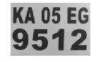
INPUT IMAGE-CAPTURED
GRAY-SCALE EQUIVA-
LENT
BINARY EQUIVALENT IMAGE
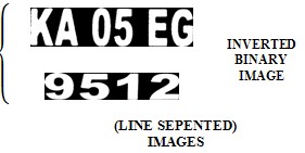
Figure5.1 MATLAB output image
Future Enhancement
The system can be enhanced by using high definition camera for high quality video capture. It can be used for the application of over load checking , toll free collection and many more.Using the high ranged qual i- ty load cell and Weigh-in motion(WIM) technology enhancement to intel- ligent transportation systems (ITS) can be made.WIM has proven effective in measuring dynamic wheel forces of moving vehicles. It allows vehicles to be weighed as they are moving across the scale at speeds from 5 -80 mph.
IJSER © 2012
http://www.ijser.org
The research paper published by IJSER journal is about Image processing based vehicle tracking system using ARM7 5
ISSN 2229-5518
On using vehicle and driver’s information, Under Vehicle Inspection Sys- tem (UVIS) can be developed, the UVIS software will automatically pop u- late the information for future visits, saving the user valuable inspection time. With this information, the user can then determine how many times the vehicle has been at their location and can determine if the vehicle is on a “Hit List.” If a vehicle appears on a hit list, the software will then alert the user, provide a reason for the alarm and can email anyone wishing to be notified of the vehicle’s presence. These lists can be imported from external sources such as spreadsheets.
VI.CONCLUSION
The intelligent mobile vehicle checking system uses the detec- tion technique of video capture, the wireless communication technique, emergency indication, meets the traffic auditing department’s needs about Mobile Vehicle Checking. The system has the advantages of small size, low costs, full-featured and powerful expansibility. The main aim of the project to develop an intelligent and sophisticated mobile vehicle checking system that could keep-up with fast infrastructural growth and road in- frastructure development was achieved. This system proved to be much more efficient and produced good results.
ACKNOWLEDGMENT
The study was supported by Intelligent vehicle checking system based on ARM7, IEEE paper 2010, Lihe, College of Information Engineering,Inner Mongolia University of Technology Hohhot�China. Lvfang, College of Information Engineering,Inner Mongolia University of Technology
[1] Inigo R.M., Application of machine vision to traffic monitoring and control, IEEE Transactions on Vehicular Technology, 1989,
38(3):112-122.
[2] Lotufo R.A., Morgan A.D., Johnson A.S.Automatic number-plate recognition. Proceedings of image Analysis for transport applications, IEE Colloquium, 1990(6):1-6.
[3] Robert T.Collins, Alan J.Lipton, etal.A System for Video
Surveillance and Monitoring. Carnegie Mellon University, 2000.
[4] A.S. Johnson, B.M. Bird, 1990, “Number-plateMatching for Automatic Vehicle Identification,” IEE Colloquium on Electronic Image and Image Processing in Security and Forensic, Aprl, 1990.
[5] H.J. Choi, 1987, “A Study on the Extraction and Recognition of a Car Number Plate by Image Processing,” Journal of the Korea Institute of Telematics and Electronics, Vo1.24, pp. 309-3 15,1987.
[6] H.S. Kim, et al., 1991, “Recognition of a Car Number Plate by a Neural Network,” Proceedings of the Korea Information Science Society Fall Conference, Vol. 18, pp. 259-262, 1991
[7] Design of Intelligent Mobile Vehicle Checking System Based on ARM7 Lihe, College of Information Engineering,Inner Mongolia University of Tech- nology Hohhot�China. Lvfang, College of Information Engineering,Inner
Mongolia University of Technology
IJSER © 2012