the magnitude response
International Journal of Scientific & Engineering Research, Volume 5, Issue 4, April-2014 1598
ISSN 2229-5518
E-mail: ella4mneuter@yahoo.com
In this paper, an active band-pass R- filter output response at different values of center frequency using MAPLE programming is carried out. A sixth order active band pass R-filter are constructed at center frequencies of 10 kHz and 100 kHz and quality factors of 2, 5, 7, 8 and 10 and roll off rate of 20dB/decade. The architecture used is the multiple feedbacks. The filter parameters and values for the passive components were calculated, the gain and phase response were then simulated with MAPLE programming. The simulation shows that at high Quality factors, the bandwidth of the filter response reduces considerably while its frequency selectivity increases without a shift in its center frequency. This is an indication that the filter will function well at high frequencies and perform poorly at lower frequencies. This result also shows that the R-filter is most selective at a quality factor of Q=8 and centre frequency of fo = 100KHz Keywords: R-filter, Quality factor, Band pass, MAPLE.
IJSER © 2014 http://www.ijser.org
International Journal of Scientific & Engineering Research, Volume 5, Issue 4, April-2014 1599
ISSN 2229-5518
INTRODUCTION
A filter is defined as a network which passes a certain portion of a frequency spectrum and blocks the remaining portion of the spectrum. (Igwue, 2007).The term “blocking” means that
the magnitude response![]()
![]()
H ( jω)
of the filter is approximately zero for that frequency range. In
other words, a filter is a frequency –selective device or system. The active filter without the capacitor is called an active-R filter; and has received much attention due to its potential advantages in terms of miniaturization, ease of design and high frequency performance (Srinivasan 1992; Kadam & Mahajan 1995; Shinde & Mirkute 2003). It has been also pointed out in the literature that active-R networks offer substantially low sensitivity characteristics as compared to R-C active structures (Soderstand & Mitra 1971). Although several papers have been published on evaluation of the second order active-R filter, we have not come across any reported circuit regarding direct coupled circuit for realizing third-order active-R filters with feedforward input signals. This gives greater stop-band attenuation and sharper cut-off at the edge of the passband. The band-pass response is characterised by a frequency band between the lower cut off frequency, fL and upper cut off frequency, fH such that input signals with frequencies(f) within the band fL (i-e fL <f<fH ) less than f and f itself is less than fH (fL < f<fH ) emerge unchanged while those signals with frequencies outside the band are attenuated. The difference (fH - fL ) is called the bandwidth of the filter, and the point of frequency spectrum at which the band is centered is called the centre frequency fo (Sergio,F, 1988).
Filters are usually classified according to filtering range, frequency response in pass band, and circuit component. Classified by filtering range, there are four types of filters: low- pass, high-pass, band-pass, and band-reject filters. According to frequency response in pass band, there are two types: Butterworth and Chebyshev filters. According to circuit component, they are active and passive filters.
Passive filters are circuits that contain only passive components (resistors, inductors and capacitors) connected in such a way that they will pass certain frequencies while rejecting others. Active filters, which are the only type covered in this paper, employ active
components (transistors or operational amplifiers) plus resistors, inductors and capacitors. Active filters are widely used in modern communication systems, because they have the following advantages:
1. Because the transfer function with inductive characteristic can be achieved by particular circuit design, resistors can be used instead of inductors.
2. The high input impedance and low output impedance of the operational amplifier means that the filter circuit is excellent in isolation characteristic and suitable for cascade.
3. Because active components provide amplification, therefore active filters have gain.
METHODOLOGY
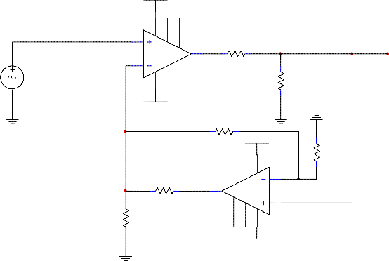
The circuit configuration for the sixth –order active R- Band pass filter was gotten from the work of Prabhat, U. and Pal, L. (2006) which is on the second order active Band pass filter as
shown in Fig 1. The resistor values were calculated using equation 1 and 2.
IJSER © 2014 http://www.ijser.org
International Journal of Scientific & Engineering Research, Volume 5, Issue 4, April-2014 1600
ISSN 2229-5518
CC
R1
V1
R2
VSS
R3
R4
VSS
R3
R2
VCC
Fig 1: Circuit diagram of a second order active R-band pass filter
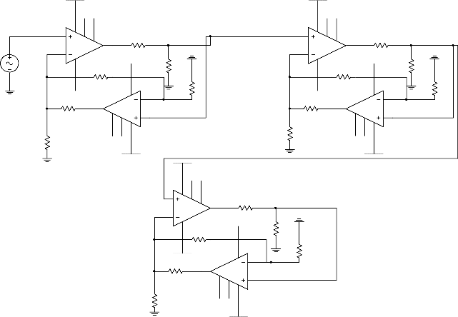
The architecture that has been used to implement both the sixth order active R-band-pass filter is the multiple feed-back topology which can be realized through cascading of the second order filter stages. The circuit diagram in Fig. 2 shows the implemented circuit composed of triply
cascaded second order active R-band pass filter.
Analysis
R 4 =![]()
k1 × R3
(1)
(1 − k1 )
R 2 =![]()
k2 × R1
(2)
(1 − k2 )
Since k1 and k2 are attenuators, their values are given as
1
![]()
k1 =
Q
(3)
IJSER © 2014 http://www.ijser.org
International Journal of Scientific & Engineering Research, Volume 5, Issue 4, April-2014 1601
ISSN 2229-5518
k2 =
2 × π × f
![]()
Ao
T
(4)![]()
The value of Ao
is taken as
6.2 × 10 6
which is the gain bandwidth product of the amplifier.
The gain of the filter can be determined according to Prabhat and Pal (2006) as;
Gain =
Ao K 2
![]()
(1 + sT )
![]()
= Ao
T
(5)
V
The voltage transfer function Tf = o of the circuit is given by( Prabhat and Pal, 2006) as;
Vi
![]()
Vo =
![]()
sT
![]()
Ao k2 1
s T +
![]()
sTK1 + 1
2 2
i 2 2
o 2
Ao k2
(6)
Where K is the attenuator given by equations 3 and 4 above.
Thus the role of attenuator K 2 is that it controls the open loop gain of operational amplifiers used in the circuit. Thus adjustment of K2 results in control of centre frequency of the band pass filter. The resistances R2 ’s can be varied using Field Effect Transistor (FET) replaced resistances, thus giving single control of two attenuators K 2 . The quality factor Q is independently adjusted using element K1 , which is adjustable through resistance R4 . The sixth order active R-band pass filter is obtained by cascading of the second order active R-band pass filter of Fig. 1 and is represented in Fig. 2. Since filter orders determine the gain and selectivity of the filter, there have been attempts to improve on the filter orders hence the need to cascade filters. Fig 1 shows the simplest form of a filter which is called the Second order. If a better functionality of the filter in terms of selectivity is needed, then there will be the need to put two of the second orders together to make the fourth order. Again if a much higher gain is needed, then we increase the order. Consequently the higher the filter order, the higher the gain and the filter selectivity. (Wayne, S, 2011).Furthermore, there has been no known literature for the sixth order Band pass filter, so it was selected. The circuit performance was
studied with different values of quality factor (Q = 2, 5, 7, 8 and 10) with constant fo =10 kHz.
IJSER © 2014 http://www.ijser.org
International Journal of Scientific & Engineering Research, Volume 5, Issue 4, April-2014 1602
ISSN 2229-5518
12V
12V
V1 3
120 Vrms 2
60 Hz
U1
7 1 5
6
R1
0Ω
VSS R2
0Ω
U3
7 1 5
3
6
2
R7
0Ω
VSS R8
0Ω
0° 4
-12V R5
0Ω
R6
0Ω
R3741
VS0SΩ
6
5 1
4
7
12V
-12V
U2
2
3
741
VCC
VCC
R4
0Ω
12V
4
-12V R11
0Ω
R12
0Ω
R9741
VS0SΩ
6
5 1
4
7
12V
-12V
U4
2
3
741
VCC
R10
0Ω
U5
7 1 5
3
6
2
R13
0Ω
VSS
6th -order Active Bandpass filter multiple FeedBack
R14
4 R15
0VΩSS
741
-12V
U8
4
0Ω
R16
0Ω
-12V R17
0Ω
R18
0Ω
6
5 1 7
12V
2
3
741
VCC
Fig 2: Circuit Diagram of Sixth Order Active-R Band Pass Filter
RESULT
For a centre frequency fo =10kHz, the value of R1 was chosen to be 100kΩ. After the substitution in the same equation 2,R 2 was calculated to be 1.0k Ω .The results for the maximum pass band gain and the bandwidth for the filter at fo=10kHz and fo=100kHz are presented in Tables 1 and 2 respectively,while their respective
magnitude responses are shown in Figures 3 and 4.
IJSER © 2014 http://www.ijser.org
International Journal of Scientific & Engineering Research, Volume 5, Issue 4, April-2014 1603
ISSN 2229-5518
Table 1. Maximum PassBand Gain and Bandwidth of the Sixth-Order Active R- BandPass
Filter at f0 = 10kHz
![]()
Quality factor (Q) | Maximum Pass-Band gain(dB) | -3dB Value(dB) | Lower -3dB Value(Hz) | Upper -3dB Value(Hz) | Bandwidth (Hz) |
2 | 6.71 | 4.74 | 7869.33 | 11498.57 | 3,629.24 |
4 | 12.01 | 8.49 | 8234.25 | 10953.23 | 2718.98 |
5 | 13.60 | 9.26 | 8472.59 | 10953.23 | 2480.64 |
7 | 16.64 | 11.76 | 8472.59 | 10645.12 | 2172.53 |
8 | 17.11 | 12.10 | 8472.59 | 10645.12 | 2172.53 |
10 | 19.00 | 13.43 | 8717.82 | 10345.82 | 1627.85 |
![]()
Table 2. Maximum PassBand Gain and Bandwidth of the Sixth-Order Active R- BandPass
![]()
![]()
![]()
Filter at f0 = 100kHz
Quality factor (Q) | Maximum Passband gain(dB) | -3dB Value(dB) | Lower -3dB Value (Hz) | Upper -3dB Value(Hz) | Bandwidth (Hz) |
2 | 6.73 | 4.76 | 78940.85 | 119047.90 | 40,107.05 |
4 | 11.34 | 8.02 | 84670.43 | 112681.70 | 28011.27 |
5 | 12.75 | 9.01 | 84670.43 | 111592.50 | 26922.07 |
7 | 14.65 | 10.36 | 84670.43 | 110681.53 | 26011.10 |
8 | 15.17 | 10.73 | 83078.88 | 108965.12 | 25886.24 |
10 | 16.18 | 11.44 | 83078.88 | 108965.12 | 25886.24 |
IJSER © 2014 http://www.ijser.org
International Journal of Scientific & Engineering Research, Volume 5, Issue 4, April-2014 1604
ISSN 2229-5518
![]()
![]()
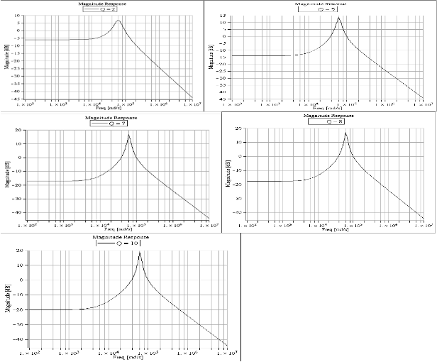
Fig.3: Sixth order active R-band pass filter at centre frequency fo = 10 kHz and Q= 2, 5, 7, 8, 10 respectively.
IJSER © 2014 http://www.ijser.org
International Journal of Scientific & Engineering Research, Volume 5, Issue 4, April-2014 1605
ISSN 2229-5518
![]()
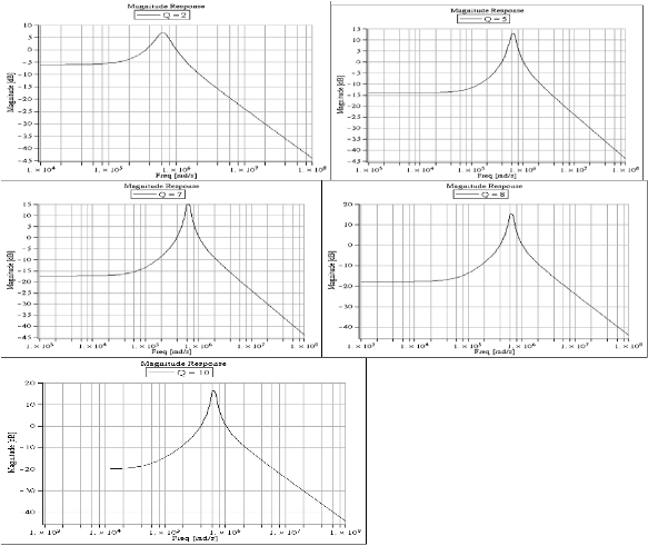
Fig. 4: Sixth order active R- band pass filter at centre frequency fo = 100 kHz and Q= 2, 5, 7, 8, 10
respectively
IJSER © 2014 http://www.ijser.org
International Journal of Scientific & Engineering Research, Volume 5, Issue 4, April-2014 1606
ISSN 2229-5518
Table 1 presents results for f0 = 10kHz, the pass band gain increases from a value of 6.71dB at Q=2 to 19.00 dB at Q=10. The bandwidth decreases from a value of
3629.24Hz to 1694.22Hz at Q=8 and Q=10. This implies good behavior of the filter at this centre frequency. Also the filter works and it has high selectivity which is in line with literature. Theory specifies that “increase in Q, leads to increase in the gain (G)” and “increase in Q yields a decrease in the bandwidth”. Also the increase in fo gives a decrease in the bandwidth. Furthermore, at a constant fo =100kHz, as presented in table 2,the pass band Gain is 6.73dB at Q=2 and increases to
16.18dB at Q=10, while the Bandwidth decreases from 40,107.05 Hz at Q=2 to
25,886.24 Hz at Q=10. This implies consistent behavior of the filter at this centre frequency. Also the filter really works and it has high selectivity which is in line with literature. In summary, the active R-band pass filter is characterized by high gain and narrow bandwidth at both f o= 10kHz and 100kHz.
CONCLUSION
It can be concluded from the above results that even though the constructed filter does not have same values as the simulated results, it still maintains the filter behaviour or characteristics. Therefore the filter
performs well at f0 = 10kHz and f0 = 100kHz up to a quality factor of Q=8. It is
IJSER © 2014 http://www.ijser.org
International Journal of Scientific & Engineering Research, Volume 5, Issue 4, April-2014 1607
ISSN 2229-5518
believed that there can be further improvement in the characteristics if more precise values of resistors and better operational amplifiers were used. This filter can also be used as a narrow band device because the selectivity is high, as well as to obtain high gains.
Carter, B(2001): Filter Design in thirty seconds. Texas Instrument Inc. Dallas.USA. Hashemi, K (2004): Filter design guide.
http/www.opamp,htm.Operational Amplifier Basics (01/11/2008).
Huelsman, L. P(1971): Equal Valued Capacitor Active-RC Network Realization of third Order Lowpass Butterworth Characteristic. Electron Lett.7: 291 – 293.
Hyong, K.K. and RA, J.B(1977): An Active Biguadratic Building Block without
External capacitors, IEEE Transactions on circuit and system, Vol. CAS-
24,No12.
Igwue, G. A(2007): Basic circuit theory and Industrial Electronics for Physicists.
Aboki Publishers, Makurdi. Nigeria.
Mesami, H(1992): Active–R Realisation of Current Mode Highpass
Filter.Int.J.Electronices,63: p. 335 -338.
IJSER © 2014 http://www.ijser.org
International Journal of Scientific & Engineering Research, Volume 5, Issue 4, April-2014 1608
ISSN 2229-5518
Prabhat, U. and Pal, K(2006): An Active Bandpass realization using Amplifier, Old city publishing inc.vol.1, p. 241 -245
Sergio, F(1998): Design with Operational Amplifiers and Analog Integrated Circuit, McGraw-Hill. New York, USA.
Shinde, G. N; Kadam, A. B; Kurumbatte, S. B and Patil, P.B(2002): Study of Active – R Second Order filter using feedback at Non-inverting terminal. Bulletin of pure and applied sciences vol.21D (1), p. 23 -31.
Shinde, G. N; Patil, P. B and Mirkute, P.R (2003): A third order active –R filter with feed forward input signal. Sadhana vol.28 (6) 1019 -1026.
Stark, P. A (2004): Band pass filters and Resonance.
Soderstand, M. A(1976): Design of Active –R Filter using only Resistance and
Operational Amplifier.Int.J.Electronics, Vol.(N0:8): p. 417 -437.
Soderstand, M. A and Mitra, S.K(1971): Sensitivity Analysis of Third Order –Filter
Int.J.Electron.30; p. 265 -273.
Srinivasan, S(1992): Synthesis of transfer function using the operation amplifier pole. Int. J. Electron.73; p. 1279–1283.
Wayne, S(2011): Active Band pass Filter, Electronics-Tutorials.ws. P.7-8
IJSER © 2014 http://www.ijser.org
International Journal of Scientific & Engineering Research, Volume 5, Issue 4, April-2014
ISSN 2229-5518
1609