International Journal of Scientific & Engineering Research Volume 2, Issue 5, May-2011 1
ISSN 2229-5518
Hybrid Mechanical Charger
Ayush R Jain, Chinmay V Harmalkar
Abstract— Mobile phone is our means to remain connected. While the phones have progressively got more powerful processors (clocking 1GHz), huge amounts of memory and large touch screen interfaces, their power requirement has increased correspondingly. Unfortunately, battery technology has not been growing at a comparable pace. Hence, there is a need to frequently charge the batteries. W hile travelling people face a common problem of charging electronic appliances like mobile, mp3 player, camera, etc. Solution to this problem is Hybrid Mechanical Charger, extracts energy from some reliable renewable source. Hence in order to achieve this, Hybrid Mechanical Charger uses mechanical energy from both windmill and hand crank. To compensate the difference in rpm a gear shifting mechanism is used.
Keywords— Gear box, Generator, Handcrank, W indmill
—————————— • ——————————
Existing battery chargers depend on the electricity supply. During travelling, avalibility of electricity supply is a problem. Hybrid Mechanical Charger is developed to solve this problem. Mechanical chargers have been pre- viously developed but they either have hand crank or windmill mechanism to provide mechanical energy to the generator. These Mechanical chargers are not reliable and hence they are not prevalent. Hybrid Mechanical Charger harnesses energy by both mechanisms - handcrank and windmill using a single generator. This is achieved by using gear shifting mechanism. Hybrid Mechanical Charger increases the relaiblity for charging of electronic appliances.
table 1)
TABLE 1
Gear Box Assembly
Generator is used to convert mechanical energy to elec- trical energy. Generator used is a permanent magnet geared dc motor. The stator consists of two magnets aligned with opposite poles facing each other and the rotor consists of three coils. When the shaft of the motor rotates, there is a relative motion between the permanent magnets and the coils which generates ac current in the coil. The flux associated with the coil is radial in nature. Commutator is used as a mechanical rectifier to convert AC current to DC current. The output of generator is 12v at 435rpm. The generator consists of a base motor and a gear box. The base motor rpm is quite large and to reduce the rpm it consists of a gear box. The gearbox consists of various gears such last gear is attached to the shaft. Gear
3 is mounted on gear 2 and gear 5 is mounted on gear 4. Gear 1 is attached to the shaft of the base motor. (Refer to
————————————————
Mechanical Enregy is required to produce electricity from generator, for which windmill and hand crank are used. The windmill has got three blades of length 117mm, which are attached to a hub of radius 23mm. Three blades are used to maintain proper rpm by reducing the effect of turbulence. It is a horizontal axis windmill which works on Bernoulli’s principle which says that “as the velocity of the fluid increases, the pressure exerted by that fluid de- creases”. The shape of the windmill blade is aerofoil which is the main cause of the lift force which drives the windmill. Linear velocity at every point on blade is dif- ferent because as radius changes at different point the linear velocity also changes.
v = rw (1)
v: linear velocity
r: Radius of windmill
w: Angular velocity
At the tip the linear velocity is maximum. Therefore the drag force at the tip will be maximum which will give rise to shearing force. It can cause damage to the blade. To reduce the shearing force the area of the tip is reduced by making the tip narrow.
The windmill rotates at 400-500 rpm which gives 9-10 V.
IJSER © 2011 http://www.ijser.org
International Journal of Scientific & Engineering Research Volume 2, Issue 5, May-2011 2
ISSN 2229-5518
The hand crank can be rotated with maximum of 120-150 rpm. When hand crank is used, the rpm of the shaft is reduced and generator provides less power. To increases the rpm of the generator, an additional spur gear of
40mm diameter is used which is mounted on another shaft. This additional gear will internally increase the rpm by 1:4 ratio because 40mm gear is connected to the final gear of the geanerator (10mm).
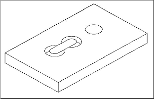
The Gearbox consists of two aluminum plates constitut- ing the top and the bottom surface. The bottom surface (fig 2) has got a hole for generator and two holes for fit- ting the bearing. The top surface (fig 1) has got a hole so that the shaft of the generator can come out and two holes for bearing. Both the surfaces have got a linear track so that the other shaft with 40mm gear can linearly move through it. Bearings are used to reduce friction and it also locks the shaft at proper position.
Fig 1. Top surface of the gearbox
TABLE 2
Motor Parameters
Motor Parameters | Symbol | Value |
Rated Motor Voltage | V | 12 v |
Current at rated voltage | I | 60mA |
Rated RPM | R | 435 |
Idle Current | Io | 22mA |
Internal Resistance | Ri | 11 Q |
Various motor parameters have been calculated and listed in table 2
Pi = VI (2) Pi : Input electrical power
Pi =0.72 W
Po = Pi – loss
Po : Output power
Loss includes both copper losses, mechanical loss which
includes losses due to friction and winding.
Copper loss will cause drop in voltage across the winding
of the motor which is denoted by Vcu.
Vcu = I Ri (3) Vcu = 0.66V
No load idle current Io is considered as the reason for me- chanical loss in motor.
Po = Pi – (V - Vcu) (I - Io) (4) Po = 0.43W
= Po /Pi (5)
: Efficiency of electric motor
= 60%
Kv = RPM / (V-Vcu) (6) Kv : RPM Constant
Kv = 38.36
max = 74%
max: Maximum Efficiency
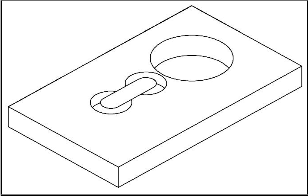
Fig 2. Bottom surface of the gearbox
600
400
200
0
0 5 10 15 20
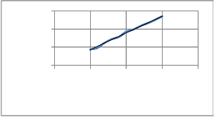
Fig 3. Voltage vs RPM characterictics
IJSER © 2011 http://www.ijser.org
International Journal of Scientific & Engineering Research Volume 2, Issue 5, May-2011 3
ISSN 2229-5518
Voltage is linearly related to the speed of rotations (rpm) as seen in fig 3.As the speed of rotation is increased more is the output voltage obtained. The black line shows the ideal characteristics.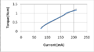
Fig 4. Current vs Torque characteristics
Torque and Current are linearly related to each other as seen in fig 4. The black line shows the ideal characteris- tics.
Standard Nokia mobile charger-
No load condition – Vout - 7.25V
Vout : Output voltage of the charger
With load (mobile connected for charging)- Vout - 4V
Iout - 200 - 300mA
Iout : Output current
Hybrid Mechanical Charger-
Minimum rpm required – 45
Vout – 3.9V
Iout - 150 - 250mA
Generator characteristics- Vgen -5.5V
Vgen : Output voltage of the generator
The existing generator is a radial flux motor which con- sists of a drum shaped base motor and a motor gearbox which occupies a lot of space. Axial Flux Generators are disc shaped flat and have got high power density, can accommodate more no of poles.These generator have
strong magnetic field due to neodymium-iron-boron magnets. The stator is made of thin coils or it is a printed circuited armature.
Worm wheel gear shifting arrangement will occupy very less space and gear shifting mechanism will become sim- ple. A worm gear will be mounted on the shaft of the Axial Flux Generator which will be in touch with 20mm worm wheel which will result in a gear ratio of 1:10. Vert- cical gear shift can be done which will consume very less space.
It can have a 1 Farad ultracapacitor which can store ener- gy in the form of charge. In emergency situations rather than using mechanical source of energy we can just dis- charge the capacitor and use the energy. 2500µFarads can provide energy of 1 rotation so 1 Farad can provide ener- gy for 400 rotations.
A Hybrid Mechanical Charger was successfully imple- meted on a Nokia phone. Charging of a mobile phone was done by both handcrank and windmill mechanism. It was found that the rate of charging from Hybrid Mechan- ical Charger is equivalent to the normal charger .
The authors wish to thank Mr. Dileep C. C, Mr. Anasta E.Rumao for their support and technical guidance.This work was supported in part by a grant from Fr. Concei- cao Rodrigues College of Engineering.
[1] B.L Theraja,A.K Theraja,” A Textbook of Electrical Technology” [2] Jacek F.Gieras, Rong-Jia Wang, Maarten J.Kamper, ”Axial Flux
Permanent Magnet Brushless Machines”
[3] Irving Gottlieb “Practical Electrical Motor Handbook” [4] David A Spera, ” Wind Turbine Technology”
[5] D.P Kothari, I.J Nagrath, ”Electric Machines ”
[6] J.R Davis, ” Gear Materials, properties and manufacture ” [7] D.A Neamen, “Electronic Circuit Analysis and Design”
IJSER © 2011 http://www.ijser.org