International Journal of Scientific & Engineering Research, Volume 4, Issue 9, September-2013 243
ISSN 2229-5518
Howrah Bridge and Second Hooghly Bridge: A Comprehensive Comparative Study
1Arnab Chakraborty, 2Ritaja Ray
Abstract: The Howrah Bridge and Second Hooghly Bridge has been serving the city of Kolkata in conjunction with each other by allowing the city to be well connected with the rest of the state and indeed the rest of the country. The bridges by themselves, the former being of balanced- cantilever form and the latter being cable-stayed, are marvels of bridge engineering with each being built in very different eras with tremendous variation in the technology that had been employed, all to serve the one purpose of improving communication and traffic conditions by releasing some of the volume exerted on each due to daily movement. The main issue of this research is to make a comparative review of the two bridges , mainly from strict technical points of views and also from the social and economic factors that arise out of them. The structural configurations, foundation characteristics, construction techniques and maintenance issues have been extensively discussed. Relevant statistical facts relating to traffic volume on the bridges and illustrations have been provided as and when required to verify some of the facts that has been discussed.
Keywords: balanced-cantilever, bridge engineering, cable-stayed, construction techniques, foundations, structural configurations, traffic volume
—————————— ——————————
1 INTRODUCTION
committee was appointed in 1855-56 by the then British
Government to oversee the possibilities of constructing a

The process of construction of the bridge was initially stalled due to the World War I, although the bridge was par-
bridge across the Hooghly River in the face of ever increasing
water traffic in the city of the then Calcutta (now Kolkata)
. However, it was only in 1868 that it was decided that a bridge
should be constructed and a newly allotted trust should be
vested with that responsibility. The Calcutta Port Trust was
thus created in 1870, and the Legislative department of the
then Government of Bengal passed the Howrah Bridge Act in
the year 1871 under the Bengal Act IX of 1871.
Eventually a contract was signed with Sir Bradford Le lie to construct a pontoon bridge, and work initiated, the different parts being constructed in England and sent to Calcutta to be assembled together. Despite suffering many hiccups and prob- lems along the way, the pontoon bridge was completed in
1874, at a total cost of  2.2 million, and opened to traffic on 17
October of that year. The bridge was then 465.7 m long and
18.9 ft. wide, with 2.14 m wide pavements on either side. In its
early days, the bridge was used to be periodically unfastened
to allow steamers and other marine vehicles to pass through.

Before 1906, the bridge was used to be undone for the passage
of vessels during daytime only, but since June of that year it
started opening at night for all vessels except ocean steamers,

which were required to pass through during day-
time. However the bridge started to prove inefficient to cater
————————————————
• 1Arnab Chakraborty (Corresponding Author), Graduate Engineer Trainee
(Civil), M.N. Dastur & Company (P) Ltd., Kolkata-700013, West Bengal
,INDIA, Ph: +91-9836360949, E-mail: arnab.besu.ces@gmail.com
• 2Ritaja Ray (Co-Author), Graduate Engineer Trainee (Civil), M.N. Dastur &
Company (P) Ltd., Kolkata-700013, West Bengal ,INDIA, Ph: +91-
9836564926, E-mail: ritaja.besu@gmail.com
• Both the authors are Graduates in Civil Engineering from Bengal Engineering
and Science University, Howrah-711103, West Bengal, INDIA

to the rapidly increasing load, and the Port Commissioners started making plans for a new improved bridge in 1905.
tially renewed in 1917 and 1927. In 1921, the 'Mukherjee
Committee', an elite group of engineers headed by Sir R.N.
Mukherjee, Sir Clement Hindley, Chairman of Calcutta Port
Trust and Mr. J. McGlashan, Chief Engineer, was formed. They
referred the matter to Sir Basil Mott, who proposed the con-
struction of a single span arch bridge. In 1922 the New How-
rah Bridge Commission was set up, to which the Mukherjee
Committee submitted its report. In 1926 the New Howrah
Bridge Act passed. In 1930 the Goode Committee was formed,
comprising Mr. S.W. Goode as President, Mr. S.N. Mallick, and
Mr. W.H. Thompson, to investigate and report on the advisa-
bility of constructing a pier bridge between Calcutta and How-
rah. Based on their recommendation, M/s. Rendel, Palmer and
Tritton were asked to consider the construction of a suspen-
sion bridge of a particular design prepared by their chief
draftsman Mr. Walton. On basis of the report, a global tender
was floated, and although the lowest bid came from a German
company, due to the imminent World War II and Germany's
possible participation in it, it wasn't given the contract, and
instead the British firm Cleveland Bridge & Engineering Com-
pany was entrusted with the bridge construction in 1935. The
same year the New Howrah Bridge Act was amended, and
construction of the bridge started the next year. When com-
missioned in 1943, it was the 3rd longest cantilever bridge in
the world. It has since been surpassed by three more bridges,
making it currently the sixth longest cantilever bridge in the
world.
Population and commercial activity grew rapidly after In-
dia gained independence in August 1947. The only link across
the Hooghly River at that time was the Howrah Bridge, which

was subject to much traffic congestion, with over 85,000 vehi-
cles every day, much higher than the design capacity. This
made it imperative that another bridge be built in order to
connect Kolkata with the other major cities of India via the
National Highways, which mostly emanated out of Howrah.
IJSER © 2013 http://www.ijser.org
International Journal of Scientific & Engineering Research, Volume 4, Issue 9, September-2013 244
ISSN 2229-5518
The foundation stone for the Second Hooghly Bridge, also known as Vidyasagar Setu, was laid on 20 May 1972. The bridge took more than 22 years to complete and cost Indian 
3.88 billion. Construction was actually stalled for seven years out of that 22 year period. Work on the cable-stayed bridge started with the construction of the well curb on the Calcutta bank end on 3 July 1979, and when commissioned on October
10, 1992, it became the longest span bridge of this type in the world. At that time it was the first cable-stayed bridge in India, the largest in Asia and the third largest in the world.
2 COMPARATIVE REVIEW
Together with the Howrah Bridge, the Second Hooghly Bridge vehemently increased connectivity of Kolkata with other parts of West Bengal and India. Road traffic became easier in many portions of the city leading to the improvement of economic and social factors. The bridge themselves provided employ- ment opportunities to a widespread percentage of population.
The two bridges, made to serve almost a similar purpose, are varied in a lot of respect. Constructional and architectural differences are huge, so are the nature and volume of traffic carried by each. The main aim of this research article is to point out the differences that exist within the structure and how it affects the purpose of construction in general and from the technical point of view, and finally make suitable comparisons between the two. The different aspects studied have been listed below in sequence.
2.1 Architectural Features
Technically, Howrah Bridge is a Suspension type Balanced Cantilever Bridge, with a central span 457.2 m between centers of main towers and a suspended span of 171.9 m. The main towers are 85.344 m high above the monoliths and 23.2 m apart at the top. The anchor arms are 99.1 m each, while the cantilever arms are 142.7 m each. The bridge deck hangs from panel points in the lower chord of the main trusses with 39 pairs of hangers.
The roads way beyond the towers are supported from ground, leaving the anchor arms free from deck load. The deck system includes cross girders suspended between the pairs of hangers by a pinned connection. Six rows of longitu- dinal stringer girders are arranged between cross girders. Floor beams are supported transversally on top of the string- ers, while they themselves supporting a continuous pressed steel troughing system surfaced with concrete. The longitudi- nal expansion and lateral sway movement of the deck are tak- en care of by expansion and articulation joints. There are two main expansion joints, one at each interface between the sus- pended span and the cantilever arms, and there are others at the towers and at the interface of the steel and concrete struc- tures at both approaches. There are total 8 articulation joints, 3 at each of the cantilever arms and 1 each in the suspended portion. These joints divide the bridge into segments with ver- tical pin connection between them to facilitate rotational movements of the deck. The bridge deck has longitudinal rul- ing gradient of 1 in 40 from either end, joined by a vertical

curve of radius 4000 ft. The cross gradient of deck is 1 in 48 between kerbs.
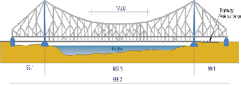
Figure 1. Schematic Elevation of Howrah Bridge


Vidyasagar Setu is a cable-stayed bridge, with 121 cables in a fan arrangement, built using steel pylons 127.62 metres (418.7 ft) high. With a total length of 823 metres (2,700 ft), Vidyasagar Setu is the longest cable–stayed bridge in India and one of the longest in Asia. The deck is made of com- posite steel-reinforced concrete with two carriageways. The total width of the bridge is 35 metres (115 ft), with 3 lanes in each direction and 1.2 metres (3 ft 11 in)-wide footpath on each side. The deck over the main span is 457.20 metres (1,500.0 ft) long. The two side spans are supported by parallel wire cables and are 182.88 metres (600.0 ft) long. Vidyasagar Setu is a toll bridge with free bicycle lanes. It has capacity to handle more than 85,000 vehicles in a day. The bridge was designed by Schlaich Bergermann & Partner, and checked by Freeman Fox & Partners and Bharat Bhari Udyog Nigam Limited. Con- struction was carried out by the consortium of Braithwaite, Burn and Jessop (BBJ). The Hooghly River Bridge Commission (HRBC) was responsible for the commissioning operations of the bridge.
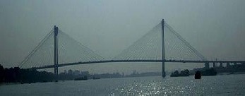
Figure 2. View of Second Hooghly Bridge, as seen from Howrah
Bridge.
2.2 Construction Technique

The Howrah Bridge does not have nuts and bolts, but was formed by riveting the whole structure. It required 26,500 tons of steel, out of which 23,000 tons of high-tensile alloy steel, known as Tiscrom, were supplied by Tata Steel. The main tower was constructed with single monolith caissons of di- mensions 55.31 x 24.8 m with 21 shafts, each 6.25 m2. The fab- rication was done by Braithwaite, Burn & Jessop Construction
IJSER © 2013 http://www.ijser.org
International Journal of Scientific & Engineering Research, Volume 4, Issue 9, September-2013 245
ISSN 2229-5518
Company at four different shops in Kolkata. The two anchor- age caissons were each 16.4 m by 8.2 m, with two wells 4.9 m square. The caissons were so designed that the working chambers within the shafts could be temporarily enclosed by steel diaphragms to allow work under compressed air if re- quired. The caisson at Kolkata side was set at 31.41 m and that at Howrah side at 26.53 m below ground level.

One night, during the process of grabbing out the dirt to enable the caisson to move, the ground below it gave way, and the entire mass subsided two feet, shaking the ground with an impact so intense that the seismograph a Kidderpore regis- tered it as an earthquake and a temple on the shore was de- stroyed, although it was subsequently rebuilt. While muck was being cleared, numerous varieties of objects were brought up, including anchors, grappling irons, cannons, cannon balls, brass vessels, and coins dating back to the East India Compa- ny.


The job of sinking the caissons was carried out 24 hours a day at a rate of a foot or more per day. The caissons were sunk through soft river deposits to stiff yellow clay 26.5 m below ground level. The accuracy of sinking the huge caissons was extremely precise, within 50–75 mm of the true position. After penetrating 2.1 m into clay, all shafts were plugged with concrete after individual dewatering, with some 5 m of backfilling in adjacent shafts. The main piers on the Howrah side were sunk by open wheel dredging, while those on the Kolkata side required compressed air to counter running sand. The air pressure maintained was about 40 lbs per square inch (2.8 bar), which required about 500 workers to be em- ployed. Whenever excessively soft soil was encountered, the shafts symmetrical to the caisson axes were left unexcavated to allow strict control. In very stiff clays, a large number of the internal wells were completely undercut, allowing the whole weight of the caisson to be carried by the outside skin fric- tion and the bearing under the external wall. Skin friction on the outside of the monolith walls was anticipated at
29 kN/m2 while loads on the cutting edge in clay overlying the
founding stratum reached 100 tons/m. The work on the foun-
dation was completed on November 1938.
By the end of 1940, the erection of the cantilevered arms
was commenced and was completed in mid-summer of 1941.
The two halves of the suspended span, each 282 feet (86 m)
long and weighing 2,000 tons were built in December 1941.
The bridge was erected by commencing at the two anchor
spans and advancing towards the center, with the use of
creeper cranes moving along the upper chord. 16 hydraulic
jacks, each of which had an 800-ton capacity, were pressed

into service to join the two halves of the suspended span.
The entire project cost 25 million (£2,463,887). The project
was a pioneer in bridge construction, particularly in India, but
the government did not have a formal opening of the bridge
due to fears of attacks by Japanese planes fighting the Allied
Powers. Japan had attacked the United States at Pearl Harbor
on December 7, 1941. The first vehicle to use the bridge was a
solitary tram.
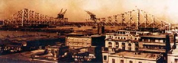
Figure 3. Howrah Bridge under construction.
The design of the Second Hooghly Bridge differs slightly from other bridges, which are of live load composite construc- tion. The difference is in the dead load design concept adopted for this bridge and concreting of the side spans done with support provided by the intermediate trestle. The deck is de- signed with a grid structure of girders. One set of girders are at the end and another set in the middle, which are braced by girders spaced on an average at 4.2 metres (14 ft) centre to cen- tre.
Deck erection cranes on trestle supports, designed for about 450 MT load of the deck grid, with heights varying from
24 m to 30 m, were used to erect the two side spans. The tres- tles were supported by raft foundations on the Calcutta side and on large diameter pile foundations on the Howrah side, which were on the river.
The structural steel used in the bridge weighs about 13,200 tonnes. The pylons, which are 128 metres (420 ft) in height, are designed as free standing portals. They are provided with two cross portal members, one at the bottom and another at the top, below the pylon head. The deck is connected to the end piers by bolts embedded in the chambers of the piers. Pylons made of 4×4m (13x13ft) steel boxes of riveted construction were raised on the two side spans of the bridge; one set is on the Calcutta side and the other is on the Howrah side. The six pylons on the Calcutta side of the bridge were installed using
75 MT and 50 MT cranes, while on the Howrah end, a single
50 MT crane was used. Anchorage of the pylon with the base
of piers was affected through Dywidag rods, duly anchored in
the piers.
Cables were erected from the four pylon heads with the
help of 32 MT hoist frames. The hoist frames were mounted on
top of each pylon. Sheave blocks, winches and snatch blocks
were used to facilitate the lifting, and cables inside the pylons
were stressed with jacks. Pressure grouting was performed to
fill the voids between the wire and the high-density polyeth-
ylene (HDPE) tubes. A two tonne tower crane, fixed inside the
pylons, lifted the cables into position. In order to stress the
cable inside pylon head, special jacks were imported from
Vermac, Bangkok together with pulling strand and
male/female strand sockets. The jacks were installed inside the
pylon heads at four locations with the help of a 2 MT capacity
tower crane fitted at pylon head.
The cables were manufactured at Usha Martin Industries,
Ranchi and transported to site via special low bed trailers
reeled in drums and then using the unreeling stand were un-
reeled at site over the approach deck. The cables were lifted by
the main hoist. To ensure the proper inclination of the cables at
IJSER © 2013 http://www.ijser.org
International Journal of Scientific & Engineering Research, Volume 4, Issue 9, September-2013 246
ISSN 2229-5518
deck and pylon head locations, the cables were guided by the saddle fixed both at the anchor points of main girders and pylon head.
The main span was erected from both sides as cantilever erection with the help of desk erection crane. The erecting ca- bles from the pylon head held the cantilever grid as the con- struction proceeded. Since the design was based on the phi- losophy of dead load composite, the concreting of the deck slab followed the four panels of steel work.
With the cantilever erection of the deck grid supported by cables, temporary bracings were erected for the lateral stability of the deck. The sequence of erection was repeated till the erection of panel 30 when it was necessary to hold deck piers 1 and 4 to prevent against uplift. To prevent that, four holding down cables in each cable plane, each cable tensioned at 555

MT to produce a vertical compression on the bearings, were provided at piers 1 and 4. Watering and dewatering of wells at piers 2 and 3 supporting the pylons were done in order to as- sess the settlement of the piers with the total load of the bridge.
Maurer Söhne expansion joints were provided to allow for
400 millimetres (16 in) horizontal expansion at the free
ends. Fixed end slab seal type expansion joints 115 millimetres
(4.5 in) were used for horizontal expansion of the joints. Other
essential components provided in the bridge structure are the
handrails, lightning arresters, crash barriers, gas service sup-
port structures, telephone and electric lines, lifts in the pylons,
and a maintenance gantry.
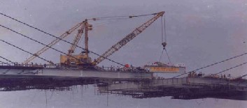
Figure 4. The mid-portion of the deck of the Second Hooghly Bridge being constructed, vividly showing some of the high capacity cranes used.
2.3 Traffic Volume

The Howrah Bridge serves as the gateway to Kolkata, con- necting it to the Howrah Station, which is one of the four in- tercity train stations serving Howrah and Kolkata. As such, it carries the near entirety of the traffic to and from the station, taking its average daily traffic close to nearly 1.5 million pe- destrians and 1 million vehicles. In 1946 a census was taken to take a count of the daily traffic, it amounted to 27,400 vehicles,
121,100 pedestrians and 2,997 cattle. The bulk of the vehicular traffic comes from buses and cars. Prior to 1993 the bridge used to carry trams also. From 1993 the tram services on the bridge were discontinued to curtail the increased load of vehi- cles on the bridge. However the bridge still continues to carry

much more than the expected load based on which it was de- signed and constructed. A 2007 report revealed that nearly
90,000 vehicles were plying on the bridge daily (15,000 of which were goods-carrying), though its load-bearing capacity is only 60,000. One of the main reasons of overloading was that although vehicles carrying up to 15 tonnes are allowed on the structure, vehicles with 12-18 wheels and carrying load up to 25 tonnes often plied on it. 31 May 2007 onwards, overload trucks were banned from plying on the bridge, and were redi- rected to the Vidyasagar Setu instead. The road is flanked by footpaths of width 15 feet, and they swarm with pedestrians.
The following traffic volume data charts show the flow of traffic on an average week day (8AM to 8 PM) along Howrah Bridge over the period of 40 years from 1959 to 1999.
Table 1. Share of various types of Fast-moving Heavy Vehicles along
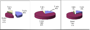
Howrah Bridge.
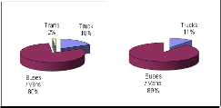
1959 1986 1990
1992 1999
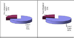
Table 2. Share of various types of Fast-moving Light Vehicles along
Howrah Bridge.
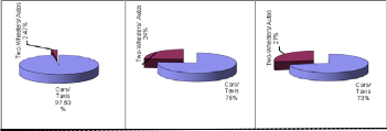
1959 1986 1990
IJSER © 2013 http://www.ijser.org
International Journal of Scientific & Engineering Research, Volume 4, Issue 9, September-2013 247
ISSN 2229-5518
1992 1999

Over the years, several accidents have occurred on the Se- cond Hooghly Bridge resulting in traffic congestion, and sometimes closure of the bridge for a few hours. To relieve the heavy traffic congestion at the entry to the bridge, the Hoogh- ly River Bridge Commissioners (HRBC) plan to build two one- way-exit and entry–ramps. These are planned with a semi- circular layout in the form of side wings, which will facilitate easy flow of traffic, before the toll plaza, on roads leading to the Howrah railway station. There are also plans to improve the lighting on the bridge by installing LED lamps and search lights covering the four pylons, the bridge spans, cables and under-deck. An electronic toll collection system is scheduled to be introduced by 2014, to help improve the flow of traffic across the bridge.
The traffic projections for the bridge at the planning stage have not been achieved. A traffic survey carried out for a week during June 2012 recorded traffic of 29,000 vehicles over the bridge in comparison to a projected 85,000. A survey conduct- ed during the same period in June 2012 indicated a figure of


31,865 vehicles, though it is reported by the concerned traffic and transportation engineer that the rate of increase in traffic has been one percent per year on the basis of traffic surveys carried out from time of commissioning of the bridge. The drop noticed that year could be because the survey was car- ried out at the height of monsoon and this can be a purely sea- sonal phenomenon. There could, however, be other reasons behind the drop in traffic. Also, the Vivekananda (Bally) Bridge too is in working condition, so the number of vehicles using Vidyasagar Setu may have come down. The survey has been conducted annually ever since the bridge was commis- sioned. It is usually done in winter, but in 2012, the depart- ment wanted to know the situation during the monsoon.
2.4 Maintenance Issues

The Kolkata Port Trust is the primary organization entrust- ed with the maintenance of the Howrah Bridge. The bridge has been subject to damage from vehicles due to rash driving, and corrosion due to atmospheric conditions and biological wastes throughout the years. On October 2008, 6 high-tech surveillance cameras were placed to monitor the entire 705- metre-long and 30-metre-wide structure from the control room. Two of the cameras were placed under the floor of the bridge to track the movement of barges, steamers and boats on the river, while the other four were fixed to the first layer of beams, one at each end and two in the middle, to monitor ve- hicle movements and potential human traffic. This was in re- tort to the extensive damage caused to the bridge from colli- sions with vehicles over the years, so that compensation could be claimed from the wrongdoers.
Corrosion, a major problem, has mainly been caused by bird droppings and human spitting. An investigation in 2003 revealed that as a result of prolonged chemical reaction caused by continuous collection of bird excreta, several joints and parts of the bridge were damaged. As an immediate measure,
the Kolkata Port Trust engaged contractors to regularly clean the bird droppings, at an annual expense of  500,000. In 2004, KPT spent
  6.5 million to paint the entirety of 2.2 million sq. m of the bridge. Two coats of Aluminium paint, with a primer of Zinc chromate before that, was applied on the bridge, re- quiring a total of 26,500 liters of paint.

Human spitting is another major factor for corrosion of the bridge. A technical inspection by Port Trust officials in 2011 revealed that spitting had reduced the thickness of the steel hoods protecting the pillars from six to less than three milli- meters since 2007. The hoods are of paramount importance the hangers need them at the base to prevent water seeping into the junction of the cross-girders and hangers, and damage to the hoods can jeopardize the safety of the bridge. Kolkata Port Trust announced that it will spend  2 million on covering the base of the steel pillars with fibre glass casing to prevent spit from corroding them.

On 24 June 2005, a private cargo vessel M V Mani, belong- ing to the Ganges Water Transport Pvt. Ltd, while trying to pass under the bridge during high tide, had its funnel stuck underneath for three hours, causing substantial damage worth about  15 million to the stringer and longitudinal girder of the bridge. Some of the 40 cross-girders were also broken. Two of four trolley guides, bolted and welded with the girders, were extensively damaged. Nearly 350 of 700 metres of the track were twisted beyond repair. The damage was so severe that KPT requested help from Rendall-Palmer & Tritton Limited, the original consultant on the bridge from UK. KPT also con- tacted SAIL to provide 'matching steel' used during its con- struction in 1943, for the repairs. For the repair costing around Rs5 million, about 8 tons of steel was used. The repairs were completed in early 2006.

The outer casing of the cables that hold Vidyasagar Setu together is in urgent requirement of maintenance after around two decades of bearing the load of heavy traffic, as a recent report has suggested. A team comprising specialists in differ- ent fields such as cables, bearings and bridge structure recent- ly submitted its report to the Hooghly River Bridge Commis- sioners (HRBC), an autonomous body responsible for the showpiece structure’s upkeep.

HRBC had commissioned the report after an internal re- view revealed that maintenance work conducted could be bet- ter than what had previously being taking place. There had been some problems in the absence of a detailed, long-term maintenance manual. So a team was formed to look into properly maintaining the bridge which included representa- tives from the Civil Engineering Department of Bengal Engi- neering and Science University, officials of Consulting Engi- neering Services, and a bearing manufacturing company.
HRBC has fallen back on Schlaich Bergermann & Partner, the German company that designed Vidyasagar Setu, to sug- gest a maintenance plan based on the technical report sent to its Stuttgart headquarters. Experts said the condition of the outer casing of the cables was crucial to maintaining the stabil- ity of the bridge. Those used in the bridge are all specially made steel cables and each lies embedded in anti-corrosive
IJSER © 2013 http://www.ijser.org
International Journal of Scientific & Engineering Research, Volume 4, Issue 9, September-2013 248
ISSN 2229-5518
material. An outer casing of high-density polyethylene pipes ensures the cables are not exposed to the elements.
Sources said some of the cables’ outer casing had devel- oped cracks because of natural wear and tear and exposure to sun and rain. There have also been sporadic incidents of trucks hitting the base of the cable anchorage. As has so far been the case, it has been mostly patchwork repairs such as welding the parts of the pier close to the base of the deck slab, where they remain anchored. The top section has largely re- mained unattended, as claimed by senior officials of the inves- tigative teams.

The inspection report probed into the maintenance of spe- cific parts of the bridge, including the girders, pier caps, ex- pansion joints, decks, crash barriers and drainage, which men- tions that some of the bearings need to be replaced. The un- derbelly of some of the deck slabs on the approach to the bridge need repairs too.
3 CONCLUSION
Thus, to conclude this theoretical discussion, we can obviously state the importance these two bridges hold in lieu of the city of Kolkata and its surrounding areas. They are of paramount importance for the city to function efficiently as communica- tion itself is a cornerstone on which Kolkata and Howrah are based. They add beauty to the Kolkata skyline and attract huge number of tourists to the city which keeps it ticking from an economic and commercial point of view. Thus it is really necessary to understand the requirements of these bridges and maintain their viability to serve the population of the region.


Structurally, both are marvels and are epitomes of unique- ness in architecture and design. The volume of construction work that needed to be done to erect these monumental struc- tures is worth studying and was great engineering challenges for the builders. The engineering study of Howrah Bridge and Second Hooghly Bridge thus provide ground for engineers to go on and build similar types of structures all over the world. Though balanced-cantilever bridges are generally not built these days due to the huge amount of material and time re- quirement, it still is worth studying from the durability con- cept of bridges and provides areas where maintenance tech- niques can be developed. On the other hand, Second Hooghly Bridge is relatively modern in terms of the design considera- tions. The materials required were lot lesser than the Howrah Bridge and hence is an ideal example for other cities to build bridges to cater for huge amount of vehicular population.
Thus, if we see from all these different aspects, it is worth studying about these bridges in intricate details, an earnest
and petite example being this discussion.
4 REFERENCES
[1] Gunguly, C. K.; Battarcharya, S. K., "The Design Methodology and Construction Technique of 457 m Span Cable Stayed Bridge (Dead Load Composite) at Vidyasagar Setu", Cable Stayed, Supported And Suspension Bridges, Indian Institute of Bridge Engineers, pp. 113-114,
2000.
[2] Krishna Raju, N., Design of Bridges (Fourth Edition), Tata McGraw-Hill, pp-438, 2007
[3] Johnson Victor, D., Essentials of Bridge Engineering (Fifth Edition), Ox- ford & IBH Publishing Co. Pvt. Ltd., New Delhi, 2001
[4] Virola, J., The World’s Greatest Bridges, Proceedings of the American
Society of Civil Engineers, Vol. 38, No. 10, Oct. 1968, pp. 52-55
[5] Chatterjee, A. K. & Dharap, V. M., Problems of construction of caisson foundations of the Second Hooghly Bridge (Vidyasagar Setu) at Calcutta and their solutions, presented at Foundations for major bridges, IABSE Col- loquium, New Delhi, India, 1999.
[6] Gupta, S. P., “The Second Hooghly River Bridge, Calcutta”, Structural
Engineering International, August 1991, n. 3 v. 1
[7] Rao, S. & Tippur Narayanarao, Pylon foundations of four cable stay bridg- es, presented at Foundations for major bridges, IABSE Colloquium, New Delhi, India 1999.
[8] Leonhardt, F., Bridges (4th Edition), Deutsche Verlags-Anstalt, Stuttgart, Germany, ISBN 3421025908, 1994, pp.-173
[9] Brown, David J., Bridges, Macmillan Publishing Company, New York, USA, ISBN 002517455X, 1993, pp. 92-93
[10] Basu, K., “Maintenance call for Stability of Setu”, The Times of India, Thursday Edition, March 7, 2013, http://www.telegraphindia.com/1130307/jsp/calcutta/story_16643259.js p#.Uevm2dIweDN
[11]”Vidyasagar Setu/ Second Hooghly Bridge”, Wikipedia, http://en.wikipedia.org/wiki/Vidyasagar_Setu
[12]”Howrah Bridge/ Rabindra Setu”, Wikipedia, http://en.wikipedia.org/wiki/Howrah_Bridge
IJSER © 2013 http://www.ijser.org