International Journal of Scientific & Engineering Research, Volume 3, Issue 10, October-2012 1
ISSN 2229-5518
Helianthus – a Low Cost High Efficient Solar
Tracking System Using AVR Microcontroller
Arindam Bose, Sounak Sarkar, Sayan Das
Abstract — A solar tracking system is a generic term used to describe devices that orient various payloads toward the sun. Payloads can be photovoltaic panels, reflectors, lenses or other optical devices. This paper describes a potential solar system using two stepper motors, light sensor and a concave mirror. This method not only improves power collection efficiency by about 65% by developing a sys tem that tracks the sun to keep the solar panel at perpendicular to its rays but also decreases the overall cost of production. This solar tracking system is designed, practically implemented and experimentally tested. The design details and the experimental results are shown.
Index Terms — ATMEGA16 (AVR Family) Microcontroller, Concave Mirror, Darlington Pair Transistor, LDR Sensor, Power Optimization, Renewable Energy, Tracking system.
1 INTRODUCTION
—————————— ——————————
HE alternative power source is continuously achieving greater popularity especially since the realisation of fossil fuel’s shortcomings. Sources such as Solar, Wind, Hydro
and Geothermal have all been utilised with varying levels of success. Solar energy is less popular than other forms of re- newable energy due to the relatively high cost of solar cells and their low conversion efficiency. It is necessary to recover as much energy as possible from a solar power system because in an average only 15-20% of total incident energy can be con- verted into usable electrical energy. This low conversion ratio reduces again due to light gathering losses. Light gathering is dependent on the angle of incidence of the light source to the solar cell’s surface. The closer is the panel to perpendicular, the greater is the power. If a flat solar panel is mounted paral- lel to ground, the sunlight will have an incident angle close to
90° in the morning and the evening. At such an angle, the
light gathering ability of the cell is essentially zero. As the day
progresses to midday, the angle of incidence approaches 0°,
causing a steady increase in power until at the point where the
light incident on the panel is completely perpendicular, and
maximum power is achieved. As the day continues toward dusk the increasing angle causes the power to decrease again
toward minimum. Maximizing power output from a solar system is desirable to increase efficiency. In order to maximize power output from the solar panels, one needs to keep the panels aligned with the sun. As such, a means of tracking the sun is required. This can be achieved by tilting the solar panel to continuously face the sun. This process of sensing and fol- lowing the position of the sun is known as Solar Tracking.
————————————————
Arindam Bose is currently pursuing B.Tech degree in electronics and communication engineering from Future Institute of Engineering and Management of West Bengal University of technology, India, PH-
+919051320505. E-mail: adambose1990@gmail.com. His area of interests includes pure mathematics and electronics.
Sounak Sarkar is currently pursuing B.Tech degree in electronics and communication engineering from Future Institute of Engineering and Management of West Bengal University of technology, India, PH-
+919051389590. E-mail: sounak19@gmail.com.
Sayan Das is currently pursuing B.Tech degree in electronics and commu-
nication engineering from Future Institute of Engineering and Manage-
ment of West Bengal University of technology, India, PH-+918420550471.
E-mail: sayandas1990@gmail.com.
This is a far more cost effective solution than purchasing addi- tional solar panels. It has been estimated that the yield from solar panels can be increased by 30 to 70 per cent by utilizing a tracking system instead of a stationary array. This project de- velops an automatic tracking system which will keep the solar panels aligned with the sun in order to maximize efficiency in a very efficient manner.
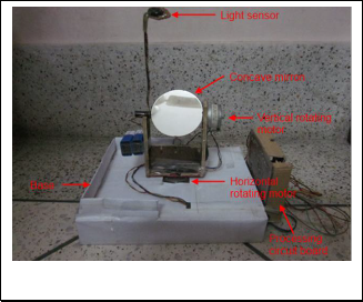
Fig. 1 Picture of Helianthus - the Solar Tracker.
Fig. 1 shows our design module which is named as ‘Helian- thus’. Helianthus is the Greek name of sunflower. In our de- sign simple Light Dependent Resistor (LDR) is used as light sensor along with a simple theory of optics. That makes it a low cost intelligent device compared with other solar tracking system. More over in standard tracking system the solar cell itself is used as the tracking media, which incorporates a con- troller system installed along with it. Thus every solar device needs a controller system for its own purpose. But in our de- sign, a single tracker module can feed a number of solar de- vices in parallel, thus minimizing the extra amount of energy loss as well as cost of production.
IJSER © 2012
http://www.ijser.org
International Journal of Scientific & Engineering Research Volume 3, Issue 10, October -2012 2
ISSN 2229-5518
2 TRACKING PRINCIPLE
Many different methods have been proposed and used to track the position of the sun. The simplest of all uses an LDR – a Light Dependent Resistor to detect light intensity changes on the surface of the resistor. The proper and efficient use of LDR with a concave mirror reduces the overall cost as well. The resistivity of LDR decreases significantly with increasing illu- mination. Fig. 2 shows the general resistivity vs. illumination plot of an LDR.

3 BLOCK REPRESENTATION
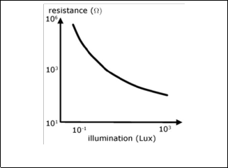
Fig. 4 Block Diagram of Helianthus.
Fig. 2 Resistivity vs. illumination plot of an LDR.
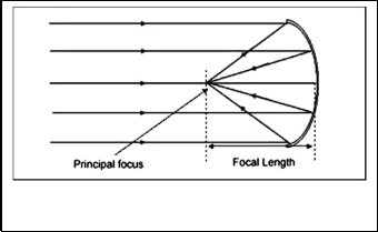
The efficiency of LDR increases with directed rays. Concen- trated and directed incident light rays can be achieved by us- ing concave mirrors. When parallel rays incident on concave mirror, they reflected back and converge in the focal plane. If the incident parallel rays are essentially perpendicular to the focal plane, they meet at the principal focus. This phenomenon is used in this design. The LDR is kept at the principal focus. The solar rays are assumed to be parallel to each other as the source (i.e. the sun) is at about infinite (essentially large) dis- tance from the mirror. So they are expected to be converging into the principal focus when they are perpendicular to the focal plane as shown in Fig.3. So if we scan the total upper hemisphere i.e. the day-sky, at some single point only, the so- lar rays are expected to incident on the principal focus i.e. de- tected by the LDR, in other positions, they will meet at focal plane and are not detected by the LDR sensor. Thus the accu- rate position of the sun can be tracked.
The description of the each block in Fig.4 is given following.
3.1 Power supply
This device needs +5V/500mA DC power supply for the mi- crocontroller section and +12V DC/1A power supply for the motors.
3.2 Controlling section: Microcontroller
The Microcontroller is the main controlling part of the whole system. It controls the whole tracking by following certain algorithm.
3.3 Input section: LDR sensor
This is the main input section where the analog level of volt- age is collected by the microcontroller’s Analog to Digital con- verter (ADC) for further processing.
3.4 Output section: Motor driver
Motor driver circuit is used for driving the stepper motors. There are two separate drivers for driving two separate step- per motors.
3.5 Motor unit
There are two motor units. One for movement of base (hori- zontal movement) and other for movement of the concave mirror (vertical movement).
3.6 Indication
These are simple Light Emitting Diodes (LEDs). The red LED indicates the power supply. The yellow LED glows when total calculation is being carried on by the MCU. When calculation is over, the system stabilizes in the direction of the Sun and the green LED glows.
Fig. 3 Parallel sunrays converge to the focus after reflecting from the concave mirror.
IJSER © 2012
http://www.ijser.org
International Journal of Scientific & Engineering Research Volume 3, Issue 10, October -2012 3
ISSN 2229-5518
4 STRUCTURAL DESCRIPTION OF THE DEVICE
to the amount of light intensity directed towards it. It is con- nected in series with resistor.
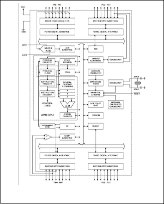
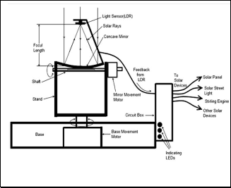
Fig. 5 Structural Diagram of Helianthus.
Fig. 5 shows the structural diagram of our design. There are two stepper motors used for movement for two degrees of freedom (horizontal and vertical). The vertical motor is re- sponsible for movement of the concave mirror and the hori- zontal motor is used for movement of the stand or base. A photo sensor (LDR) is placed at the principal focus of the con- cave mirror. From the light sensor a feedback signal is sent to the microcontroller for defining how much steps the motors should rotate according to an algorithm. The microcontroller is also giving feedback signal to all connected solar devices to align towards the sun. In the connected solar devices there is an arrangement similar to the tracking system except the con- troller section. Only two motors are installed in the solar de- vices for movement in horizontal and vertical direction respec- tively. Detailed description is as follows:
4.1 Power supply
The AC mains (220-250V) voltage is stepped down by the cen- ter tap transformer (15-0-15), rectified by bridge rectifier and finally filtered out by capacitors to obtain a steady DC level. Then it is passed to a +5 volt DC regulator (IC7805) and +12 volt DC regulator (IC7812) to obtain a +12 volt DC output.
4.2 Microcontroller
The Microcontroller we have used here is ATMEGA16 which belongs to ATMEL AVR microcontroller family. Detailed pro- gramming is written here. The ATmega16 is a 40 pin low- power CMOS 8-bit microcontroller based on the AVR en- hanced RISC architecture. The Atmega16 has three key fea- tures that satisfy our objective. These are as follows: 512 Bytes EEPROM, 32 Programmable I/O Lines, inbuilt 10 bit 8 channel Analog-to-Digital converter. The block diagram of ATmega16 is shown in Fig.6.
4.3 LDR sensor module
This is the light sensor which senses the intensity of sunlight. The sun tracker system designed here uses the Cadmium Sul- phide (CdS) photocell for sensing the light. This photocell is a passive component whose resistance is inversely proportional
Fig. 6 Block Diagram of ATmega16.
4.4 Stepper motor driver
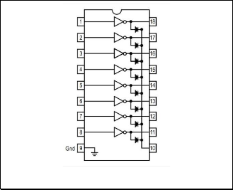
Motor driver circuit is used for driving the stepper motors. We have used here IC ULN2803. The eight NPN Darlington con- nected transistors in this family of arrays are ideally suited for interfacing between low logic level digital circuitry (such as TTL, CMOS or PMOS/NMOS). It is an 18-pin octal high volt- age high current Darlington Pair array with voltage rating 50V and current rating 500mA. Fig.7 describes internal structure of ULN2803.
Fig. 7 Internal structure of ULN2803.
IJSER © 2012
http://www.ijser.org
International Journal of Scientific & Engineering Research Volume 3, Issue 10, October -2012 4
ISSN 2229-5518
4.5 Stepper motor unit
There are two unipolar stepper motor units. One is for move- ment of base and other is for movement of the concave mirror.
4.6 Concave mirror
A Concave mirror is a mirror with a curved reflective surface, most curved mirrors have surfaces that are shaped like part of a sphere, but other shapes are sometimes used in optical de- vices. The sun tracker uses here a concave mirror of 15 cm fo- cal length.
5 WORKING PROCEDURE
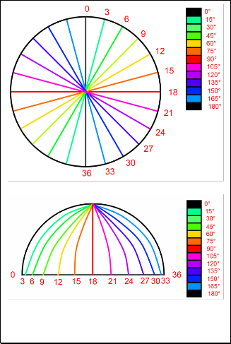
This Solar tracker is basically dual axis tracker. At first it will scan all the values of light intensity in each point of the upper hemisphere where the sun actually lies. The stepping angle of both the stepper motors used here is 5 degree per step. Both the motor will rotate 180 degree covering all the points in the upper hemisphere, thus rotating 180/5 i.e. 36 times each. Fig. 8 shows the various rotational positions of two motors in differ- ent angles. This scanning process will take 1-2 minutes de- pending on the stepper motor and program logic.
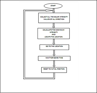
the LDR sensor is located. The resistance of LDR will change according to the light intensities. So the voltage drop across the LDR will also be changed. This voltage drop is fed to an ADC, and hence corresponding digital values are stored in the microcontroller memory in the form of a 36x36 matrix. After scanning is completed, it will check all the intensity values and decide which one is the maximum and hence the corre- sponding co-ordinates are located which is in turn the position of the sun. Then it will move to the calculated co-ordinates, as well as it will also send the direction information to move ac- cording to that position to all the solar devices connected to it where the movement arrangement is also present. It will wait for some time, until a noticeable change in the position of the sun occurs and then after returning to its initial position, it will start scanning again and thus the solar devices will direct to- wards next location of the sun. Hence maximum amount of energy is obtained. More over this gives a nearly constant amount power. The waiting time can be changed by the pro- gram written in the microcontroller. Fig. 9 describes the algo- rithm of the whole process.
(a)
Fig. 9 Algorithm of tracking system.
6 HARDWARE DESIGN
(b)
Fig. 8.(a) Horizontal rotational positions (top view) and (b) Verti- cal rotational positions (side view) of stepper motor.
While scanning, when the mirror will be directed towards the sun, parallel sunrays (as they are coming from infinite source) will incident on it, and converge into the focus where
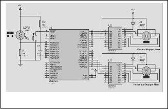
Fig. 10 Circuit Diagram of solar tracking system.
IJSER © 2012
http://www.ijser.org
International Journal of Scientific & Engineering Research Volume 3, Issue 10, October -2012 5
ISSN 2229-5518
Fig.10 is the schematic of the solar tracking system. The Micro- controller ATmega16 has been used as the brain of the project. It is connected to the necessary connections as depicted in the Fig.7. Two separate ULN2803 ICs have been used as the step- per motor driver with necessary connections. PA0/ADC0 (pin
40) is used as the Analog input from the LDR. PC0-PC3 (pin
22-25) and PD4-PD7 (pin 18-21) are connected to the horizon-
tal and vertical motor drivers respectively. Other necessary
connection is done in the microcontroller IC such as VCC,
GND, AVCC, AREF etc. The microcontroller is running by
8MHz internal clock. Other pins are connected to the indicat-
ing LEDs. Fig 11 shows the front and back side of actual circuit
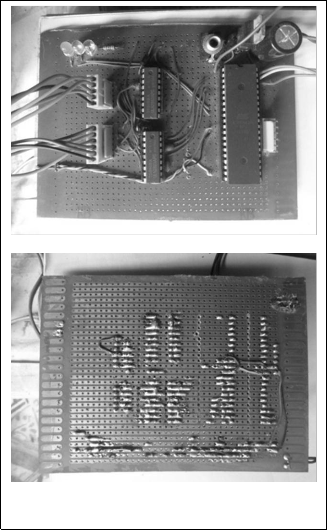
of the project design.
system is called as ‘Static Panel System’ and the later one is named as ‘Helianthus Tracking System’. Both the sections were continued from 06:00 AM to 06:00 under the clear sky in the month of April in almost same experimental environment. In both the sections the output was connected to a resistive load that would dissipate 6W. 6W-12V corresponds to a cur- rent of 500mA, so by Ohm’s law; a load resistance was calcu- lated as 24Ω. But a 22Ω resistor was the nearest value found and was connected to the solar panel. The voltage across the load and current through the same were taken using two sep- arate multimeters, and were recorded every half-hour time span. The experimental results are shown in Table 1 and a rel- ative comparison in terms of average power, standard devia- tion and variance is shown in Table 2.
(a)
TABLE 1
NET OUTPUT POWER FROM STATIC PANEL SYSTEM AND HELIAN- THUS TRACKING SYSTEM IN VARIOUS TIME OF THE DAY
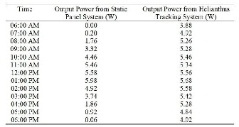
W = watt
TABLE 2
AVERAGE OUTPUT POWER, THEIR STANDARD DEVIATION AND VAR- IANCE OF STATIC PANEL SYSTEM AND HELIANTHUS TRACKING SYSTEM
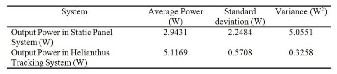
W = watt
(b)
Fig. 11.(a) Front side and (b) Back side of the actual circuit.
7 CALCULATIONS OF POWER EFFICIENCY
The experimental setup in our laboratory comprised of a solar tracking module connected with a 6W-12V solar panel made of polycrystalline silicon. The experiment had two sections: In the first section we measured the net output power from the solar panel without incorporating the solar tracking system, keeping it in a flat orientation and in the next section the ex- periment went with the Helianthus tracking system. The first
The experimental results show various aspects of Helian- thus tracking system. In conventional static panel system there is a certain time period when the maximum amount of energy can be generated in only where the position of the sun is per- pendicular to the panel plane. This happens once in 24 hrs. for few minutes. Whereas in solar panels with tracking system, the panel plane is perpendicular to the position of the sun al- most every time, so that average net power output is much higher. However in the later type the maximum amount of power is less than the output power rating of the solar panel as a small amount of energy is required to run the tracking system. We measured the total amount of power generated in
12 hrs. by both the systems from the graph in Fig.14. Accord-
IJSER © 2012
http://www.ijser.org
International Journal of Scientific & Engineering Research Volume 3, Issue 10, October -2012 6
ISSN 2229-5518
ing to the areas under the curves, the total amount of output power generated by a standard static panel system is 37.73W in 12 hrs. and 62.57W in case of Helianthus Tracking System in the same span of time. That means we can generate 65% more energy from the solar panel while using with the Helianthus module. More over the tracking system does not consume en- ergy at a constant rate all the time. It consumes a small amount of energy only when it scans the location of the sun and rest of the time it remains idle. Again as depicted in Table
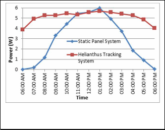
2 we can generate a nearly constant level of output power as the standard deviation and variance of the net output power in Helianthus system is much lower than that of a standard static panel system.
Fig. 14 Experimental results showing the comparison between a solar panel with and without tracking system
7 DISCUSSIONS
The Helianthus Solar Tracker was proposed, designed and con- structed. In terms of real value, the overall cost of a system can be reduced significantly, considering that much more power can be supplied by the solar array coupled to a solar tracking device. By extracting more power from the same solar panel, the cost per watt is decreased, thereby rendering solar power much more cost-effective than previously achieved using fixed solar panels. The Helianthus Solar Tracking System has many applications. The system can be utilized for tracking the sun and thus pointing the solar panel at the point of maximum solar intensity. It can also be employed with Stirling engine by more efficient use of concen- trated heat energy. We can use this in some home appliance like solar water heater or something like that. A single experimental module setup costs as low as US$25-$30 (in the year of 2011) whereas many commercial units cost in excess of US$2000 for a unit that can track the sun while bearing a panel of considerable weight. The experimental results show that it is highly energy efficient. More accurate design can enhance solar power genera- tion rate by 75-80% after consuming a small amount of electrical power. Thus this low cost and energy efficient solar tracking sys- tem can be used in various industrial and domestic purposes. This could be a subject for further development. Solar tracking is by far the easiest method to increase overall efficiency of a solar power system for use by domestic or commercial users.
8 CONCLUSION
This project has presented a means of controlling a sun track- ing array with an embedded microcontroller system. Specifi- cally, it demonstrates a working software solution for maxim- izing solar cell output by positioning a solar array at the point of maximum light intensity. This project utilizes a dual-axis design versus a single-axis to increase tracking accuracy. The electronics needed to activate the motors are simple and the system can be applied to any electromechanical configuration. With minor adjustments it can be used with various types of collectors including flat-plate, compound parabolic, evacuated tube, parabolic trough, Fresnel lens, parabolic dish and helio- stat field collectors.
ACKNOWLEDGMENT
We acknowledge with thanks our college Future Institute of Engineering and management for encouraging and advising us.
REFERENCES
[1] “Solar devices and solar tracking system,”
http://en.wikipedia.org/wiki/Solar_tracker. 2011
[2] “Concave mirrors,” http://en.wikipedia.org/wiki/Curved_mirror.
2011
[3] “LDR sensors,” http://en.wikipedia.org/wiki/Photoresistor. 2011
[4] “Stepper Motors,” http://en.wikipedia.org/wiki/Stepper_motor.
2011
[5] C. F. Gay, J. H. Wilson and J. W. Yerkes, “Performance advantages of two-axis tracking for large flat-plate photovoltaic energy systems,” Conf. Rec. IEEE Photovoltaic Spec, 1982.
[6] N. Barsoum and P. Vasant, “Simplified Solar Tracking Prototype”,
Transaction in Controllers and Energy, ISSN: 1985-9406 Online Pub- lication, ES-E11/GJTO, June 2010.
[7] Z. Xinhong, W. Zongxian and Y. Zhengda, “Intelligent Solar Track- ing Control System Implemented on an FPGA”, Nios II Embedded Processor Design Contest—Outstanding Designs 2007.
[8] E. Anderson, C. Dohan, A. Sikora, “Solar Panel Peak Power Tracking
System”, Worcester Polytechnic Institute, March, 2003.
[9] 8-bit AVR Microcontroller with 16K Bytes In-System Programmable Flash ATmega16, ATmega16L, Technical Datasheet, Atmel Corpora- tion, 2006.
[10] Octal High Voltage, High Current Darlington Arrays ULN2803, ULN2804, Technical Datasheet, Motorola, Inc. 1996.
[11] LM 78XX Series Voltage Regulators, Technical Datasheet, National
Semiconductor Corporation, May 2000.
IJSER © 2012
http://www.ijser.org