International Journal of Scientific & Engineering Research Volume 2, Issue 10, October-2011 1
ISSN 2229-5518
Harmonic Analysis of 6-pulse Converter in DTC Induction Drives using UPQC
R.KAMESWARA RAO, G.RAVI KUMAR, and S.S.TULASI RAM
Abstract— In this paper the control technique that used is direct torque control technique. This one is suitable and favourable among the available controls because it is less sensitive to the motor parameters, minimal torque response time, absence of controllers such as PID for motor flux and torque. Along with DTC it is necessary to have an inverter in order to control the torque and speed by means of varying the inverter states. A six Pulse AC-DC Converter provides dc supply to the inverter. Here it involves harmonics in supply currents due to this six pulse rectifier. In this paper a simulink model of DTC with an induction motor has been designed and implemented for six pulse converters. It involves harmonics in supply currents due to this six pulse rectifier. To minimize the harmonics on six pulse converter in DTC Induction motor drive using three phase Unified Power Quality Conditioner (UPQC) is used. The Dynamic model of the UPQC is developed in the MATLAB/SIMULINK environment and the simulation results demonstrating the power quality improvement in the system are presented through FFT analysis.
Index Terms— Direct Torque Control, Unified Power Quality Conditioner, Harmonics, High-Power Drives, Multi-pulse Converters, Power
Quality.
—————————— ——————————
HIS torque control of induction motors was developed and presented by I. Takahashi as direct torque control (DTC) [1],[2]. The complete block diagram of motor drive is shown in the Fig. 1. The Controlled electrical drives are made up of several parts: the electrical machine, the power conver-
ter, the control equipment and the mechanical load.
Fig.1. Complete block diagram of Induction motor drive
----------------------------------
Author: R.Kameswara Rao, Associate professor, Electrical and Electronics Engineering Department, Jntu College of Engineering, Kakinada, Andhra Pra- desh, India. e-mail id: rkameswara@gmail.com.
Co-Author: G.Ravi Kumar, Associate professor, Electrical and Electronics Engineering Department, Bapatla Engineering College, Bapatla, Andhra Pra- desh, India. e-mail id: goli.ravikumar@yahoo.com
Co-Author: Dr. S.S.Tulasi Ram, Professor, Electrical and Electronics Engi- neering Department, Jntu College of Engineering, Kakinada, Andhra Pradesh, India. e-mail id: ramsankara@gmail.com
Direct Torque Control (DTC) [3] has emerged over the last decade to become one possible alternative to the well- known Vector Control of Induction Machines.
Its main characteristic is the good performance, obtaining results as good as the classical vector control but with several advantages based on its simpler structure and control diagram. In DTC it is possible to control directly the stator flux and the torque by se le ct in g t h e a ppro pr i a t e in v e rt e r st a t e . Th e loads based on power electronic devices generally pollute the nearby network by drawing non sinusoidal cur- rents from the source.
The rapid switching of electronic devices creates additional Problems. This makes voltages and currents at the point of common coupling (PCC) highly distorted [4]. One of the best solution to compensate both current and voltage related prob- lems, simultaneously, is the use of Unified Power Quality Conditioner (UPQC) [5].One of the electrical system adapter structures is back to back inverter. According to the control- ling structure, back to back inverters might have different op- erations in compensation. For example, they can operate as shunt and series active filters to simultaneously compensate the load current, harmonics and voltage isolation. This is achieved by so called UPQC.
In Direct Torque Control it is possible to control directly the stator flux and the torque by selecting the appropriate inverter state. The electromagnetic torque in the three phase induction machines can be expressed as follows
IJSER © 2011
International Journal of Scientific & Engineering Research Volume 2, Issue 10, October-2011 2
ISSN 2229-5518
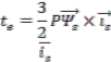
(1)
Where ![]() is the stator flux, is the stator current (both fixed to the stationary reference frame fixed to the stator) and P the number of pairs of poles. The previous equation can be mod- ified and expressed as follows:
is the stator flux, is the stator current (both fixed to the stationary reference frame fixed to the stator) and P the number of pairs of poles. The previous equation can be mod- ified and expressed as follows:![]() (2) Where
(2) Where ![]() is the stator flux angle and
is the stator flux angle and ![]() is the stator current
is the stator current
one, both referred to the horizontal axis of the stationary frame
ing state. Thus the stator flux linkage move in space in the
direction of the stator voltage space vector at a speed that is proportional to the magnitude of the stator voltage space vec- tor. By selecting step by step the appropriate stator voltage vector, it is then possible to change the stator flux in the re- quired way. If an increase of the torque is required then the torque is controlled by applying voltage vectors that advance the flux linkage space vector in the direction of rotation. If a decrease in torque is required then zero switching vector is applied, the zero vector that minimize inverter switching is selected.
In summary if the stator flux vector lies in the kth sector and the motor is running anticlockwise, torque can be increased
fixed to the stator. If the stator flux modulus is kept constant
by applying stator voltage vectors V
k+1
or V
k+2
, and decreased![]()
and the angle is changed quickly, then the electromagnetic
by applying a zero voltage vector V0
or V7. The Decoupled
torque is directly controlled. The same conclusion can be ob-
tained using another expression for the electromagnetic tor- que.
![]() (3) Because of the rotor time constant is larger than the stator one,
(3) Because of the rotor time constant is larger than the stator one,
the rotor flux changes slowly compared to the stator flux; in
fact, the rotor flux can be assumed constant. The fact that the rotor flux can be assumed constant is true as long as the re- sponse time of the control is much faster than the rotor time constant. As long as the stator flux modulus is kept constant, then the electromagnetic torque can be rapidly changed and controlled by means of changing the angle (ρs - ρr.)
![]()
The way to impose the required stator flux is by means of choosing the most suitable Voltage Source Inverter state. If the ohmic drops are neglected for simplicity, then the stator vol- tage impresses directly the stator flux in accordance with the following equation:
(4)
control of the torque and stator flux is achieved by acting on
the radial and tangential components of the stator voltage space vector in the same directions and thus can be controlled by the appropriate inverter switching. In general, if the stator flux linkage vector lies in the kth sector, its magnitude can be increased by using switching vectors Vk-1 (for clockwise rota- tion) or Vk+1 (for anticlockwise rotation), and can be decreased by applying voltage vectors Vk-2 (for clockwise rotation) or Vk+2 (for anticlockwise rotation). It can be seen from table.1 that the
states Vk and Vk+3 , are not considered in the torque because
they can both increase (first 30 degrees) or decrease (second 30 degrees) the torque at the same sector depending on the stator flux position. The usage of these states for controlling the tor- que is considered as one of the aims to develop in the present paper by dividing the total locus into twelve sectors instead of just six.
TABLE 1
GENERAL SELECTION TABLE FOR DIRECT TORQUE CONTROL, BEING "K" THE SECTOR NUMBER
Or
![]() (5)
(5)
Decoupled control of the stator flux modulus and torque is achieved by acting on the radial and tangential components respectively of the stator flux-linkage space vector in its locus. These two components are directly proportional to the com- ponents of the same voltage space vector in the same direc- tions. From Eq. 4 it can be seen that when the inverter voltage directly forces the stator flux, the required stator flux locus will be obtained by choosing the appropriate inverter switch-
In Fig. 2 a possible schematic diagram of Direct Torque Con- trol [6] is shown. As it can be seen, there are two different loops corresponding to the magnitudes of the stator flux and torque. The reference values for the flux stator modulus and the torque are compared with the actual values and the result- ing error values are fed into the two level and three-level hys- teresis blocks respectively. The position of the stator flux is divided into six different sectors. The stator flux modulus and torque errors tend to be restricted within its respective hyste-
IJSER © 2011
International Journal of Scientific & Engineering Research Volume 2, Issue 10, October-2011 3
ISSN 2229-5518
resis bands. It can be proved that the flux hysteresis band af- fects basically to the stator-current distortion in terms of low order harmonics and the torque hysteresis band affects the switching frequency. The DTC requires the flux and torque estimations which can be performed as it is proposed in Fig. 3 schematic, by means of two different phase currents and the state of the inverter.
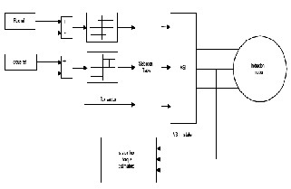
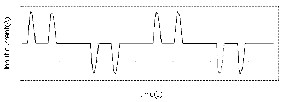
Fig.4. Output voltage of the 6-pulse rectifier
(a)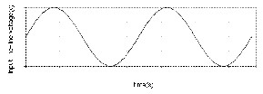
Fig. 2. Direct Torque Control schematic diagram
However flux and torque estimations can be performed using
other magnitudes such as two stator currents and the mechan- ical speed or two stator currents again and the shaft position.
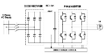
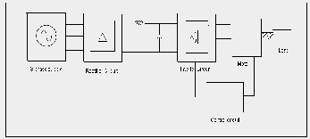
The half-wave rectifier in the three-phase case also yields DC components in the source current. The source has to be large enough to handle this. Therefore it is not advisable to use three-phase half-wave rectifier topology for large power ap- plications. The three-phase half-wave rectifier employs three diodes while the full-wave H-bridge configuration employs six diodes. 6-pulse rectifier [7] as shown in the Fig. 4. In this configuration there are 6 uncontrolled devices i.e. diodes feed- ing to the intermediate circuit, inverter circuit and induction motor.
Fig.3. Six pulse rectifier with motor drive
The output voltage wave forms of the above 6-pulse rectifier is shown in the Fig. 4
(b)
Fig.5. (a) input current of the 6-pulse rectifier (b) input L-L voltage of
the 6-pulse rectifier
The wave forms of the input supply current and voltages are shown in the Fig. 5. The current waveform at the inputs of a rectifier is not continuous. The voltage waveform at the input of the rectifier is continuous.
A harmonic is a component of a periodic wave having a fre- quency that is an integral multiple of the fundamental power line frequency. The total harmonic distortion is the contribu- tion of all the harmonic frequency currents to the fundamen- tal. The order of current harmonics produced by a semicon- ductor converter during normal operation is called as charac- teristic harmonics. In a three-phase, six-pulse rectifier with out DC bus capacitor, the characteristic harmonics are nontriplen odd harmonics (e.g., 5th, 7th, 11th, etc.). In general the charac- teristic harmonics generated by a semiconductor rectifier are given by: h =kq ± 1.Where h is the order of harmonics; k is any integer, and q is the pulse number of the semiconductor rec- tifier (six for a six-pulse rectifier).
The pulsed discontinuous waveform observed commonly at the input of a three-phase full-wave rectifier system depends
IJSER © 2011
International Journal of Scientific & Engineering Research Volume 2, Issue 10, October-2011 4
ISSN 2229-5518
greatly on the impedance of the power system, the size of the DC bus capacitors, and the level of loading of the DC bus ca- pacitors.
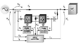
Fig.6. General Model of UPQC
In addition to this, loads are becoming very sensitive to vol-
tage supplied to them. The loads based on power electronic devices generally pollute the nearby network by drawing non sinusoidal currents from the source. The rapid switching of electronic devices creates additional Problems. This makes voltages and currents at the point of common coupling (PCC) highly distorted [8]. One of the best solution to compensate both current and voltage related problems simultaneously, is the use of Unified Power Quality Conditioner (UPQC) [9]. One of the electrical system adapter structures is back to back in- verter.
According to the controlling structure, back to back inverters might have different operations in compensation. For exam- ple, they can operate as shunt and series active filters to simul- taneously compensate the load current, harmonics and voltage isolation. This is called UPQC. In order to clear the switching oscillation; a passive filter is applied to the output of each in- verter. At the output of shunt inverter, high pass second order LC or first order RC filter is allocated and at the output of se- ries inverter, low pass second order LC or resonance filter is allocated. The UPQC controller provides the compensation voltage through the UPQC series inverter and provides condi- tioning current through the shunt inverter by instantaneous sampling of load current and source voltage. The control strat- egy is basically the way to generate reference signals for both shunt and series APFs of UPQC.
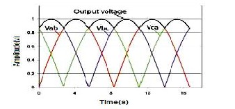
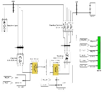
To verify the performance of the UPQC, a 6 Pulse converter with DTC Induction drive is connected as shown in Fig. 7 and Fig. 8.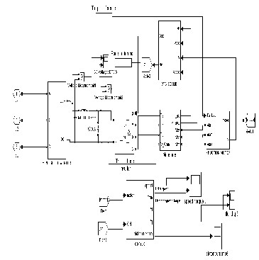
Fig. 7. UPQC Controlled six pulse converter with DTC Induction Drive
Fig.8. Six pulse converter with DTC Induction Drive
Simulation results of UPQC controlled six pulse converters with DTC Induction drive are presented in Fig. 9 and Fig. 10 and comparative total harmonic distortion analysis of voltage and current are shown in Tables 2 and 3 respectively.
IJSER © 2011
International Journal of Scientific & Engineering Research Volume 2, Issue 10, October-2011 5
ISSN 2229-5518
(a)
(b)
(c)
(d)
Fig.9. FFT current Harmonic analysis (a) without Control device (b) With
Shunt Active Filter (c) With Series Active Filter (d) With UPQC
(a)
(b)
(c)
(d)
IJSER © 2011
International Journal of Scientific & Engineering Research Volume 2, Issue 10, October-2011 6
ISSN 2229-5518
Fig.10. FFT Voltage Harmonic analysis (a) without Control device (b) With
Shunt Active Filter
(c) With Series Active Filter (d) With UPQC
TABLE 2
THE PERCENTAGE OF TOTAL HARMONIC DISTORTION ANALYSIS OF VOLTAGE
Phase | Voltage | |||
Without UPQC | Shunt APF | Series APF | UPQC | |
A | 33.96 | 31.92 | 17.68 | 15.95 |
B | 41.2 | 39.11 | 21.09 | 21.03 |
C | 37.54 | 36.67 | 20.80 | 20.92 |
TABLE 3
THE PERCENTAGE TOTAL HARMONIC DISTORTION ANALYSIS OF CURRENT
Phase | Current | |||
Without UPQC | Shunt APF | Series APF | UPQC | |
A | 13.7 | 12.75 | 11.36 | 11.16 |
B | 22.29 | 20.09 | 19.89 | 17.01 |
C | 28.11 | 27.34 | 27.27 | 26.98 |
The drive drives a load according to the requirements based on their parameters. Here the used drive is induction motor drive which matches it’s load and speed to the given reference load, torque and speed values. The matching of these refer- ence values to the output values of the drive is mainly depend on the control technique used in the drives. Here in our paper the direct torque control (DTC) technique is used and for mi- nimizing harmonics unified power quality conditioner is used. A Matlab / Simulink based simulation carried out in order to
verify its performance. The simulation results indicate that the series compensator isolates the source voltage harmonics and the current harmonics are isolated by shunt compensator for Loads. As seen from the above analysis the total voltage har- monic distortion and the total current harmonic distortion are reduced considerably by using UPQC.
REFERENCES
[1] Takahashi, I.;, Noguchi.T. (1986): A new quick-response and high- efficiency control strategy of an induction motor. IEEE Trans. Ind. Appl., vol IA-22, No 5.
[2] Takahashi; Ohmori, Y. (1989): High-performance direct torque con- trol of an induction motor. IEEE Trans. Ind. Applicat., vol. 25, pp.
257–264.
[3] Domenico Casadei; Francesco Profumo; Giovanni Serra: FOC and DTC: Two Viable Schemes for Induction Motors Torque Control. IEEE Transactions on Power Electronics, Vol. 17, No. 5, September
2002, pp. 779-787.
[4] JenoPaul, Ruban Deva Prakash, Jacob Raglend (2010): Design and Simulation of Phase Locked Loop Controller Based Three Phase Uni- fied Power Quality Conditioner for Nonlinear and Voltage Sensitive loads. International journal of applied Engineering research, Dindi- gul, Vol.1, No.2.
[5] Bhim Singh; Venkateswarlu. P. (2010): A Simplified Control Algo-
rithm for Three Phase, FourWire Unified Power Quality Conditioner. Journal of Power Electronics, Vol.10, No. 1, pp 91-96.
[6] Direct Torque Control for Induction Motors Based on Discrete Space Vector Modulation. International Journal of Applied Engineering Re- search, ISSN 0973-4562 Volume 2, Number 3 (2007), pp. 453–466.
[7] Chaturvedi, P. K.; Shailender Jain. (2006): Multi pulse converters as a viable solution for power quality improvement. IEEE.
[8] The control techniques drives and control hand book V.Khadkikar, A. Chandra, O.Berry and T.D.Nguyen, 2006, “Conceptual study of Unified Power Quality Conditioner (UPQC)”. IEEE ISIE, July 912.
[9] A. Elnady, and M.M.A. Salama, (2001): New functionalities of an adaptive unified power quality conditioner. in Proc. IEEEPES Winter Meeting’01,pp 295 300.
R. Kameswara Rao received B.Tech and M.Tech degrees in Electrical En- gineering from JNTU College of Engineering, Kakinada. He is presently working as Associate professor in Electrical and Electronics Engineering department in the same college. His areas of interest include Power quali- ty and Harmonics analysis.
G.RaviKumar graduated from Andhra University College of Engineering, Visakhapatnam, India and received M.Tech from JNTU College of Engi- neering, Kakinada. He is currently working as Associate professor in EEE Department at Bapatla Engineering College, Bapatla, India. His areas of interest are Power System operation and Control, Power System Protec- tion.
IJSER © 2011
International Journal of Scientific & Engineering Research Volume2, Issue 10, October-2011 7
ISSN 2229-5518
Dr.S.S.Tulasi Ram received B.Tech, M.Tech and Ph.D degrees in Electrical Engineering from JNTU College of Engineering, Kakinada. He is currently working as professor of Electrical and Electronics Engineering in the same college. His areas of interest include high voltage engineering, Power system analysis and control.
IJSER © 2011
http //www 11ser org