prevents excessive current to be drawn from the motors which can damage the Arduino and gives a regulated 9
Volts supply to the DC motors.
International Journal of Scientific & Engineering Research, Volume 5, Issue 9, September-2014 616
ISSN 2229-5518
Varun Varadan, Antara Sharma, Dhruvin Sheth, Aakash Shroff
Abstract:- W e use a simple concept of using hand gestures to control a bot. The bot is controlled wirelessly using radio frequency receivers and transmitters. W e also use an Arduino Software to program the accelerometer so that it can move according to the hand gestures. Additionally, a motor driver is used as an interface between Arduino and robot motors to limit the current flowing through the motors. The end result of this is pretty accurate according to what is set in the program. The bot can move forward ,backward ,left and right by mere hand gestures.
Index Terms— Accelerometer, hand gestures, wireless, RF module.
—————————— ——————————
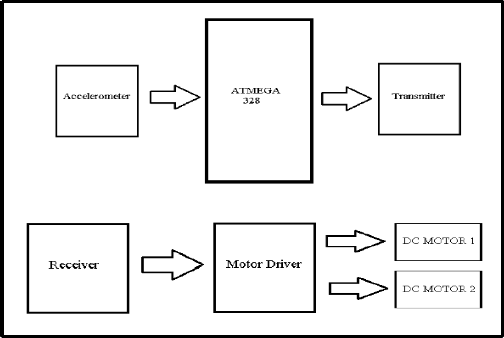
The paper theorizes the use of an accelerometer which has
3 axes X, Y and Z which allows us to move the output device (robot in our case) to move in those respective directions. The code for movement is uploaded on the Arduino board and the accelerometer is connected at the Arduino pins. Further, TX is connected
to the Arduino board through which data is transmitted wirelessly and received by the RX which is connected with the motor driver to the robot. The motor driver circuit
prevents excessive current to be drawn from the motors which can damage the Arduino and gives a regulated 9
Volts supply to the DC motors.
The components needed are:
Fig 1: Block Diagram
1. Encoder(HT12E)
2. Decoder(HT12D)
3. Tx and Rx pair(RF Module)
IJSER © 2014 http://www.ijser.org
International Journal of Scientific & Engineering Research, Volume 5, Issue 9, September-2014 617
ISSN 2229-5518
4. LED lamps(5 nos)
5. Reset switched(4 nos)
6. Bread board
7. Power supply
We first connect the power supply to the encoder and decoder as per the data sheets. We will then design the
encoder part using resistors and reset switches. LEDs are used to show reception of data at data output lines, ie they will glow when data is received. These LEDs are then connected to the decoder separately. The encoder-decoder configuration is shown below: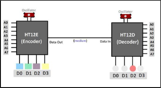
Fig 2: Encoder-Decoder connection
For simplicity, a direct link is shown above. Actually we use an RF module to transmit and receive.
IJSER © 2014 http://www.ijser.org
International Journal of Scientific & Engineering Research, Volume 5, Issue 9, September-2014 618
ISSN 2229-5518
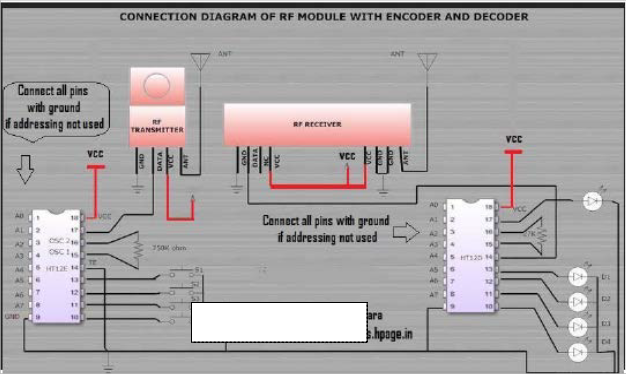
Fig 3: System design
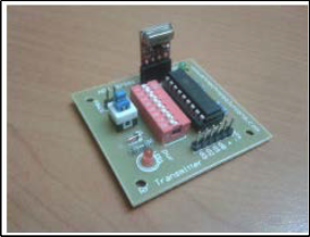
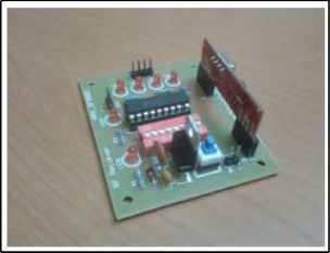
Fig 4: RF Transmitter module Fig 5: RF receiver module
IJSER © 2014 http://www.ijser.org
International Journal of Scientific & Engineering Research, Volume 5, Issue 9, September-2014 619
ISSN 2229-5518
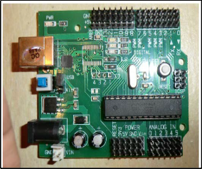
Fig 6 : Arduino
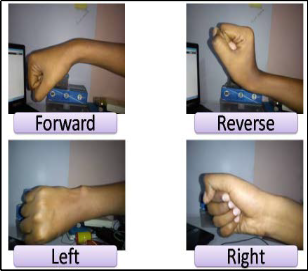
Fig 7 : Hand Movements
The project is based on hand movements, and therefore the accelerometer must be placed in your hand. The palm should turn as shown in the figures, in order to move in a particular direction. As the palm turns, the accelerometer moves which causes changes in the accelaration due to gravity. This change is expressed in terms of analog voltage. The signal is then given to a trasnmitter. The transmitting device includes a comparator IC for analog to digital conversion and an encoder IC (HT12E) which is
used to encode the data which is then transmitted by the RF
transmitter module.
At the receiving end, the RF receiver module receives the
encoded data and decodes it using a decoder IC (HT12D).
This data is then processed by the arduino and then finally by the motor driver, to control the motors.
void setup() //Function to define input and output pins
{ Serial.begin(9600); Serial.println("start");
pinMode(A0,INPUT); //Input pins to arduino from
accelerometer
pinMode(A1,INPUT);
pinMode(13,OUTPUT); //Output pins from arduino
pinMode(12,OUTPUT); pinMode(11,OUTPUT); pinMode(10,OUTPUT);
}
void loop() //The statements in function void loop() is
executed in a loop
{
int a=analogRead(A0); int b=analogRead(A1);
if(a>400 && a<600) //forward movement
{
digitalWrite(10,HIGH); digitalWrite(11,LOW); digitalWrite(12,HIGH); digitalWrite(13,LOW); delay(1000);
}
else if(b<600 && b>400) //right movement
{ digitalWrite(10,HIGH); digitalWrite(11,LOW); digitalWrite(12,LOW); digitalWrite(13,LOW); delay(1000);
}
else if(a<300 && a>100) //backward movement
{ digitalWrite(10,LOW); digitalWrite(11,HIGH); digitalWrite(12,LOW); digitalWrite(13,HIGH); delay(1000);
}
else if(b<300 && b>100) //left movement
{
digitalWrite(10,LOW);
digitalWrite(11,LOW); digitalWrite(12,HIGH); digitalWrite(13,LOW); delay(1000);
}
else //stop movement
IJSER © 2014 http://www.ijser.org
International Journal of Scientific & Engineering Research, Volume 5, Issue 9, September-2014 620
ISSN 2229-5518
{
digitalWrite(10,LOW);
digitalWrite(11,LOW); digitalWrite(12,LOW); digitalWrite(13,LOW); delay(1000);
}
}
With advancements in technology it is always more convenient to do work using gestures instead of manually doing it..Further wireless controls add to the power of having to do work sitting at one place without moving and manually going to the object. It has also aided the Medical field with an important application called as Accelerometer Based Hand Gesture Controlled Wheelchair
Costly affair as accelerometer and wireless components like RX and TX modules are expensive.. Further accelerometers are sensitive and slight changes can affect the sensitivity and cause the accelerometer to stop responding desirably..
Vibrations are an important part of the world around us, from our ears' ability to use them to hear sounds and unwanted noise, to earthquakes which cause low- frequency, destructive, vibrations. Being able to measure them is very useful for many things, including geophysics, and is often done using an accelerometer.
Wheelchairs are used by the people who cannot walk due to physiological or physical illness, injury or any disability. Recent development promises a wide scope in developing smart wheelchairs. The present article presents a gesture based wheelchair which controls the wheelchair using hand movements. The system is divided into two main units: Mems Sensor and wheelchair control. The Mems sensor, which is connected to hand, is an 3-axis accelerometer with digital output (I2C) that provides hand gesture detection, converts it into the 6- bit digital values and gives it to the PIC controller. The wheelchair control unit is a wireless
unit that is developed using other controller.
We created a wearable game controller that uses accelerometers to acquire action of the hand and then maps an action to an arbitrary keystroke. The types of actions we are trying to recognize should be suitable as input control for video games.
We placed 3 z-axis accelerometers on tips of the thumb, the index finger and the middle finger, and three accelerometers on the back of the hand for x, y, and z acceleration. The Atmega644 microcontroller read the output of the accelerometers and simulates a finite state machine to compute the gesture and the motion of the hand. The gesture and motion information is then transmitted to PC through serial connection, and a Java program is used to read the information and map it to an arbitrary keystroke.
IJSER © 2014 http://www.ijser.org