International Journal of Scientific & Engineering Research, Volume 2, Issue 11, November-2011 1
ISSN 2229-5518
GSM based Multi node Pressure Sensor in
Barometric Altimeter – A Survey
K. Immanuvel Arokia James, K. Sudheer
Abstract--- Our proposed project was mainly based on GSM networks and controller. Barometer is a well-organized tool for determining atmospheric pressure. The altimeter is a tool which calculates the vertical distance in accordance with a reference level. The barometric altimeter, computes the altitude according to the atmospheric pressure. Accuracy and size are the major issues in altimetry. MEMS based Barometric Altimeter is implemented using the following two terminals of embedded barometer Module. Even though the size of the MEMS based Barometric Altimeter is reduced, it provides more accuracy. The measured parameters are transmitted through commands using GSM modem from the controller to the mobile network. In the other end the GSM data is received and the readings are compared and the corresponding adjustments are made by the controller by vertical wheel adjustments. This process will be continued to achieve the equal level. This methodology can be used to measure the altitude at different places by means of separate arrangement.
Index Terms— GSM, MEMS, Barometeric altimeter.
—————————— ——————————
I. INTRODUCTION
LTIMETER is used to calculate the altitude of an object over a predetermined level. The altimeter is
an apparatus which determines vertical distance in ac- cordance with a reference level. Louis Paul Cailletet was the French physicist who invented the altimeter and the high-pressure manometer. The conventional altimeter established in the majority of aircraft executes its work by calculating the air pressure from a stationary port. Air pressure reduces with the raise of altitude - about one millibar ( inches of mercury) per
  feet (
 m) closer to sea level. The altimeter is consistent to provide the pressure straightforwardly as altitudes, suitable to a mathematical model defined by the International Stan- dard Atmosphere (ISA).

Barometer is a well-organized tool for computing at- mospheric pressure. It was invented in 1643 by the Italian scientist Evangelista Torricelli, who utilized a column of water in a tube ft (
ft ( ) long. This difficult water column was almost immediately substituted by mercury, which is denser than water and requires a tube about ft ( m) length.
————————————————
K. IMMANUVEL AROKIA JAMES is pursuing PhD in VEL TECH Dr. RR
& Dr. SR Technical University, Chennai, India. He is currently working as Assistant Professor cum Head of the Department of EEE at VEL Tech Multi Tech Dr. RR Dr. SR Engineering College.
Email: immanuel_james@yahoo.com
K. Sudheer received his B.E from GKCE, Sullurpet in 2008 and M.E degree from Veltech, Anna University in 2010. He is currently working as a Assistant Professor in Electrical and Electronics Engineering at VEL Tech Multi Tech Dr.RR and Dr.SR Engineering College, Chennai.
Email: sudheerk_115@inbox.com
The mercurial barometer contains a glass tube, sealed at one end and loaded with unadulterated mercury. After being heated to force out the air, it is overturned in a little cup of mercury called the cistern. The mercury in the tube goes under the surface to some amount, producing above it a vacuum (the Torricellian vacuum).
The barometric altimeters perform its work by compu- ting air pressure and comparing it to a particular altitude. At elevated altitudes, air pressure reduces; at small alti- tudes, air pressure raises. A barometric altimeter com- putes the air pressure identical to a meteorological baro- meter and then converts that measurement into an amount of altitude. A barometric altimeter has to be stan- dardized for adjustments to local air pressure to achieve a good exact reading.
Accuracy and size are the major concern in altimetry. On the other hand the current day altimeter makes use of tradtional pressure sensors which consumes more floor space and offers very poor accuracy. To resolve this issue, in this paper implemented a Micro Electro Mechanical System (MEMS) based pressure sensor in the design of barometric altimeter.
II. MICRO ELECTRO MECHANICAL SYSTEMS
Micro Electro Mechanical Systems (MEMS) are little in- tegrated apparatus or arrangement that integrates elec- trical and mechanical elements. They vary in size from the sub micrometer altitude to the millimeter altitude and there can be several numbers, from a small number to millions, in a specific system. MEMS broaden the fabrica- tion approaches developed for the integrated circuit in-
IJSER © 2011
http://www.ijser.org
International Journal of Scientific & Engineering Research, Volume 2, Issue 11, November-2011 2
ISSN 2229-5518
dustry to include mechanical elements for instance
beams, gears, diaphragms and springs to devices.
These devices can sense, manage and trigger the me- chanical processes on the micro scale, and perform inde- pendently or in arrays to produce effects on the macro scale. The micro fabrication machinery facilitates fabrica- tion of huge arrays of apparatuses, which independently carry out simple tasks, but in combination can carry out complicated functions.
was developed in order to interface the system with the
real time environment. Investigating the memory space required and the resolution of the ADC unit 8051 was chosen to be the MCU for the reference design. A sophis- ticated Human Machine Interface (HMI) was also created by using mode selection switches as the input device and a LCD unit, Stepper motor with wheel alignment and GSM modem are the output devices.
2.1 MEMS BASED PRESSURE SENSOR
The use of MEMS technology has created a break- through in the design of sensors. Extremely small silicon capacitive absolute pressure sensor can now be realized by utilizing the MEMS technology. This new break through has created possibilities to design extremely ro-
Barometer
Sensor
Display
Instrumentation
Amplifier
Controller
Unit
A
D Stepper
C
Motor
bust capacitive pressure sensing elements with low cur-
rent consumption and excellent performance.
The complete sensor component is only 6mm in diame- ter and 1.7mm high. This device is capable of detecting the smallest barometric pressure change, which enables extremely accurate weather forecasting and altitude mea- surements. The supply voltage ranges from (3-5) V and current consumption of (0.5-50) µA make it easy to inte- grate into products like sport watches and other equip- ments.
III. GSM - MEMS ALTIMETRY
3.1. Design Criterion
1. The barometric altimeter system needs a pressure sen- sor that must have a pressure range of 64kPa to 105 kPa.
2. There are three different kinds of pressure measure- ments: gauge, absolute and differential. As the most important objective is to calculate alterations in am- bient pressure, hence there is requirement for a known pressure reference. As a result, the pressure sensor must be able to measuring absolute pressure.
3. Since there can be huge temperature transform from one elevation to another, the sensor for the design should be reference calibrated and temperature ba- lanced.
4. Therefore a 1-bar, compensated, MEMS based abso- lute pressure sensor would be the best choice that would design the design criterion.
3.2. Working
A real time working model of a MEMS based ba-
rometric altimeter was created as per the design. After the design and selection of an appropriate pressure sensing element and amplification circuit an embedded circuitry
Wheel Ar- rangement
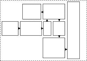
Fig-1: Block Diagram of Single node
Pressure and temperature are the two physical quantities that are necessary to calculate the value of alti- tude from the reference plane (Mean Sea Level).The value of atmospheric pressure prevailing in the environment is sensed by the pressure sensors whereas the ambient tem- perature is sensed by using an appropriate temperature sensor.
The analog signals from these sensors are fed in- to the inbuilt ADC of the microcontroller. The digital val- ues thus obtained are processed according to the mathe- matical model which correlates the values of pressure with altitude. Hence from the known values of pressure and temperature the values of unknown variable, ’Alti- tude’ can be found out.
As an attempt for effective data utilization the values of sensed temperature and pressure are also dis- played in the LCD along with the calculated value of alti- tude. A sophisticated Human Machine Interface (HMI) is created by using three mode selection switches which enables the user to use the equipment in three different operating modes.
3.3. Embedded barometer Module
The working model of the MEMS based altimeter com- prises of two terminals
The terminals are made for the accommodation of the MEMS sensor, vacuum gauge and an exhaust valve. A low pressure region is created by sucking out air from the
IJSER © 2011
http://www.ijser.org
International Journal of Scientific & Engineering Research, Volume 2, Issue 11, November-2011 3

ISSN 2229-5518
sealed chamber using a vacuum pump. The low pressure
region thus formed is maintained by closing the needle valve.
The embedded module comprises of the electronic components required for the sensing and processing of
Wheel align- ment with ver- tical track
The height adjustments are made by the controller by vertical wheel alignments. This process will be continued to achieve the equal level.
the two physical quantities i.e., temperature and pressure.
3.4. Modes of Operation
The reference design of the MEMS based altimetry is mainly concerned towards the accurate measurement of altitude. In the process of determining the altitude two of the physical parameters i.e. pressure and temperature are processed. Therefore as an attempt of effective data utili- zation, these values of atmospheric pressure and ambient temperature are displayed.
In order to display the real time values a HMI is created using press button switches which makes the sys- tem to operate in three different modes.
In mode one the system operates as an altimeter and it provides the altitude values in meters. In mode two the system operates in barometric mode and it provides the value of atmospheric pressure in terms of torr. Whereas in mode three the system is designed to operate as a tem- perature sensor and it display the ambient temperature in degree Celsius. The modes of operation are given in Table I.
TABLE I: MODES OF OPERATION
IV. TRANSMISSION USING GSM
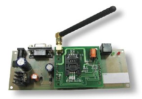
A GSM modem is a specialized type of modem which accepts a sim card, and operates over a subscrip- tion to a mobile operator, just like a mobile phone. From the mobile operator perspective, a GSM modem looks just like a mobile phone. When a GSM modem is connected to the controller, this allows controller to use the GSM mo- dem to communicate with the mobile network. While these GSM modems are most frequently used to provide mobile internet connectivity, many of them can also be used for sending and receiving SMS and MMS messages.
4.1 Signaling in GSM
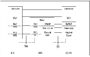
The various entities in the GSM network are connected to one another through signaling networks. Signaling is used for example, for subscriber mobility, subscriber registration, call establishment etc. The con- nections to the various entities are known as ‘reference points’. Examples include:
• A interface – the connection between MSC and BSC;
• Abis interface – the connection between BSC and BTS;
• D interface – the connection between MSC and HLR;
• Um interface – the radio connection between MS and
BTS.
Various signaling protocols are used over the reference points. Some of these protocols for GSM are the follow- ing:
• Mobile application part (MAP) – MAP is used for call con-
trol, subscriber registration, short message service, etc.; MAP is used over many of the GSM network interfaces;
• Base station system application part (BSSAP) – BSSAP is used over the A interface;
• Direct transfer application part (DTAP) – DTAP is used
between MS and MSC; DTAP is carried over the Abis and the A interface. DTAP is specified in GSM TS 04.08.
IJSER © 2011
http://www.ijser.org
International Journal of Scientific & Engineering Research, Volume 2, Issue 11, November-2011 4
ISSN 2229-5518
• ISDN user part (ISUP) – ISUP is the protocol for estab- lishing and releasing circuit switched calls. ISUP is also used in landline Integrated Services Digital Network (ISDN).
A circuit is the data channel that is established between two users in the network. Within ISDN, the data channel is generally a 64 kbit/s channel. The circuit is used for the transfer of the encoded speech or other data.
When it comes to call establishment, GSM makes a dis-
tinction between signaling and payload.
Signaling refers to the exchange of information for call set up; payload refers to the data that is transferred within a call, i.e. voice, video, fax etc.
For a mobile terminated GSM call, the signaling consists of exchange of MAP messages between GMSC, HLR and visited MSC (VMSC). The payload is transferred by the ISUP connection between GMSC and VMSC.
It is a continual aim to optimize the payload transfer through the network, as payload transfer has a direct cost aspect associated with it. Some network services are de- signed to optimize the payload transfer. One example is optimal routing.
4.2 GSM Modem
4.3 GSM Network
The GSM network consists mainly of the following functional parts:
• MSC – the mobile service switching centre (MSC) is the core switching entity in the network. The MSC is con- nected to the radio access network (RAN); the RAN is formed by the BSCs and BTSs within the Public Land Mobile Network (PLMN). Users of the GSM network are registered with an MSC; all calls to and from the user are controlled by the MSC. A GSM network has one or more MSCs, geographically distributed.
• VLR – the visitor location register (VLR) contains sub- scriber data for subscribers registered in an MSC. Every MSC contains a VLR. Although MSC and VLR are indivi- dually addressable, they are always contained in one in- tegrated node.
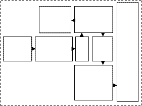

GSM BASED TWO NODE (MULTI NODE) EMBEDDED BAROMETERIC ALTIMETER
Display
Controller
Unit
Display
Controller
Unit
Barometer
Sensor
Instrumentation
Amplifier
Stepper
D
C Motor
Barometer
Sensor
Instrumentation
Amplifier
Stepper
D
C Motor
Wheel Ar-
rangement
Wheel Ar-
rangement
• GMSC – The Gateway MSC (GMSC) is the switching
entity that controls mobile terminating calls. When a call
is established towards a GSM subscriber, a GMSC con-
tacts the HLR of that subscriber, to obtain the address of
IJSER © 2011
http://www.ijser.org
International Journal of Scientific & Engineering Research Volume 2, Issue 11, November-2011 5
ISSN 2229-5518
the MSC where that subscriber is currently registered.
That MSC address is used to route the call to that sub- scriber.
• HLR –The Home Location Register (HLR) is the data- base that contains a subscription record for each sub- scriber of the network. A GSM subscriber is normally as- sociated with one particular HLR. The HLR is responsible for the sending of subscription data to the VLR (during registration) or GMSC (during mobile terminating call handling).
• CN – The Core Network (CN) consists of, amongst oth- er things, MSC(s), GMSC(s) and HLR(s). These entities are the main components for call handling and subscriber management. Other main entities in the CN are the equipment identification register (EIR) and authentication centre (AUC). CAMEL has no interaction with the EIR and AUC; hence EIR and AUC are not further discussed.
• BSS – The Base Station System (BSS) is composed of one or more base station controllers (BSC) and one or more base transceiver stations (BTS). The BTS contains one or more transceivers (TRX). The TRX is responsible for radio signal transmission and reception. BTS and BSC are con- nected through the Abis interface. The BSS is connected to the MSC through the A interface.
• MS – the mobile station (MS) is the GSM handset. The structure of the MS will be described in more detail in a next section. A GSM network is a public land mobile net- work (PLMN). Other types of PLMN are the time division multiple access (TDMA) network or code division mul- tiple access (CDMA) network.
V. CONCLUSION
The Altimeter, an incorporated barometer discovers its variety of application in the area of GPS system, weather stations & industrial systems. This paper illustrates the implementation of a MEMS pressure sensor in the design of a barometric altimeter which has significantly reduced the size and increased the accuracy of the barometric al- timeter. Furthermore a temperature sensor is interfaced with the system with the intention of implementing the dynamic temperature profiling approach as an attempt to remove the temperature dependent errors prevailing in present day standard temperature profiled altimeters. This methodology can be used to measure the altitude at different places by means of separate arrangement.
REFERENCES
[1] E. Manikandan, K. Immanuvel Arokia James, A. Kar-
thikeyan, ‚A Micro Electro Mechanical System
(MEMS) based Pressure Sensor in Barometric Altime-
ter‛ IJSER, Vol 2, Issue 8, August 2011.
[2] C.E. Lin, W.C. Huang, C.W. Hsu and C.C. Li, ‚Elec- tronic barometric altimeter in real time correction,‛ IEEE/AIAA 27th Digital Avionics Systems Confe- rence (DASC), Pp. 6.A.3-1 - 6.A.3-6, 2008.
[3] Zichen Zhu, Shenshu Xiong and Zhaoying Zhou, ‚A micro barometric altimeter with applications in alti- tude-holding flight control for MAVs,‛ Proceedings of the 21st IEEE Instrumentation and Measurement Technology Conference (IMTC), Vol. 2, Pp. 1039 –
1041, 2004.
[4] M. Tanigawa, H. Luinge, L. Schipper and Slycke,
‚Drift-free dynamic height sensor using MEMS IMU
aided by MEMS pressure sensor,‛ 5th Workshop on Positioning, Navigation and Communication (WPNC), Pp. 191 – 196, 2008.
[5] Qiang Zhou and Yabin Liu, ‚Novel barometric alti- meter system for vehicular testing of SINS,‛ 9th In- ternational Conference on Electronic Measurement & Instruments (ICEMI '09), Vol. 2, Pp. 491 – 493, 2009.
[6] R. Govindan, R. Kumar, S. Basu and A. Sarkar, ‚Al- timeter-Derived Ocean Wave Period Using Genetic Algorithm,‛ IEEE Geoscience and Remote Sensing Letters, Vol. 8, No. 2, Pp. 354 – 358, 2011.
[7] PIC Technologies, PIC Controller Operation guide –
David Benson.
[8] Programming and customizing the PIC microcontrol- ler – Micheal predco.
[9] Design with PIC microcontroller – John B.Peatman.
IJSER © 2011
http://www.ijser.org