International Journal of Scientific & Engineering Research, Volume 3, Issue 1, January-2012 1
ISSN 2229-5518
Future Internet Plan Using IPv6 Protocol
Krishna Kumar Mohbey, Sachin Tiwari
Abstract— Internet users are increases day by day then they want to access data more fastly and safely, so that higher capability internet services are very important. Today’s internet has the most of limitations which is important to remove. In future internet we used IPv6 protocol instead of IPv4 which have the larger address. It is important because the no. of users and system quantity are larger. In this paper we prepare the scope of future internet which will provide higher data transfer rates and high speed accessing to user. By designing new architecture and using new protocol version we can fastly access live TV and Multimedia data streaming on our computer. We can also enjoy the live video conferences because internet speed will be fast- er and powerful. Here we also describe the term dynamic caching which is important for accessing same data streaming on multiple places on the same time.
Index Terms— Future Internet (FI), FI Entry Point (FI-EP), IPv4, IPv6, Dynamic Caching
.
—————————— ——————————
ODAY, Internet is the most important information ex- change ecosystem. It has become the core communica- tion environment not only for business relations, but also
for social and human interaction. The immense success of Internet has created even higher expectations for new appli- cations and services, which the current Internet may not be able to support. Advances in video capturing and encoding have lead to massive creation of new multimedia content and applications, providing richer immersive experiences: 3D videos, interactive environments, network gaming, virtual worlds, etc. Thus, scientists and researchers from companies and research institutes world-wide are working towards rea- lizing the Future Internet.
The Future Internet (FI) is expected to be a holistic information exchange ecosystem, which will interface, inter- connect, integrate and expand today’s Internet, public and private intranets and networks of any type and scale, in or- der to provide efficiently, transparently, timely and securely any type of service (from best effort information retrieval to highly-demanding, performance critical services) to humans and systems. This complex networking environment may be considered from various interrelated perspectives: the net- works & infrastructure perspective, the services perspective and the media & information perspective.
The Future Media Internet is the FI viewpoint that covers the delivery, in-the-network adaptation/enrichment and consumption of media over the Future Internet ecosystem.
————————————————
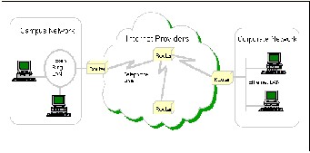
Here we define that how the content discovery, re- trieval and delivery take place in the current Internet. Users want text, audio, videos from YouTube or weather informa- tion, but they do not know or care on which machine the de- sired data or service reside. Information/content retrieval and delivery may be realized by today’s Internet network architecture as shown in Figure 1. The network consists of: a) Content Servers or Content Caches (either professional or user generated content and services), b) centralized or clus- tered Search Engines, c) core and edge Routers and optional- ly Residential Gateways (represented as R1 to R5) and d) Users connected via fixed, wireless or mobile terminals.
Figure 1: Today’s Internet Architecture
The first step is Content Discovery by the Search Engines: the Search Engines crawl the Internet to find, classify and index content and/or services. The second step is Content Discovery by the User: the user queries a Search Engine and gets as feedback a list of URLs where the content is stored. The last step is Content Delivery/Streaming: the user selects a URL and the content is delivered or streamed to him.
In order to show with an example the limitations of to-
day’s Internet, let us consider the simple case of the delivery
IJSER © 2012
International Journal of Scientific & Engineering Research, Volume 3, Issue 1, January-2012 2
ISSN 2229-5518
of a popular video from Content Server (e.g. a YouTube serv- er). If a few dozen of users from a large building block re- quest a video, the same video chunks will be streamed a few dozen of times. If a neighborhood has a few dozen of blocks, and a city a few hundreds neighborhoods, the very same video chucks will traverse the same network links thousands of times. If we continue aggregating at country and world- wide level, we will soon run out of existing bandwidth just for a single popular video stream.
This means that the three steps of content discovery and delivery can be significantly improved:
• (In the network) dynamic caching: If the content could be stored/cached closer to the end users, not only at the end- points as local proxies but also transparently in the network (routers, servers, nodes, data centre), then content delivery would have been more efficient.
•Content Identification: If the routers could identi- fy/analyses what content is flowing through them, and in some cases are able to replicate it efficiently, the search en- gines would gain much better knowledge of the content popularity and provide information -even when dealing with “live” video streams.
•Network topology & traffic: If the network topology and the network traffic per link were known, the best end-to-end path (less congestion, lower delay, more bandwidth) would be selected for data delivery.
•Content Centric Delivery: If the content caching location, the network topology and traffic were known, more efficient content-aware delivery could be achieved based on the con- tent name, rather than where the content is initially located.
•Dynamic Content Adaptation & Enrichment: If the con- tent could be interactively adapted and even enriched in the network, the user experience would be improved.
We envision an FI architecture which will consist of different virtual hierarchies of nodes (overlays), with different func- tionalities. In Figure 3, 3 layers are depicted; however this model would be easily scaled to multiple levels of hierarchy (even mesh instantiations, where nodes may belong to more than one layer) and multiple variations, based on the content and the service delivery requirements and constraints.
In a realistic roll-out scenario, the FI deployment is
expected to be incremental. This is because we expect that
today’s existing legacy network nodes (core routers, switch- es, access points) will not only remain and will even be the majority for a number of years; thus the proposed architec- ture should be backwards compatible with current Internet deployment. As shown in Figure 2, the Service/Network Provider Infrastructure Overlay is located at the lower layer. Users are considered as Content Producers (user generated content) and Consumers (we can then call them “Prosu- mers”).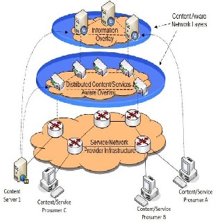
Figure 2: FI high level architecture
This Network Infrastructure Overlay is the service, ISP and network provider network infrastructure, which consists of nodes with limited functionality and intelligence (due to the cost of the network constraints) . Content will be routed, as- suming basic quality requirements and if possible and needed cached in this layer. The medium layer is the Distri- buted Content/Services Aware Overlay. Content-Aware Network Nodes (e.g. edge routers, home gateways, terminal devices) will be located at this overlay. These nodes will have the intelligence to filter content and Web services that flow through them (e.g. via deep packet Inspection or signalling processing), identify streaming sessions and traffic (via sig- nalling analysis) and provide qualification of the content. This information will be reported to the higher layer of hie- rarchy (Information Overlay). Virtual overlays (not shown in the figure) may be considered or dynamically constructed at this layer. We may consider overlays for specific purposes e.g. content caching, content classification (and depending on the future capabilities, indexing), network monitoring, con- tent adaptation, optimal delivery/streaming. With respect to content delivery, nodes at this layer may operate as hybrid client-server and/or peer-to-peer (P2P) networks, according to the delivery requirements. As the nodes will have infor- mation about the content and the content type/context that they deliver, hybrid topologies may be constructed, custo- mized for streaming complex media such as Scalable Video Coding (SVC), Multi-view Video Coding (MVC). At the highest layer, the Content/Services Information Overlay can be found. It will consist of intelligent nodes or servers that have a distributed knowledge of both the content/web- service location/caching and the (mobile) network instantia- tion/ conditions. Based on the actual network deployment
IJSER © 2012
International Journal of Scientific & Engineering Research, Volume 3, Issue 1, January-2012 3
ISSN 2229-5518
and instantiation, the service scenario, the service require- ments and the service quality agreements, these nodes may vary from unreliable peers in a P2P topology to secure corpo- rate routers or even Data Centers in a distributed carrier- grade cloud network. The content may be stored/cached at the Information Overlay or at lower hierarchy layers. Though the Information overlay we can be always aware of the con- tent/services location/caching and the network information. Based on this information, a decision on the way that content will be optimally retrieved and delivered to the subscribers or inquiring users or services can be made.
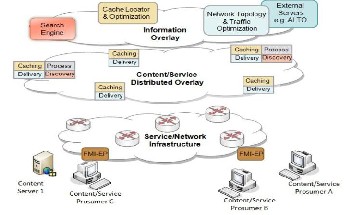
As already explained, due to network planning cost limita- tions and the need for reusability of the existing infrastruc- ture, it is expected that different nodes in the network may not host all stratums and/or host subsets of the proposed functionality of each stratum. Based on this assumption, Fig- ure 3 shows a hierarchical view of the FI network architec- ture. The main functionality of FI resides in the content and services distributed overlay, where we have defined the fol- lowing functional modules/entities:
•Delivery Nodes: They are responsible for the content & services delivery, IP acceleration and efficient content streaming (including P2P overlays creation).
•Caching Nodes: They are responsible for content caching, caching optimization and content replacement in collabora- tion with the cache content optimization entity.
•Discovery Nodes: They contribute to the discovery of new and calculating the popularity of known services and content (stored or streaming). They also measure traffic ana- lytics and help towards network topology discovery.
•Process Nodes: They are responsible for services processing in-the network and content adaptation & enrich- ment.
An assumption would be that delivery and caching nodes’ functionality would co-exist in most cases, followed by the discovery and the processing functionality.
Figure 3: Future Internet network architecture
The proposed FI functionality may be fully distributed at the content/services distributed overlay. For our explanation, for presentation and simplicity reasons, we may assume that some functionality is provided by an additional Information Overlay, which handles the following functional mod- ules/entities:
•Search Engine: It is a distributed system that discovers and indexes the content and the services, processes the queries from the users and returns relevant results ordered accord- ing to several criteria. It may also be considered at an appli- cation overlay.
•Content Cache Locator & Optimizer: This entity may exist as a group of dedicated physical nodes or may be a fully dis- tributed abstract functionality. The locator module will redi- rect content requests to the “best” cached copy, where “best” is defined based on perceived Quality of Service (PQoS) of the user. In order to make the decision it may also communi- cate with the network/traffic monitor entity. The optimizer module will support caches in deciding which object they should store or evict.
•Network Topology/Traffic Optimizer: It is responsible for gathering all network related information: topology, traffic, characteristics of the user Internet access and optionally user location.
•Finally, as entry points to the FI we have defined the FI Entry Point (FI-EP). The FI-EP may be hosted at a local rou- ter or a Residential Gateway and is responsible for seamless operation, termination of FI protocol stack processes (e.g. receiving and adapting content delivery) and optimal con- tent fetching and streaming.
One may notice that some functionality could be ag- gregated in less functional entities or that some entities could be removed. For example, the FI-EP module may be over- loaded to perform also the Content Cache Locator role, whe- reas the Cache optimizer would be distributed at the overlay network. Indeed, this may depend on the final implementa- tion approach chosen (as the purpose of this section was to emphasize the functional blocks, rather than propose an ac- tual instantiation).
The Internet Engineering Task Force published the IPv4 specification (RFC 791) in the fall of 198l. When the IPv4 specification was released, the Internet was a community of approximately one thousand systems. The IPv4 specification called for every IP address to be represented by a 32-bit number made up of four groups of eight-bit numbers. This
IJSER © 2012
International Journal of Scientific & Engineering Research, Volume 3, Issue 1, January-2012 4
ISSN 2229-5518
provides a total of just over four billion addresses, although only a few hundred million are actually available due to hie- rarchic allocation schemes. Since the release of IPv4, the In- ternet population has grown to over 100 million Computers, increasing far faster than anticipated. As the pool of available addresses decreases, it will become increasingly difficult to obtain IPv4 addresses. Furthermore, the pace of this growth is expected to continue for years to come.
The bottom line is this: The Internet is running out of addresses. And by some hard estimates, this could happen as soon as. Early IP assignments reserved addresses for some corporations and institutions in very large blocks. These “Class A” and “Class B” network assignments were issued in the early days when the current growth was not anticipated. While some early adopters may still have addresses available for internal usage, the pool of unissued addresses is becom- ing smaller every day. The addresses that were handed out to some of the early large corporate networks cannot now be reissued to other users.
IPv6 was designed to take an evolutionary step from IPv4. It was not a design goal to take a radical step away from IPv4. Functions that work in IPv4 were kept in IPv6. Functions that didn't work were removed.
IPv6 Header Format
The most important changes introduced in IPv6 are evident in the header format:
Expanded addressing capabilities. IPv6 increases the size of the IP address from 32 to 128 bits. This ensures that the world won't run out of IP addresses. In addition to unicast and multicast addresses, a new type of address, called an anycast address, has also been introduced.
A streamlined 40-byte header. As discussed below, a number of IPv4 fields have been dropped or made optional. The result- ing 40-byte fixed-length header allows
For faster processing of the IP datagram. A new encoding of options allows for more flexible options processing.
Flow labeling and priority. IPv6 has an elusive definition of a "flow". This new idea allows the labeling of packets belong- ing to particular flows. The IPv6 header also has an eight-bit Traffic Class field. This field, like the TOS field in IPv4, can be used to give priority to certain packets within a flow, or it can be used to give priority to datagrams from certain appli- cations over datagrams from other applications.
IPv6 addresses are 128-bit identifiers for interfaces and sets of interfaces. There are three types of addresses: [2]
Unicast: An identifier for a single interface. A packet sent to a unicast address is delivered to the interface identified by that address.
Anycast: An identifier for a set of interfaces (typically be- longing to different nodes). A packet sent to an anycast ad- dress is delivered to one of the interfaces identified by that address (the "nearest" one, according to the routing protocols' measure of distance).
Multicast: An identifier for a set of interfaces (typically be- longing to different nodes). A packet sent to a multicast ad- dress is delivered to all interfaces identified by that address.
There are no broadcast addresses in IPv6, their func- tion being superseded by multicast addresses. IPv6 addresses of all types are assigned to interfaces, not nodes. An IPv6 unicast address refers to a single interface. Since each inter- face belongs to a single node, any of that node's interfaces' unicast addresses may be used as an identifier for the node. All interfaces are required to have at least one link-local un- icast address. A single interface may also be assigned mul- tiple IPv6 addresses of any type (unicast, anycast and multi- cast) or scope. Unicast addresses with scope greater than link-scope are not needed for interfaces that are not used as the origin or destination of any IPv6 packets to or from non- neighbors. This is sometimes convenient for point-to-point interfaces.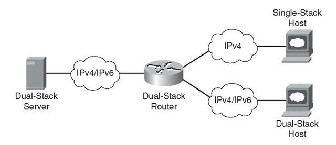
The IPv6 specification has several possible APIs to enable IPv6 communications, and most are IP-version inde- pendent. By using these APIs, developers can write a single segment of code that will support both IPv4 and IPv6 com- munications. Based on the name of the system that is the tar- get of communication and the configuration of the current node, the API will determine the target IP address and whether it’s using IPv4 or IPv6 protocol. By using IP version independent APIs, developers can enable. There is very little doubt that, for an extended period of time, the Internet will be made up of both IPv4 and IPv6 hosts. For that reason, the IPv6 basic socket API supports both IPv4 and IPv6. This ap- proach is called a dual-stack interface. Once an Application has been upgraded to the IPv6 socket interface; no more code is required to enable communication with both IPv4 and IPv6 systems.
IJSER © 2012
International Journal of Scientific & Engineering Research, Volume 3, Issue 1, January-2012 5
ISSN 2229-5518
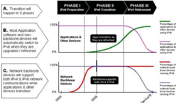
When a call is made to the new socket interface, it will look at the data structures and determine if it is possible to commu- nicate with this node using IPv6. If not, the socket will auto- matically make the connection using an IPv4 protocol con- nection. Since all current Internet software use IPv4, a dual- stack IPv6 application can communicate using IPv4 to all current software without any additional coding of the IPv4 applications. IPv6 communication transparently. Figure 5 shows the transition strategy of IPv6 over IPv4.
Address Difference in IPv4 and IPv6
• IPv4:
4,294,967,296
• IPv6:
340,282,366,920,938,463,374,607,432,768,211,456
In this paper we find the architecture for future internet which uses the IPv6 protocol or the combination of IPV4 and IPv6. This architecture is most useful for transmission of the live data streams like video from YouTube or live TV. Here we also conclude the topologies, caching and delivery process for the future multimedia internet. This architecture is important because the no. of users’ ratio increasing rapid- ly, so we required more unique address which is only possi- ble by the IPV6 over IPv4.
Acknowledgments
Mr.Krishna Kumar Mohbey and Sachin Tiwari, Authors of
this paper are Thankful to IJSER Reviewers and committee for accepting this paper for the online journal publishing.
References
[1] IPv6 and the Future of the Internet A Technical White Paper Sun
Microsystems, Inc. 1.512.434.1511
[2] Peter J. Tseronis , Architecting Next-generation Internet Technolo- gies, PMP Chair, Federal IPv6 Working Group October 22, 2008
[3] “Future Media Internet Architecture Think Tank” White Paper Fu- ture Media Internet Architecture Reference Model (v1.0)
[4] http://www.isi-initiative.org/ISI_Future_Internet_Position_ Pa- per_v10_0_APPROVED.pdf
[5] Arun Seehray, Jad Naousz, Michael Walfishy, David Mazi`eresz, Antonio Nicolosix, and Scott Shenker, A policy framework for the future Internet
[6] next generation internet initiative National Coordination Office for
Computing, Information, and Communications
[7] Security Challenges in the future mobile Internet Bernd Lamparter, Dirk Westhoff NEC Europe Ltd., Adenauerplatz 6, D-69115 Heidel- berg.
[8] http://www.ceiusa.com/papers/internet.html
[9] James F. Kurose, “Computer Networking: A Top-Down Approach
Featuring the Internet”, 2001 (ISBN 0-201-47711-4)
[10] IPv6 – The Next Generation Internet Protocol ,Yuanlei Zhang
IJSER © 2012
International Journal of Scientific & Engineering Research, Volume 3, Issue 1, January-2012 6
ISSN 2229-5518
IJSER © 2012