International Journal of Scientific & Engineering Research, Volume 6, Issue 3, March-2015 746
ISSN 2229-5518
Fortification of Multiple Parallel Assay Operations with Cross Contamination Avoidance in a Restricted Biochip
Debasis Dhal, Arpan Chakraborty, Piyali Datta, Sudipta Roy, and Rajat Kumar Pal
Abstract—Digital microfluidic biochips are modification many areas of Biochemistry, Biomedical sciences, and Microelectronics. It is also known as ‘Lab-on-a-Chip’ for its recognition as an alternative to laboratory experiments. In recent times, because of urgency and cost efficacy, several assay operations are required to be performed at the same time. So, parallelism is a must in designing biochips. Having an area of a given chip as a constraint, how efficiently we can use a restricted sized chip and how much parallelism can be built-in are the objectives of this paper. A specific application of an assay may characterize a sample where, say only one type of reagent and multiple samples have been considered, or vice versa, and determine some parameter(s) of the sample(s) under requirement in parallel. In our experimentation, we essentially do this task in parallel for five such sets of sub-regions of a given restricted sized chip in digital microfluidics using an array based partitioning pin assignment technique, where cross contamination problem has also been considered, and efficiency of proper taxonomy of a given sample has also been enriched.
Index Terms— Lab-on-a-chip, Cross contamination, Design automation, Sample, Reagent, Wash droplet, Pin constrained design, Algorithm, Parallelism.
1 INTRODUCTION
—————————— ——————————
N modern years, there are huge revolutions in terms of per- formance and efficiency while using biochips to detect the parameters of samples. It is the most advanced device nowa- days in the micro level for diagnosing (analyzing, testing, and detecting) some specimen like DNA, blood, saliva, stool, cough, urine, and many others that we like to examine in our everyday life. There are some challenging scopes to better- ment the performance of this biochip. This device is also known as DMFS (Digital Microfluidic System) [1, 2, 5, 6, 8] and/or DMFB (Digital Microfluidic Biochip). It can perform all the tasks of droplet creation, transportation, mixing, and sensing that are much more cost-effective and time-effective in
comparison to that we usually do in our chemistry classes. Droplet based digital microfluidics are technologies that pro- vide fluid-handling capability on a chip. Bio-chemical fluids are represented in the form of tiny droplets and they integrate on-chip various bioassay operations such as sample prepara- tion, routing, mixing, detection, etc. In comparison to conven- tional laboratory procedure, which is time consuming, expen- sive, and also erroneous due to manual involvement, all these tasks could be programmed and the movement of droplets could be entirely automated, even as it is desired by perform- ing each part of the laboratory experimentation on a chip, which we call ‘Lab-on-a-Chip’ (LOC). In biochemistry and
————————————————
Debasis Dhal and Sudipta Roy are with the Assam University, Silchar, As- sam, India (e-mail: todevcse@redifmail.com, sudipta.it@gmail.com).
Arpan Chakraborty, Piyali Datta, and Rajat Kumar Pal are with the Depart- ment of Computer Science and Engineering, University of Calcutta, Kolkata, India (e-mail: arpan250506@gmail.com, piyalidatta150888@gmail.com, pal.rajatk@gmail.com).
biomedical sciences, microfluidic biochips are of much im- portance. These devices operate on microliter or nanoliter vol- ume of biological samples which are routed throughout the chip using electrowetting in a ‘digital’ manner under clock control on a 2D array of electrodes [22]. These electrodes in a DMFB combine Electronics with Biology and integrate various bioassay operations from sample preparation to detection. The foremost objective is to minimize the time required to get the wanted outcome of the assay while perfect result is obviously obtained.
1.1 The Digital Microfluidic System (DMFS)
The name of the device DMFS is commonly known as Electro- Wetting-on-Dielectric (EWOD) toolkit [8]. This EWOD is usu- ally made with the help of many number of unit cells. It makes a two-dimensional (2D) array. The basic EWD device is based on charge control manipulation at the solution / insulator in- terface of discrete droplets by applying voltage to a control electrode. Electrowetting on dielectric (EWD) is the phenome- non where an electric field modifies the wetting behaviour of a polarizable and/or conductive liquid droplet of sample or reagent in contact with a hydrophobic, insulated electrode. A voltage is applied between the liquid and the electrode, and it results in an electric field across the insulator. As a conse- quence, the interfacial tension between the liquid and the insu- lator surface decreases. The voltage applied to a series of adja- cent electrodes, which can be turned on or off, introduces an interfacial tension gradient that can be applied to manipulate the movement of droplets [8].
Fig. 1(a) shows a typical m×n 2D array of microfluidic bio- chip holding two droplets and one detection site. Fig. 1(b)
IJSER © 2015 http://www.ijser.org
International Journal of Scientific & Engineering Research, Volume 6, Issue 3, March-2015 747
ISSN 2229-5518
shows the side view of the biochip. It also represents a typical detection site, which can optically detect a mixed droplet and generate some results. This site (or electrode) should be trans- parent so that light can pass through it. One LED is located in one side and in the opposite side a photo electric diode is placed. When the LED glows and some light pass through the electrode and the mixed droplet, the diode measures the in- tensity of the light and draws some voltage against the intensi- ty. Against this voltage we can predict some outcome. The droplet is sandwiched in between two plates that are known as top plate and bottom plate. The top plate contains ground electrode and the bottom plate contains control electrodes.
minimum number of pins, i.e., the provision for availability of a minimum number of distinct input voltages. In biomedical sciences, we may have to perform the operations as mentioned in the following cases:
Case I: Same diagnosis may have to be performed on mul- tiple samples. So, there can be one reagent which is to be mixed with different samples separately and then optical de- tection is made.
Case II: Different diagnosis may have to be performed on a particular sample with the help of several reagents which are to be mixed with one sample in isolation and then it is sent for detection optically.

Detection site
Droplets
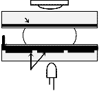
Photodiode
Top plate
Case III: In order to achieve good approximation, some- times it is required to perform same diagnosis on a particular
Electrical pad
Ground electrode Glass substrate
Insulation
sample several times, and then the average of the results is
considered for further processing.
The abovementioned cases are very much time consuming
Droplet
Fluid layer
even using an LOC. To reduce the total time and to get accu-
Electrowetting electrode
Glass substrate
Bottom plate
Control electrodes LED
rate results in a reasonable amount of time, often the task(s) is (are) required to be performed in parallel. Hence, several op- erations often could be executed at the same time. Mixing be-
(a) (b)
Fig. 1. (a) Top view of a microfluidic array with two droplets and a detec- tion site. (b) A cross-sectional side view of digital microfluidic platform (of a cell) with a conductive glass plate present in a detection site referring to Fig. 1(a).
In the past, many small devices are invented those are ca- pable to perform a particular job, such as detector that can detect particular signals, flow sensors which can determine the intensity of flow only. But EWOD is a combination of many such devices, which can complete many tasks like transporta- tion of liquid, divide one droplet into two droplets, merging of two droplets, detecting and discarding, and so on, where a particular substance may be present in these droplets simulta- neously. Some of the characteristics of such a device are as follows: higher throughput, minimal human intervention, smaller sample / reagent consumption, higher sensitivity, im- proved yield, and so on and so forth [6, 8, 13].
The concept of DMFS occurred only in two decades back. The key sense of DMFS is that the unit volume of some fluid under test is constant. It depends on the geometry of the sys- tem. This system is based on volume flow rate and again the volume flow rate is based on the number of droplets trans- ported. This is how a droplet constitutes the fluid volume. The volume of these droplets may be several microliters. These very small amounts of liquid act on the principle of modulat- ing the interfacial tension between a liquid and an electrode coated with a dielectric layer [8]. An electric field established in the dielectric layer creates an inequality of interfacial ten- sion, if the electric field is applied to only one end of the drop- let on an array that forces the droplet to move. Typically, 20–
80 V is applied to each electrode [6, 8].
1.2. The Problem and Its Importance
To get high throughput, multiple bioassay operations must be done parallel. At the same time we have to avoid droplet interference as well as contamination problems at the cost of
tween proper reagent and sample is the main operation, which
takes maximum time [5, 16] with respect to transportation and
detection of the droplets. So, we require to adopt parallel dis-
tribution of the reagent and/or the sample to proper region on a chip such that mixing can be performed in parallel. In our design procedure we like to formulate a technique that en- sures performance as well as efficiency of the detection pro-
cess in a reasonable amount of time in parallel. Here we focus to take a kind of design procedure which can be used in the above cases that needs massive parallelism. We consider the first among the three cases stated above. So, the reagent is of one type and different samples are used for their respective detection.
2 Some Fundamental Tasks and Inherent
Constraints
2.1 Fundamental Tasks
In this section, we define some terms coupled to the problem of DMFS in a few words. We know that in such a chip droplets are dispensed from the outside of an array. So, there are sev- eral sources of droplets; these are either sample droplet that we like to test or reagent droplet that is mixed with sample for detection, or wash droplet for washing the cells used for drop- let movement.
Droplet creation [5, 11]: Droplet formation is a process of creating droplet of a desired size from a source (of larger vol- ume) of the element (sample or reagent or wash droplet) we like to dispose into the array perpendicularly by activation and deactivation of adjacent electrodes. It is an additional task of creating a droplet that is performed outside the array for a minimum of three clock pulses. In general, droplet sources are outside the periphery of the chip. By activating three consecu- tive electrodes adjacent to the source the fluid is extended throughout the three electrodes. Then the two consecutive electrodes are deactivated while the third one remains activat- ed. As a consequence, the fluid (sample or reagent) is separat-
IJSER © 2015 http://www.ijser.org
International Journal of Scientific & Engineering Research, Volume 6, Issue 3, March-2015 748
ISSN 2229-5518
ed on the third electrode in the form of a droplet of desired size, i.e., to be handled by a single electrode.
Routing path [3, 4, 6]: This is the passageway that a droplet uses for its movement following nearby cells of an array through a synchronized activation and deactivation of the electrodes considering a predefined schedule. This path may route from a source to a mixer, then from a mixer to a detec- tion site, and then from there to a sink. Such a path is usually measured by the number of cells belonging from a port / module to another port / module.
Mixer and mixing operation [13, 16, 20, 21]: This is a mod- ule in an array where the most important task of mixing hap- pens. Here different sample(s) and reagent(s) come from their respective sources and are mixed for detection. This mixing operation takes the maximum amount of time needed for an assay. So, it dominates other operations in an assay in terms of time required. Mixing is sometimes physical reaction and at times chemical reaction. There is a variety of mixing proce- dure including diffusion of two droplets to be mixed.
Detection site [22]: Detection site is a small module usually formed by a single cell in the array that helps to detect the pa- rameters present in a sample. Generally, it is done on mixed droplets, but it may also be required to detect a sample or rea- gent before mixing. Usually, the number of detection sites is not many (as it is a costly module) and their sites are also ten- tatively fixed.
Assay [1-7]: An assay is a whole operation that includes creation of droplets, their mixing, and detection of a sample’s condition (either regular or irregular; if irregular, then how
communicate between different modules.
of droplets, mixing of droplets, detecting some factors present in a sample, and many others. Obviously, some problem relat- ed constraints are there; some of which are fluidic constraint, electrode constraint, time constraint, and area constraint, as briefly discussed below.
Fluidic constraint: At the time of droplet routing, in static condition, at least one cell is supposed to be kept in between two electrodes containing two droplets to prevent unintended mixing. During movement of droplets following a particular direction, we may observe that at least a gap of two electrodes is must to avoid unwanted mixing. Hence, static and dynamic fluidic constraints [3, 16] are introduced, as these are necessary for a pair of droplets for their minimum separation on a bioas- say.
Electrode constraint [3, 4]: In case of pin constrained de- sign, more than one electrodes are controlled by a single pin. This may introduce unwanted effect of voltage on some elec- trode, and as a result this electrode may activate a droplet staying in an adjacent electrode inadvertently. Thus, the drop- lets may not move following a given schedule. This imposes several constraints during routing. If we can make proper voltage assignment over the pins, truthful movement of drop- lets can be guaranteed.
Timing constraint [3, 4]: Timing constraint in droplet rout-
ing is given by an upper bound on droplet transportation time. It is defined to have the proper synchronization among all the bioassay operations held in different modules. All the operations are pre-scheduled and the result should be out within some specified time limit. So, there is an upper bound on time for each operation, which is referred to as the timing constraint.
Area constraint [3, 4]: We want to perform all the bioassays in a minimum chip area in view of all the above-mentioned constraints. All kinds of assignments include droplet transpor- tation from the source of droplet to the mixing region and also to the detection site. A mixing region is supposed to be located in a proper position for utilization of total array area. So a de- sign must support how efficiently a chip of some fixed area can be utilized. Though we are supposed to satisfy all the con- straints in isolation, maintaining all the constraints for some bioassay may introduce the problem of cross contamination.
Cross contamination problem [3, 4]: When the residue of one droplet transfers to another droplet with undesirable con- sequences, cross contamination occurs, such as misleading assay outcomes, i.e., incorrect diagnosis. The problem of cross contamination may also occur when a common path is shared by two distinct droplets by fulfilling their timing constraint.

Sequencing graph [3, 4]: The vertices represent the assay operations (dispensing, mixing, detection, etc.) and the edges represent their mutual dependencies. This method allows user to describe bioassay at a high level of abstraction and it auto- matically maps behavioural description to the underlying mi- crofluidic array.

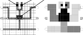
5
1 2 3
4
(a) (b) (c)
Fig. 2. (a) 25 pins are needed to cover all electrodes of a 5×5 array by direct addressing method. (b) Pin number 2 is a droplet holder that has four direct neighbour pins 1, 3, 4, and 5. (c) A 5×5 array is covered by five pins using Connect-5 algorithm.
3 A BRIEF SURVEY ON PIN CONFIGURATION
3.1. Pin Configuration of an Array Area
The DMFS, which is known as lab-on-a-chip, is being tried to have a massive parallelism in bio-assay analysis. It requires parallel droplet movements on a fixed size chip, i.e., concur- rent movement of droplets are performed by the predeter- mined and proper sequence of activation and deactivation of electrodes under the control of some external control pins. So, the pin configuration must be so chosen that we can achieve best performance in droplet transportation, which is simple and straightforward.
A. Direct Addressing Pin Configuration [3-4, 15, 17]:
To move a droplet, activation and deactivation of appropriate electrodes are required. So, every electrode must be controlled by some control pin to provide the necessary actuation volt- age. The easiest procedure to assign pins to electrodes is to
IJSER © 2015 http://www.ijser.org
International Journal of Scientific & Engineering Research, Volume 6, Issue 3, March-2015 749
ISSN 2229-5518
allot individual control pins. So, the number of pins required for an n×n array is n2; a model array is shown in Fig. 2(a). A method of partitioning based on array may greatly reduce pin number as stated below.
B. Array based Partitioning [3-4, 9, 12, 19]:
An array based partitioning is simple and efficient in respect of the number of distinct voltages we are supposed to provide as input. The chip is divided into some partitions depending on the activities performed there and an optimum number of pins are introduced to assign the electrodes of the partition. These partitions can be repeated anywhere on a chip to reduce the total number of control pins in the chip. If array based par- titioning is done using Connect-5 algorithm [4, 15], then we may find that here any pin has four distinct immediate adja- cent neighbours; see in Fig. 2(b). Thus, we obtain an array of any size by assigning only five pins as shown in Fig. 2(c). Though only five pins are sufficient to assign all the electrodes on an array of any size, only a single droplet can safely be al- lowed to move in such a huge area.
As a remedy of this problem the concept of cross referencing is introduced.
C. Cross Referencing [3-4, 8, 18]:
As a remedy to the problem of using n2 number of distinct pins for an n×n array of electrodes, array based partitioning method is greatly efficient. But electrode constraint is again a hazard to this newly introduced method. Hence, a pin con- strained design technique is introduced, namely cross refer- encing [4, 9, 18], where only m+n number of control pins are required to assign to all the electrodes in an m×n array. In this case, the electrode to be actuated is defined by the row and column number whose intersection contains a next-active (droplet holding) electrode. A next-active electrode is certainly such an adjacent electrode of an electrode that currently holds a droplet.
A method named after cross referencing [4, 9, 18] has been introduced to directly decide the voltage to be applied (HIGH or LOW) at the row and column combination for proper movement of a droplet. Instead of many advantages of this pin assignment technique, there are some disadvantages too.
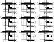
1 2 3 4 5
3 4 5 1 2
5 1 2 3 4
2 3 4 5 1
4 5 1 2 3


(a)
1 2 3 4 5
3 4 5 1 2
5 1 2 3 4
1 2 3 4 5
3 4 5 1 2
5 1 2 3 4
2 3 4 5 1
4 5 1 2 3


(b)
1 2 3 4 5
3 4 5 1 2
5 1 2 3 4
When we activate a row and a column for moving a droplet using HIGH-LOW or LOW-HIGH combination, then some unwanted cells might also be activated that may allow un- wanted movement of droplet(s). The following example of a part of scheduling shows this problem. To authorize only wanted movements, electrode constraints have been intro- duced accordingly. Incidentally, for a large array with a num- ber of droplets, it has been proved that the problem of satisfy- ing electrode constraints towards a desired solution is an NP- hard problem [3, 9, 23].
2 3 4 5 1
2 3 4 5 1
4 5 1 2 3
(c)
4 5 1 2 3
(d)
D. Broadcasting [3, 4, 14]:
In broadcasting, control pins are assigned to electrodes taking into account the movement of droplets which is predefined in
Fig. 3. (a) Both the droplets are on same pin and both of them intend to move to the same pin. (b) Safe movement is possible to pin 3. (c) Both the droplets are on same pin, but aimed to move to different directions. (d) Both the droplets stuck between the two diagonally activated electrodes.
Through the use of Connect-5 algorithm, electrodes in an array of any size can be assigned to pins. Now, if there are more than one droplets to move to different directions, elec- trode interference may occur; so that some of the electrodes in the array become activated due to the sharing of a set of five pins by all the electrodes and it results in undesired move- ment, mixing and splitting of the droplets, or resulting in stuck droplet and thus the performance of the whole chip de- grades. In Fig. 3(a), there are two droplets each on pin 1 and tends to move to pin 3. As a result, pin 3 is activated simulta- neously deactivating pin 1 and both the droplets move to their destined position safely as shown in Fig. 3(b). On the other hand, in Fig. 3(c), the droplets are on pin 3 and D1 is to move rightward to pin 4 whereas D2 is to move upward to pin 1. So, pins 1 and 4 are activated simultaneously deactivating pin 3. It results in stuck droplets at the junction of pins 1 and 4, as both of them are activated at a time as shown in Fig. 3(d). This type of unwanted circumstances is known as electrode interference.
terms of scheduling of a complete assay, i.e., the activation- deactivation sequence of electrodes. It is stored in a microcon- troller in digital term and the electrodes used to route a drop- let is assigned to a control pin maintaining that activation- deactivation sequence. Thus, for a specific bioassay it reduces the number of pins significantly and hence no electrode inter- ference occurs. In case of pin constrained design, more than one electrodes are controlled by a single pin. It is voltage effi- cient, but there is a deficiency that if more than one droplets are to move we have to maintain electrode constraints as well. In this paper, we have adopted the notion of broadcasting to develop a pin configuration of a restricted sized chip for a set of parallel bioassay operations.
4 A 15×15 ARRAY FOR SEQUENTIAL PROCESSING
4.1. The Existing Assay Operation
A DMFB is shown in Fig. 4(a) that contains a restricted sized array of capacity 15×15 cells for performing a multiplexed bio- chemical assay consisting of a glucose assay and a lactate as- say based on colorimetric enzymatic reaction [6, 17]. In other words, in such an array two operations can be performed on two samples and two reagents one after another [5, 6, 14].
IJSER © 2015 http://www.ijser.org
International Journal of Scientific & Engineering Research, Volume 6, Issue 3, March-2015 750
ISSN 2229-5518
Here, only one shared mixer is used, where a first sample (say S1 ) and a first reagent (say R1 ) are routed from their respective sources to the mixer and after a desired level of mixing, the mixed droplet is then routed to detection site 1 (D1 ) for neces- sary finding(s). After completion of this phase, a second sam- ple (say S2 ) and a second reagent (say R2 ), in a similar manner from their respective origins, route to the mixer for their mix- ing and then the mixed droplet goes to detection site 2 (D2) for necessary outcome(s).
So, there must be a delay between the said two operations as the array contains a common mixer, some path below the mixer is common to different reagents, and some path above the mixer is common to different mixed droplets to respective detection sites. Hence, washing is necessary in between every alternative assay; otherwise, unwanted contamination of re- sidual samples, reagents, and mixed droplets might cause for erroneous results.
4.2. An Alteration over the 15×15 Array
A modification of the previous array (in Fig. 4) has been pro- posed by Hwang et al. [2, 14], where the array size is reduced to 10×10, the number of partitions is reduced to four, and the mixer size is 2×2 (instead of 2×3) as shown in Fig. 5(a). Though this modification reduces the number of pins required but yet the mixing or detection is sequential in nature as the number of mixers is not increased. In Fig. 5(b), we may observe that the mixing region of the array is the junction of four partitions (taking only one cell from each of the partitions), so several droplets (as necessary) can move to this region for mixing. Here the droplets do not suffer by the limitations of Connect-5 algorithm; rather, the pin number is also reduced by 20% (as only four instead of five modules are present in this modifica- tion over the earlier array).
4.3. Prerequisites and Objectives towards Parallelism
Detection site 1 Detection site 2
2×3 array mixer
There are several assumptions and concerns to achieve the goals in performing bioassay operations; some of which are as
Sample 1
Test droplet source
Reagent 1
(a)
Sample 2
S1
Droplet sink
Reagent 2
R1
S2
R2
(b)
follows: (1) A sequencing graph that tells about the flow of exe- cution of an assay; accordingly, we are supposed to frame a minimum array area required. (2) The assay response time that includes routing of droplets, mixing, detecting, and washing for making the array ready for a next assay operation, is the next important factor that we like to minimize. (3) The voltage distribution in terms of the number of distinct control pins as- signed to electrodes for a set of assays is also to be minimized. The use of less number of pins makes a design less complex
Fig. 4. (a) A 15×15 array layout of droplet routing containing two sources of samples and two sources of reagents with one 2×3 mixer and two de- tection sites. Direction of arrows shows the movement of droplet(s) (either sample, or reagent, or mixed droplet) along the paths. (b) Pin assignment of the array using Connect-5 algorithm that covers all the distinct cells and uses not more than 25 pins. Here for the movement of a droplet, the adja- cent cells are used as guard band; hence for a mixer of size 2×3, an array of size 4×5 is deployed for its realization.
for synchronized activation and deactivation of electrodes.
Now, mixing is the most important operation in this pro-
cess as mixing time dominates the total completion time of a
bioassay. So mixing must be efficient with respect to time and
area required. There is a variety of mixing procedures from
which appropriate process must be chosen, such that the area
requirement as well as the time and cost requirement are op-


timum.
The aforesaid operations may be achieved by applying the
Connect-5 structure [5, 6] of pin assignment as shown in Fig.
4(b). Thus, for a pair of samples and for a pair of reagents, six
different combinations of mixing are S1 -R1 , S1 -R2 , S2 -R1 , S2 - R2 , S1 -R1 -R2 , and S2 -R1 -R2 for their subsequent detections in


(a) (b)


(c) (d)
different time instant [7], where washing is necessary in be-
tween two assay operations to avoid cross contamination [14].
(e)
(f)
(g)
(h)
Sample 1
Reagent 1

Detection sites
(a)

Sample 2
S1
2×2 mixer
Reagent 2
R1
S2
R2
(b)
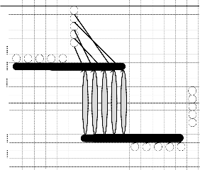
Fig. 6. A mixer of array size 1×3, and its working principle. (a) Two drop- lets are present on two extreme electrodes. (b) Mixing of two droplets into a single droplet at the middle electrode. (c) The double droplet moves toward the left electrode. (d) The double droplet moves toward the middle electrode. (e) The double droplet moves toward the right electrode. (f) Again the double droplet moves toward the middle electrode. (g) The dou- ble droplet remains in the middle electrode. (h) The double droplet splits into two single droplets; then again they merge as shown in (a) through (g) above.
Mixing can be done through diffusion of two droplets to be
Fig. 5. (a) Layout and droplet routes of the 10×10 array chip with a 2×2
mixer. (b) Partitions along with pin configuration of the 10×10 array that requires 20 pins only. Here the 2×2 mixer resides at the middle of the array comprising pins 3, 10, 12, and 19, taking one cell from each of the partitions.
mixed. To have a better mixing, zigzag way can be applied instead of unidirectional rotation. It can also be done through horizontal vibration. A digital microfluidic module library is used which contains the details of time and area required for different types of mixers. The mixers are categorized by their
IJSER © 2015 http://www.ijser.org
International Journal of Scientific & Engineering Research, Volume 6, Issue 3, March-2015 751
ISSN 2229-5518
area, such as 1×3 mixer, 1×4 mixer, 2×2 mixer, 2×3 mixer, 2×4 mixer [8], etc. Now which type of mixer will be used is decid- ed upon the requirement. As we want to incorporate parallel- ism even in the case of mixing, it is better to use a minimum number of cells as mixer. Here we have used the 1×3 array as mixing region where mixing is performed by first overlapping
and the detection site, the wash droplet is disposed through the sink. Next, when the wash droplet exits the unit array, a second sample is entered into the array, as shown in Fig. 7(c), to start a subsequent assay. We call such a minimum area 6×5 array structure a unit array [24].
the droplets on the middle electrode and then by moving the resultant double droplet to and fro for several times (prede- fined). As the mixed droplets are needed to be optically de- tected, the last but one cell on the way of the mixed droplet to sink is used as detection site.
Here we see five mixers which are 1×3 array each. Two droplets which are to be mixed are routed at a point where both are on a single electrode (the middle one of the 1×3 ar- ray). As droplets get overlapped to the adjacent electrodes,
? ?
R
? ?
? ?
? ?
S
? ?
? ? S
? ?
? ?
Si S S
Si R
S S
these two droplets get diffused to each other.
If the first electrode of the mixer is activated, simultaneous-
? ?
(a)
R Si
S S Si R
(b)
ly deactivating electrode second and again activating the se- cond and then the third one, the double droplet is moved and the diffusion is done properly. In Fig. 6, we observe a mixer, which is used for one operation; Fig. 6(b) shows the merging of two droplets into a single one. In Fig. 6(c), the double drop- let moves toward the left electrode, then it moves to the mid- dle (in Fig. 6(d)), and next to the right electrode (see Fig. 6(e)). At last the droplet goes to the middle electrode as shown in Fig. 6(f), and stays over there (see Fig. 6(g)). Again the double droplet splits into two single droplets as shown in Fig. 6(h). After splitting into two double droplets again they merge into a single one, which is shown in Fig. 6(b). This process of mix- ing, movement, and splitting continues for m clock pulses till a desired level of mixing is obtained. The value of m may vary based on the nature of sample and reagent to be mixed.

1×3 mixer
Fig. 8. (a) Nine 6×5 unit arrays are integrated in a 3×3 fashion for their parallel operations in a given restricted sized biochip of capacity 18×15. (b) A feasibility study is made where at most four corner unit arrays only could perform their desired tasks in parallel. Here only one central row and one central column of cells are introduced to obtain the whole array of size
11×13.
So, a smallest possible array size is 3×3 wherein detection is performed at cell (3,3), as shown in Fig. 7(a). Besides, the guard band is a row of cells that usually does not help to route droplets but used for secured movement of droplets [5], [6], [8] irrespective of whether the paths for movement of droplets are predefined. Hence, we cover the array size 3×3 using guard bands by making it an array size 5×5 as shown in Fig. 7(b), which is also necessary as we like to perform several assay operations simultaneously on a given restricted sized biochip, where tasks are to be executed in parallel. When a mixed droplet comes out from a mixing region, then wash droplet is
Sample

1×3 mixer
Reagent
Sink
Detection site

1×3 mixer
S R Sink
Detection site
S
Detection site
R
Sink
S
entered into the region following the path of the sample as shown in Fig. 7(a). After washing of the whole mixing region and the detection site, the wash droplet is disposed through the sink. Next, when the wash droplet exits the unit array, a second sample is entered into the array, as shown in Fig. 7(c),
Fig. 7. (a) A p(raob) able minimum array(obf)size 3×3 for mixing (ocf)two droplets
in a mixer of size 1×3, and then subsequent detection of the mixed drop- let. (b) A 5×5 array for performing the preceding assay operation by intro- ducing necessary guard band over the 3×3 array structure. (c) An unit array of size 6×5 for a subsequent assay operation where the second sample is entered into the array through the bottom-right cell.
So, a smallest possible array size is 3×3 wherein detection is performed at cell (3,3), as shown in Fig. 7(a). Besides, the guard band is a row of cells that usually does not help to route droplets but used for secured movement of droplets [5], [6], [8] irrespective of whether the paths for movement of droplets are predefined. Hence, we cover the array size 3×3 using guard bands by making it an array size 5×5 as shown in Fig. 7(b), which is also necessary as we like to perform several assay operations simultaneously on a given restricted sized biochip, where tasks are to be executed in parallel. When a mixed droplet comes out from a mixing region, then wash droplet is entered into the region following the path of the sample as shown in Fig. 7(a). After washing of the whole mixing region
to start a subsequent assay. We call such a minimum area 6×5 array structure a unit array.
5. THE 18×15 ARRAY FOR MULTIPLE PARALLEL PRO- CESSING
In this section, our objective is to generalize a framework that can execute all the tasks that are usual in performing an assay operation using a minimum area arrangement of rectangular array structure satisfying all the constraints that are supposed to obey. Accordingly a different pin assignment might require to meet our objectives. Further, our target is to make more parallelism, if attainable, so that several such tasks can be per- formed in parallel using an 18×15 array. This is how a maxi- mum throughput of some assay operation(s) can be accom- plished using a minimum feasible array area retaining all nec- essary constraints along with cross contamination avoidance in a minimum probable time to detect sample(s).
5.1. Feasibility of Achieving Multiple Assay Operations
IJSER © 2015 http://www.ijser.org
International Journal of Scientific & Engineering Research, Volume 6, Issue 3, March-2015 752
ISSN 2229-5518
Now we may observe that there are nine 6×5 arrays in a given chip of size 18×15, as shown in Fig. 8(a). Then the question arises, whether we can assure all nine assay operations in par- allel by introducing nine unit arrays as have been achieved in Fig. 8(a)? Definitely the answer is ‘no’, as sample and reagent droplets are provided from two other sides of the array. Hence from such a generalization, we may observe that at most four corner unit arrays can someway be used for eight distinct as- say operations only, whereas the remaining five 6×5 unit ar- rays (comprising 150 cells) stay behind unutilized. Then, why should we employ those arrays of cells that are not consumed in any assay operation? Rather, we may exclude all those cells in unused arrays and obtain a much smaller array of size
11×13 (see Fig. 8(b)) for achieving the same output in parallel.
Here we insert one row and one column in between four 6×5
arrays as gourd band, as needed.
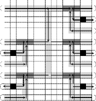
M1
central unit arrays are used for its routing, then eventually the remaining five unit arrays could be used (with an essential shift of each mixer) for their relevant tasks in parallel, where reagent (sample) droplets are dispensed from their own sources to the unit arrays and also mixed droplets are dis- posed after compulsory detections, all in parallel, as shown in Fig. 9. Due to space restraint, we depart almost all allied as- pects; a configured pin assignment in such a chip is directly shown in Fig. 10. Here the five mixers of size 1×3 each belong to the unit arrays 1, 2, and 4 (Ua1 , Ua2 , and Ua4 ) on the right part and the unit arrays 3 and 5 (Ua3 and Ua5 ) on the left part of the devised array, are as shown in the figure.
In very brief, according to Fig. 10, exactly eight pins (1 through 8; though only six pins are required in Ua1 ) help to route the reagent R up to the middlemost column of the given array, then it follows rectilinear routes for distributing succes- sive droplets of R to the five mixing regions belonging to five unit arrays. Particularly, one after the other two droplets of R
R
M3
S3
D3
Sink
S8
M5
S5
D5
Sink
S10
(a)
S1
D1
Sink
S6
M2
S2
D2
Sink
S7
S4
D4
Sink
S9
move up to pin 26 (in the middlemost column) for their own routes in Ua4 and Ua5 , and in a similar way, in succession two more droplets of R move up to pin 19 (in the same column) for their own routes in Ua2 and Ua3 , and a last droplet of R goes straight for mixing in Ua1 . In addition, for synchronous multi- ple operations, the pin configuration in a unit array on the left is obtained by making a mirror image of that in a unit array on the right (using exactly nine pins 31 through 39). The pins in the central unit arrays are configured for propagation of R as we desire them to move (using 24 pins, 7 through 30). Five distinct pins are used for holding reagents ready to enter into the mixers (pins 40 to 44).
The pins 36, 37, 32, 39, and 33 (second row below the detec- tion site) are used for routing the second set of five samples
Fig. 9. Layout of a modified droplet routing that uses five 1×3 mixers in an
18×15 array.
R 
 S1
S1

 Sink
Sink
 S6
S6
(S6 , S7 , S8 , S9 , and S10 ). After completion of the first set of as- say operations with five samples (S1 , S2 , S3 , S4 , and S5 ) and
one reagent, washing is necessary to avoid cross contamina-
tion. The second set of assay operations is performed in the
same way as done for the first set.
S3 
 S2
S2
S1 S2
S3 R
S4 S5
M1 M2
M3 M4 M5
D1 D2 D3 D4 D5


Sink

 Sink
Sink
M1 M2
M3 M4 M5
S8 
 S7
S7
S5 
 S4
S4
D1 D2 D3 D4 D5

(a)
S1 Si1 S2
R
Si2
S3 R
(b)
Si3 S4
Si4
S5 Si5
Sink 

S10 

 Sink
Sink
 S9
S9
M1 D1
S1 Si1
M2 D2
S2 Si2
M3 D3
S3 Si3
(c)
M4 D4
S4 Si4
M5 D5
S5 Si5
Fig. 10. Pin configuration in the 18×15 array that assigns same set of pins
33, 34, and 35 for each 1×3 mixing region and pin 39 for each detection site.
5.2. Multiple Assay Functions Attained in an 18×15 Ar- ray
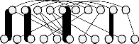
So, up to this point in time, the vividness of parallelism is not realized for a given restricted sized chip of capacity 18×15. Rather, we may observe that if the top-left unit array is used for dispensing droplets of a sample (reagent) and the three
Fig. 11. (a) The sequence graph of a representative bioassay, where rea-
gent R mixes disjointedly with each of the samples S 1 through S 5 in re- spective mixers M, and then the mixed droplets are sent for individual detection (D), all in parallel. (b) The placement graph of the assay, where the top row of circles indicates the operations (M and D) performed inside the array, and the bottom row of circles shows the sources (S and R) and sinks (Si) available outside the array. (c) The resultant placement graph after assigning the modules of the assay, which is free from any type of crossing.
Accordingly, a total of 44 pins are used to do all desired tasks of multiple bioassay operations in synchronism, and a very few unused spare cells are obtained that are not assigned
IJSER © 2015 http://www.ijser.org
International Journal of Scientific & Engineering Research, Volume 6, Issue 3, March-2015 753
ISSN 2229-5518
any pin; anyway, the blank rows of spare cells in Ua1 may be used as an alternative path for routing of R, if utmost neces- sary for any reason. This completes the pin assignment that we design for two sets, each having five multiple bioassay operations to be executed in parallel.
5.3. An Example Run for Several Bioassay Operations
An assay that performs two or more assignments for their exe- cution in parallel may enhance the efficiency of an array, for which a slightly modified array of size 18×15 is designed as shown in Fig. 11. Let us consider Case I in Section 1.2, where a reagent R is mixed in isolation with five different samples S1 through S5 ; the related sequence graph is shown in Fig. 11(a).
Now, till we do not know whether there is any overlapping of routing paths or risk of cross contamination among the droplets used herein. The routes of different droplets along with associated tasks are clearly shown in Fig. 11(b), which we call the placement graph. In this design, our objective is to realize an isomorphic representation of the placement graph
that contains no crossing of edges or less crossing as much as
only one source of reagent and reagent droplet is to be routed to all the unit arrays, it should be placed first and making this placement as a constraint, all the remaining ports and devices are then placed that results a placement graph as shown in Fig. 11(c), which is isomorphic to the placement graph shown in Fig. 11(b). The placement graph is same for the two phases of bioassay operations.
Here we have assumed a case where the same reagent droplet reaches to all the respective mixers where mixing is performed with different samples, the droplets must move mostly in parallel in the true sense, to complete the whole as- say. Here, as there is no crossing of edges in the placement graph, there is no need of scheduling of intra-washing during the assay is performed; rather, inter-washing is necessary to execute two parallel assays of ten assignments using the re- stricted sized biochip of capacity 18×15 with cross contamina- tion avoidance. Now, as per the scheduling of the said assay, the scheduling map obtained is shown in Fig. 12.
Clock pulses
we can. Here such a crossing indicates that the related drop- lets share at least a common cell (in different instant of time) that is to be washed in between to avoid cross contamination; otherwise, intra-assay washing is redundant.
for
k+9 k+12 k+15 k+18 k+21
S6 S7
S8 S9 S10
R For mixers
1
2
3
4
5
D1 D2
D3 D4 D5 Wd
Clock pulses
k+32

for
1
4
7
10
13
23
26
k+1 k+3 k+6
k+9
S1 S2
S3 S4 S5
R For mixers
1
2
3
4
5
D1 D2
D3 D4 D5 Wd
1
2
3
4
k+35
k′+1 1 k′1+3 2 k′1+6 3 k′+9 4 k′+12 5 k′+17
k′+21
k′+46
k+12
k+17 k+21 k+37
5 Fig. 13. The scheduling map for the sequence graph of the second phase,
which is very similar to the first phase of five assay operations, where
reagent R mixes separately with five samples S 6 −S 10 . Here m is the num- ber of clock pulses required for mixing and k′ = k+34+m−17 after which wash droplets are dispensed. Here at the (k′+23)rd clock pulse, the mixed
droplets are disposed from the array after detections are made at the
Fig. 12. The scheduling map for the sequence graph in Fig. 11(a), where reagent R mixes separately with five samples S 1 through S 5 . Here m is the number of clock pulses required for mixing and k = 25+m−17 after which wash droplets are dispensed. Here at the (k+23)rd clock pulse, the mixed droplets are disposed from the array after detections are made at the (k+21)st clock pulse in parallel. Next 14 clock pulses are needed for washing the whole array before starting a new assay for the second phase.
Here R represents the reagent, Si is the ith sample 1 ≤ i ≤ 10, Mi is the ith mixer, Di is the ith detection site, and Sii is the ith sink, 1 ≤ i ≤ 5. Naturally, there are one source of reagent and ten sources of sample(s), either same or different. So, there are
11 ports as sources of regular droplets and five sinks to dis- pose the mixed droplets after detection. Now to avoid cross contamination, i.e., to avoid crossing between the paths the devices can first be ordered in the following way. As there is
(k′+21)st clock pulse in parallel. Next 24 clock pulses are needed for washing the whole array before starting a new assay for a subsequent phase.
After completion of first five assay operations in a set we can perform another set of five assay operations. In this case we can perform all tasks of assays in two phases. In the first phase, we can use samples S1 −S5 to mix with R in isolation in a separate mixer, and then ports S6 −S10 are used as the sources of wash droplets for each respective unit array. During the second phase of assays, ports S6 −S10 are used for samples while ports S1 −S5 are used as wash droplet sources. Hence, Fig. 12 and Fig. 13 represent the first phase and the second phase of scheduling, respectively, for the 18×15 microfluidic biochip. Note that, next 24 clock pulses are required to wash the whole array before starting a new odd assay for a subse- quent phase of fresh operations.
IJSER © 2015 http://www.ijser.org
International Journal of Scientific & Engineering Research, Volume 6, Issue 3, March-2015 754
ISSN 2229-5518
5.4. Experimental Results
In this section, we compare the three biochips, two in existing articles [2, 5, 10, 14, 17] of size 15×15 and 10×10, and the third one that has been introduced in this paper, from their struc- tural and functional characteristics. The primary differences are: whether the bioassay operations are performed sequen- tially or in parallel, what are the sizes of mixers used, utiliza- tion of cells in the array, number of tasks carried out, number of assignments executed, etc. These are included in Table I and thus explained in brief as follows.
We may note that the foremost biochip is very much under- utilized as herein 33.78% cells are unused and [10] claims that it fails to use 6% cells of the 10×10 array, whereas this value is only 15.56% in designing such a large array. In our biochip we accomplish 900% more assignments by sacrificing only 76% more pins (over that required in the 15×15 array), where the mixer we introduce may operate in splitting-merging mode of operation and also in to-and-fro routing of mixed droplet. Here as the unit arrays are quite smaller in size, and the mixer and detection sites are much closer, the average routing time is greatly lesser in comparison to both the earlier two cases. Hence, the number of clock pulses we involve in performing two assays of ten assignments is 25+8+2×(m+d+w), which is comparable in contrast to its two earlier designs.
TABLE 1
A TABLE OF COMPARISON THAT ASSESSES TWO EXISTING ARRAYS
AND THE ARRAY INTRODUCED IN THIS PAPER OF SIZE 15×15 AND
10×10 EACH FROM THEIR PATTERN AND PRACTICAL VIEWPOINT.
HERE m, d, w, AND (w) ARE THE NUMBER OF CLOCK PULSES AP-
PLIED FOR MIXING, DETECTION, INTER-ASSAY WASHING, AND
INTRA-ASSAY WASHING, RESPECTIVELY.
Array size Features | 15×15 (Fig. 4) [5, 6, 14, 17] | 10×10 [10] | 18×15 (Fig. 9 and 10) |
Mode of operation | Sequential | Sequential | Parallel |
# of tasks | Six | Five | Eighteen |
# of mixers | One | One | Five |
Mixer size | 2×3 | 2×2 | 1×3 |
Pin count | 25 | 20 | 44 |
# of active cells | 58 | 48 | 105 |
# of guard cells | 91 | 46 | 123 |
# of unused cells | 76 | 6 | 42 |
Wash droplets | No | No | Yes |
# of clock pulses (for two assays) | 2 × (12 + 19 + m + d + w) | 2 × (8 + 5 + m + d + w) | 25 + 8 + 2 × (m + d + w) |
# of assignments | Two | Two | Ten |
In this design, pin 36 (below each mixer) is used as a deci- sion point, which is activated only when the mixing is en- sured, and pin 39 as detection site. We introduce intra-array wash droplets to wash the mixers and detection sites, only when the same reagent is used in a consequent assay opera- tion; otherwise, inter-assay washing is carried out, if the rea- gent is different.
6. CONCLUSION
Considering all functions, our design addresses very efficient- ly not only some specific field, but it covers many other do- mains as well. We would like to discuss some of them, in which our design or its extension as has been described above can handle the task very effectively.
In case of drug production, the produced drug must be tested before it is applied to some creature, rather testing should be done before revealing to the market. In our pro- posed design, these tests are especially simple and less time consuming. Generally, a drug should be mixed with blood, saliva, serum, etc. from human body for allergy testing. If all the mixings are performed in one chip in parallel, the testing becomes faster and less costly. So, at most six such reactions can be performed on an 18×15 chip using the scheduling de- vised in this paper, which is very much facilitating.
Again in case of drug manufacture, it is vital to test the drugs with different groups of blood whether there is any re- action between the different Rh factors. Using our chip we can also do the testing with multiple blood samples at a time, i.e., the whole procedure becomes faster.
In case of DNA analysis, though it is a fully sequential set
of reactions, i.e., DNA analysis is performed through some
assay operations which are interdependent. So, there is merely
any chance for incorporating parallelism. But using our chip
we can perform six such DNA analyses at a time. It has been
shown that we can perform one mixing in one of the mixers
and then a portion of the mixture is stored in the mixing re-
gion, and that can be used in some next phase of mixing. Thus,
a set of sequential operations can be performed in parallel on
an 18×15 array.
In a diagnostic centre, usually many people make a queue
for their respective tests. In that case, our solution strategy does all these in a much shorter period of time using only mi- cro-amount of samples. Also for the forensic department, our module is often capable to find out the truth of many enquir-
ies quickly.
Our module can be very useful for the department of agri-
culture, geology, anthropology, and other fields related to bi-
omedical, biochemical or natural sciences to find out the char-
acteristics of soil, water, and many more elements that are re-
lated to our health and farming.
In this paper, we have introduced a restricted sized biochip
with a capacity of 18×15 cells. In existing literature, similar
arrays of size 15×15 (or 10×10) is used only for one bioassay operation at a time as there is only one mixer of size 2×3 (or
2×2). This chip is underutilized, and the mode of operation is purely sequential up to this point in time. In all these respects, we have configured a pin assignment where five mixers of size 1×3 each have been introduced and hence the pin count is enhanced by 76% though a multiple assay operation with ten times gain in comparison to the primary assay is assured us- ing almost the same number of clock pulses as these assay operations are achieved in parallel.
Here in certain cases, only intra-assay washing is sufficient while doing successive multiple parallel assay operations and in these cases we may reduce the inter-assay washing time too before starting a new assay. Mixers we introduce are used for
IJSER © 2015 http://www.ijser.org
International Journal of Scientific & Engineering Research, Volume 6, Issue 3, March-2015 755
ISSN 2229-5518
to-and-fro mixing of mixed droplets or splitting-merging mode of operation. Here the pin configuration is so brilliant that the crossing of two different droplets does not arise, and hence the problem of cross contamination is eventually avoid- ed to achieve a novel design; additional cost and time for rout- ing wash droplets are abandoned.
REFERENCES
[1] http://www.tutorgig.com/encyclopedia
[2] Advanced Liquid Logic, http://www.liquid-logic.com
[3] K. F. Böhringer, “Towards optimal strategies for moving droplets in digital microfluidic systems,” ICRA, pp. 1468-1474, 2004.
[4] K. F. Böhringer, “Modelling and controlling parallel tasks in droplet based microfluidic systems,” TCAD, vol. 25, no. 2, pp. 329-238, 2006.
[5] K. Chakrabarty and F. Su, “Digital Microfluidic Biochips: Synthesis, Testing, and Reconfiguration Techniques,” CRC Press, 2007.
[6] K. Chakrabarty and T. Xu, “Digital Microfluidic Biochips Design
Automation and Optimization,” CRC Press, 2010.
[7] K. Chakrabarty, “Digital microfluidic biochips: A vision for function- al diversity and more than Moore,” VLSI Design, pp. 452-457, 2010.
[8] R. B. Fair, “Digital microfluidics: Is a true lab-on-a-chip possible?” Microfluid Nanofluid, Springer, vol. 3, pp. 245-281, 2007.
[9] M. R. Garey and D. S. Johnson, “A Guide to the Theory of NP- Completeness,” San Francisco, 1979.
[10] W. L. Hwang, F. Su, and K. Chakrabarty, “Automated design of pin- constrained digital microfluidic arrays for lab-on-a-chip applica- tions,” DAC, pp. 925-930, 2006.
[11] P. Paik, V. K. Pamula, and R. B. Fair, “Rapid droplet mixers for digital microfluidic systems,” Lab on a Chip, vol. 3, pp. 253-259, 2003.
[12] P. Paik, V. K. Pamula, M. G. Pollack, and R. B. Fair, “Electrowetting based droplet mixers for microfluidic systems,” Lab on a Chip, vol. 3, pp. 28-33, 2003.
[13] F. Su and K. Chakrabarty, “Architectural-level synthesis of digital microfluidics based biochips,” ICCAD, pp. 223-228, 2004.
[14] F. Su and K. Chakrabarty, “High-level synthesis of digital microfluid- ic biochips,” ICCAD, vol. 3, no. 4, Article 16, 2008.
[15] F. Su, W. Hwang, and K. Chakrabarty, “Droplet routing in the synthe- sis of digital microfluidic biochips,” DATE, pp. 323-328, 2006.
[16] V. Srinivasan, V. K. Pamula, M. G. Pollack, and R. B. Fair, “A digital microfluidic biosensor for multianalyte detection,” IEEE MEMS Con- ference, pp. 327-330, 2003.
[17] T. Xu and K. Chakrabarty, “Droplet-trace-based array partitioning and a pin assignment algorithm for the automated design of digital microfluidic biochips,” IEEE/ACM ICH/SCSS, pp. 112-117, 2006.
[18] T. Xu and K. Chakrabarty, “A cross-referencing based droplet manip- ulation method for high-throughput and pin-constrained digital mi- crofluidic arrays,” DATE, pp. 552-557, 2007.
[19] T. Xu and K. Chakrabarty, “Broadcast electrode-addressing for pin- constrained multifunctional digital microfluidic biochips,” DAC, pp.
173-178, 2008.
[20] T. Xu and K. Chakrabarty, “A droplet-manipulation method for ar- chiving high throughput in cross-referencing based digital microflu- idic biochips,” TCAD, vol. 27, pp. 1905-1917, 2008.
[21] T. Xu, W. L. Hwang, F. Su, and K. Chakrabarty, “Automated design of pin-constrained digital microfluidic biochips under droplet- interference constraints,” ACMJ ETCS, 2007, vol. 3, no. 3, Article 14,
2007.
[22] J. Zeng and T. Korsmeyer, “Principles of droplet electro-
hydrodynamics for lab-on-a-chip,” Lab on a Chip, vol. 4, pp. 265-277,
2004.
[23] M. R. Garey and D. S. Johnson, “A Guide to the Theory of NP- Completeness”, San Francisco, 1979.
[24] D. Dhal, P. Datta, A. Chakrabarty, and R. K. Pal, “Enhancement of Multiple Parallel Assay Operations with Cross Contamination Avoidance in a Given Biochip”, IEEE ICECS, Vol. 1, pp. 337-343,
2014.
IJSER © 2015 http://www.ijser.org