International Journal of Scientific & Engineering Research Volume 2, Issue 7, July-2011 1
ISSN 2229-5518
Fault Diagnosis and Condition Monitoring of
Machine-Structure by Signature Analysis
L. B. Bhuyar, S. V. Kshirsagar, G. K. Awari
Abstract— A novel fault diagnosis and condition monitoring method is developed for a cantilever beam type of machine structure. To avoid non-linearity, it is assumed that the crack is always open. Vibration parameters were obtained first from a simulation employing the Finite Element Method and then verified experimentally using Fast Fourier Transformer analyzer for different crack configurations. The unique relation between the vibration parameters and crack characteristics found was employed to solve the inverse problem by using Genetic Algorithm Optimization using elite strategy. The reliability and efficiency of this method is demonstrated using both numerical and experimental examples.
Index Terms— fault diagnosis, condition monitoring, genetic algorithm, crack detection, signature ananlysis
—————————— • ——————————
1 INTRODUCTION
iterature on fault detection and condition monitoring was focused on the vibration-based method which can be classified into modal-based and signature-
based methods. In modal based techniques data can be condensed from the actual measured quantities like reso- nant frequencies, mode shape vectors and quantities de- rived from these parameters for the crack detection [1, 3,
4, 6].
In signature based methods the vibration signature of
cracked machinery structure can be useful for the fault
diagnosis and condition monitoring. Thus, the develop-
ment of crack detection methods has received increasing
attention in recent years. Among these techniques, it is
believed that the monitoring of the global dynamics of a
structure offers favorable alternative if the on-line (in ser-
vice) damage detection is necessary. In order to identify structural damage by vibration monitoring, the study of the changes of the structural dynamic behavior due to cracks is required for developing the detection criterion.
[2, 5, 7-10].
1.1 Objectives
The work reported in this paper was on the numerical (finite element method) and experimental investigations of the effects of a crack on cantilever beam with one end fixed and one end free, with a view to detecting, quantify- ing and determining its extent and location. Harmonic and modal analysis were done in Ansys (12) aiming to find modal parameters. The results obtained by FEA si- mulation are validated with the experimental results. Thirteen number of steel cantilever beams were used for this experimental study. Cracks were introduced at dif- ferent locations from end, with crack depths ratio ranging from 0.l h to 0.9 h (h was the beam depth) in steps of 0.1, at each crack location. To extract natural frequencies from the change in dynamic parameter of the frequency re- sponse, sine sweep excitation was given at a point on the beam. Analysis is carried out in frequency domain for various crack scenarios. The forcing frequency has been
assumed to be controlling parameter and its influence on the response on the cracked beam studied with a broad range with respect to first three natural frequencies. Nat- ural frequencies being the global parameters of the beam, their shifts could be observed by using FRF measure- ments taken from virtually any point on the beam. In the same experimental set up impulse excitation tests were also carried out to verify the natural frequencies. The unique relation between the change in natural frequencies and crack characteristics found was employed to solve the inverse problem by using Genetic Algorithm Optimi- zation method. The results obtained were tabulated, plot- ted, and discussed.
In order to fulfill the development of a new fault diagno- sis and condition monitoring technique for a cantilever beam, the following specific tasks are required:
• Theoretical free and forced vibration analysis of the
cracked cantilever beam
• Simulation of the dynamic system and extraction of the
vibration parameters from a cracked and uncracked
beam by means of Finite Element method.
• Development of method to establish relationship of
vibration signals with crack positions and depths for
the theoretical and experimental data.
• Designing of Genetic Algorithm for condition monitor-
ing.
2 FINITE ELEMENT ANALYSIS
The cracked beam model having a transverse surface crack is generated in Ansys(12). For a crack depth and crack location the key points were first created and then line segments were formed. The lines were combined to create an area. Finally, this area was extruded and a three- dimensional triangular crack with a 1mm width on the top surface of the beam and a crack going through the depth of the beam model was obtained. An 8-node three- dimensional structural solid element under SOLID 45 was selected to model the beam. The beam was discretized
IJSER © 2011 http://www.ijser.org
International Journal of Scientific & Engineering Research Volume 2, Issue 7, July-2011 2
ISSN 2229-5518
into 11859 elements with 54475 nodes. Cantilever boun- dary conditions modeled by constraining all degrees of freedoms of the nodes located on the left end of the beam. APDL PROGRAMMING is used to create 135 cracked beam models by varying the crack depth from 5mm to 45 mm and crack location from 50 mm to 750mm.
3 EXPERIMENTAL SET-UP AND PROCEDURE
Table 1 gives the physical parameters used in the experi- ments. Thirteen beams were considered to obtain the vi- bration characteristics of the structure under different levels of damage. The measured vibration data is used in the subsequent chapters to demonstrate the applicability of the methods developed in this study.
Table 1.Parameters used in experiments.
Parameters Values Beam Length (L) 0.8 m
Beam Width (b) 0.006 m
Beam Height (h) 0.05 m
Modulus of Elasticity (E) 2.068x10¹¹ N/m2
Density of Beam Material (p) 7600.0 kg/m3
Excitation frequency 0 - 1.2 kHz

Poisson’s Ratio (!-) 0.33
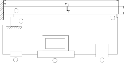
Fig. 1 shows the components in forced vibration analysis. Vibration signals were collected for both uncracked and cracked beam conditions. Beam clamped at one end, free at other end with a piezoelectric accelerometer [DYTRAN (USA)-3185 D] with magnetic base, mounted on the flat surface of beam attached with exciter at a point near to fixed end away from nodal point. A special fixture is manufactured for the attachment of beam with exciter to ensure a point contact. As an input beam was excited by a fast sine sweep signal generated by a function generator
L
C
a
1 h
3
2
6 5 4
1 : Beam
2 : Exciter
3 : Acclerometer
4 : FFT Analyser
5 : Computer Terminal
6 : Power Supply
Fig.1. Experimental Set-Up
which was then amplified and used to drive the exciter. FRF’s were measured for various fault conditions at the end point on the beam to include first three natural fre
quencies.
The sensor was connected to the signal-conditioning unit
(SVAN956 FFT analyzer), where the signal goes through a
charged amplifier and an analogue-to-digital converter
(ADC). The vibration signal in digital form was saved on
computer through a USB port for further analyses. The signal was then read from the memory and processed to extract the first few natural frequencies.
4 PROCEDURE
4.1 Fault Diagnosis Using Change in Natural
Frequencies
Once the changes in the natural frequencies of the beam are known crack depth and location can be found by plot- ting normalized frequency counter line. Using measure- ments based only on the two natural frequencies may not be sufficient to estimate a unique crack location, and crack depth for a beam with one crack, because more than one intersection point may be obtained. Consequently, the third natural frequency is also essential to obtain a unique value that indicates the exact crack location and crack depth.
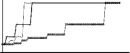
The contour lines with the values of 0.9805, 0.9559 and
0.9912 were plotted on the same axes as show in Fig. 2.
From the figure it could be observed that there are four
intersection points in the contour lines of the third and
the second mode. Consequently the contour of the first
mode is used to identify the crack location (C/L) = 7/16) and the crack depth ratio (a/h = 0.3), uniquely. The three contour lines gave just one common point of intersection, which indicates the crack location and the crack depth.
The contour lines obtained which indicates the crack Lo- cation (C/L) = 7/16) and the crack depth (a/h = 0.3), are shown in Fig. 2. This technique appeared to be good in identifying cracks in beams because a crack will definitely belong to a contour line for each mode, and measuring the lowest three natural frequencies in a beam is not a difficult task as long as measuring errors are reduced to a minimum or eliminated.
4.2 Condition Monitoring by Genetic Algorithm
To estimate the location and depth of a crack in a struc- ture using natural frequency information, we use genetic algorithm. The inputs to our crack detection system are three normalized natural frequencies ( L1m1 , L1m2 , L1m3 ). Identification of the crack location and depth is formu- lated as an optimization problem, and the genetic algo- rithm is used to find the optimal location and depth by maximizing the fitness function which is based on the difference of experimental and simulated frequencies. A three dimensional plot (search space); fitness value versus crack parameters (location and depth) is shown in Fig. 3. It shows that fitness value surface has many local maxima and there is a good chance of getting stuck in one of them. The goal is finding the exact parameters for which the
IJSER © 2011 http://www.ijser.org
International Journal of Scientific & Engineering Research Volume 2, Issue 7, July-2011 3
ISSN 2229-5518
Fig. 2. Crack identification technique by using frequen- cy contours of the first three modes of beam (1: mode 1, normalized frequency (0.9805); 2: mode 2, normalized frequency (0.9559); and 3: mode 3, normalized frequency (0.9912)).
Fig. 3. D surface of fitness function for the beam with crack parameters 0.3125 and 0.5.
fitness function value is one. Conventional optimization techniques have difficulty in finding the global maximum unless the starting point is in the immediate vicinity of it.
L1m
m - m

= e cracked uncracked = Normalized experimental
uncracked
Implementation
Problem encoding:
Bit strings used to encode the candidate solution, and the
representation of the solution or the approximation for
the true crack configuration is a bit string of which each
substring represents one parameter. The length of each
substring is determined by the solution accuracy and the
interval of the solution. In this problem, solution accura-
frequency.
DI values lie in the range 0 to 1, with 0 indicating exact match and 1 indicating no correlation between the pat- terns of the frequency changes.
To convert minimization problem into maximization problem, inverse function is used as a fitness function. The value of s, giving the highest fitness values, deter- mines the predicted damage location and size.
cies and the intervals for the crack location and crack depth are set to 0.0625 and 0.01 respectively and total string length of seven bits is used.
Fitness function = f (s) =
Genetic operators
1

1 + DI (s)
Initialization:
Initially an individual solution is randomly generated to
form an initial population.
Fitness evaluation:
Objective function used in the present paper is based on
the changes in experimental natural frequencies and si-
mulated natural frequencies. The change in natural fre-
quencies is termed as damage index. The form of objec-
tive function is based on the damage index (DI).
n

DI(s) =  L1m - L1me ( f (C / L, a / h))
i=1
Where

L1m = mcracked - muncracked = Normalized simulated
muncracked
frequency,
Following genetic operators were applied in genetic algo- rithm.
Selection:
The classical ‘roulette wheel’ method is implemented as a
selection criterion.
Crossover:
Crossover with a probability of (Pc) 0.6 was implemented
by choosing a point in the selected pair of strings and ex- changing the substrings defined by the cross over site.
Mutation:
The role of the ‘mutation’ operation is to introduce new
genetic materials (genes) to the chromosomes. With a
probability of (Pm) 0.05; an elite strategy was used thus
preventing the inadvertent loss of useful genetic material
in earlier phases of evolution.
Termination:
This generation process is repeated until a termination
condition has been reached. In the present study fixed
number of generations (100) reached was used as a termi-
IJSER © 2011 http://www.ijser.org
International Journal of Scientific & Engineering Research Volume 2, Issue 7, July-2011 4
ISSN 2229-5518
nation criterion.
Table 2 shows the results of genetic algorithm for four
different cracked beam configurations. It was found that,
population size of 30 requires less number of generations
to predict the crack parameters. Fig. 4 shows the conver-
gence pattern for a particular cracked beam configuration of 0.3125; 0.4.

Table 2. Results of the Genetic algorithm method under different population size.

No. Crack configuration Number of generations
frequencies of the vibrating beam are observed at the vicinity of crack location. When the crack location is constant but the crack depth increases, the natural fre- quency of the beam decreases.
• To identify the crack, contours of the normalized fre- quency in terms of the normalized crack depth and loca- tion are plotted. The intersection of contours with the constant damage index planes is used to relate the crack location and depth.
• The finite element formulation is performed using the

Location Ratio (C/l)
Depth Ratio (a/h)
Population
Ansys (12) environment and the modal natural frequen-
cies are calculated for comparison with the values ob- tained in the Experimental Analysis.
• The Genetic Algorithm approach has been successfully
1 0.0625 0.2
2 0.1875 0.4
3 0.3125 0.4
4 0.5 0.5

1
0 .98
0 .96
0 .94
adopted for condition monitoring cantilever beam, for the identification and localization of the crack with the help of modal natural frequencies.. Identification of the crack location and depth is formulated as an optimiza- tion problem, to find the optimal location and depth by maximizing the fitness function which is based on the difference of measured and calculated frequencies.
REFERENCES
[1] T.G.Chondros, A.D.Dimarogonas and J.Yao, A Continuous Cracked Beam Vibration Theory, Journal of Sound and Vibra- tion, 215(1), 1998, pp.17-34
0


Population size 10 Population size 20 Population size 30
Num ber of gene rations
Figure 4. Fitness value as a function of number of gen- erations.
5 CONCLUSION
In this study the use of change in dynamic response in fault diagnosis and condition monitoring has been inves- tigated. Based on results it is seen that presence of crack results in reduction in natural frequencies, also the change in frequencies is not only a function of crack depth and crack location, but also of the mode number. It could be stated that knowing the crack position could result in inaccurate prediction of its extent in a crack iden- tification problem by using only one mode. Otherwise, it becomes very difficult, as this could be misleading. Con- sequently viewing different modes separately is likely to indicate different crack depths, and crack positions. In general, the higher the number of modes used, the greater the degree of accuracy, and dependability of results. Following conclusions were made from the study:
• Theoretical analyses are performed for cantilever beam with transverse crack. Significant changes in natural
Beams using Changes in Frequencies and Amplitudes of Fre- quency Response Functions, Journal of Sound and Vibration,
265, 2003, pp.1-22
[4] Shuncong Zhong, S. Olutunde Oyadiji, Analytical Predictions of Natural Frequencies of Cracked Simply Supported Beams with a Stationary Roving Mass, Journal of Sound and Vibration,
311 ,2008, pp.328-352
[5] Jiawei Xiang, Yongteng Zhong, Xuefeng Chen, Zhengjia He, Crack Detection in a Shaft by Combination of Wavelet-Based Elements and Genetic Algorithm, International Journal of Sol- ids and Structures, 45, 2008, pp.4782-4795
[6] Marta B. Rosales , Carlos P. Filipich, Fernando S. Buezas, Crack
Detection in Beam-Like Structures, Engineering Structures, 31,
2009, pp.2257-2264
[7] R. K. C. Chan and T. C. Lai, Digital Simulation Transverse
Crack, Appl. Math. Modelling, 19,1995, pp.411-420
[8] Weixiang Sun, Jin Chen, Jiaqing Li, Decision Tree and PCA-
Based Fault Diagnosis of Rotating Machinery, Mechanical Sys- tems and Signal Processing, 21 ,2007, 1300-1317
[9] A.K.Darpe, K.Gupta, A.Chawla, Dynamics of a Bowed Rotor with a Transverse Surface Crack, Journal of Sound and Vibra- tion, 296, 2006, pp.888-907
[10] Ashish K. Darpe, A Novel Way to Detect Transverse Surface
Crack in a Rotating Shaft, Journal of Sound and Vibration, 305,
2007, pp.151-171
IJSER © 2011 http://www.ijser.org