International Journal of Scientific & Engineering Research Volume 2, Issue 10, October-2011 1
ISSN 2229-5518
Fault Modeling of Sequential Circuits at
Register Transfer Level
Suma M.S,K.S.Gurumurthy
Abstract— As the complexity of Very Large Scale Integration (VLSI) is growing, testing becomes tedious and tougher. As of now fault models are used to test digital circuits at the gate level or below that level. By using fault models at the lower levels, testing becomes cumbersome and will lead to delays in the design cycle. Thus there is a need to look for a new approach of testing the circuits at higher levels to speed up the design cycle. This paper proposes on Register Transfer Level (RTL) model- ing for digital circuits and computing the fault coverage. The result obtained through this work establishes that the fault cover- age with the RTL fault model is comparable to the gate level fault coverage.
Index Terms— fault coverage,fault list,fault models,fault simulation,RTL,stuck-at fault,test patterns.
—————————— ——————————
1 INTRODUCTION
VLSI industry is growing as per Moore’s law and integrated circuit designs are accordingly becoming more and more complex. As a result of this, VLSI testing has become expensive in terms of cost. Existing gate level fault simulation techniques exhibit poor performance standards when applied to such designs and are unsuit- able for early testability analysis or fault simulations. Also test generation and fault simulation efforts in the post synthesis phase do not contribute to the improve- ment in the design. Therefore a design methodology for fault simulation at higher levels of abstraction is highly desired.
Many high-level fault models and fault simulation techniques have been proposed. No single fault model is universally acceptable since no fault model has been de- veloped so far that comprehensively covers all classes of circuits. The RTL description is at a higher level of ab- straction and may not cover all the gate level faults [2].
The fault model proposed by F.Corno, G.Cumani,
M.Sonza Reorda and G.Squillero [2] adopts a particular
instantiation of the observability enhanced statement
coverage metric in addition to the single stuck-at bit
faults on all assignments targets of the executed state- ments. The model implies observability enhanced state- ment coverage by modeling one of the possible fault classes on executed statements. This is an incomplete modeling of the various faults associated with the RTL description of the circuit.
The fault model by Barry W. Johnson is developed via abstraction of industry standard single-stuck-line (SSL) faults into the behavioral domain. A functional analysis technique was used to evaluate the effects of the SSL faults on gate-level implementation. Since the gate-level netlist changes drastically during logic synthesis, the authors in [3] concluded that modeling all possible gate-
level faults at the RTL is highly inefficient.
The RTL fault model and simulation approach pro-
posed by Mao and Gulati [4] uses the single stuck-at fault
for each bit of all variables in the RTL model. The model
employs both the RTL description and functional verifi-
cation patterns. But their approach required one to run fault simulation twice, first in an optimistic mode and then in the pessimistic mode and to use the average of the results to reduce the difference between the RTL and the gate-level fault coverage. The experimental data shows as much as 10 % error between the actual gate- level fault coverage and the RTL fault coverage.
Another fault model proposed by Devadas and Ghosh
[5] is the Observability Enhanced Statement Coverage
Metric. This model requires that all statements in the
RTL description are executed at least once and that their effects are propagated to at least one primary output. As this approach can be fruitfully exploited for the test pat- tern for fault simulation, more accurate results are needed.
The fault model proposed by Karunaratne et al. [6]
does not consider stuck-at faults in the signal bit values and also not account for these faults. Also the process of locating the RTL faults and mapping them to the corres- ponding Gate-Level faults is to be done. It is therefore desirable to develop the fault model at a higher level of abstraction than the gate level. Fault Simulation and test- ing at the higher levels of abstraction have a better chance of being integrated well into the overall design process.
Jose M.Fernandes et al.[7] has proposed a new proba-
bilistic method for controllability evaluation based on a traitorously selection of registers to form groups. This work needs further optimization by computing the prob- abilistic impact of the simultaneous correction of differ- ent testability problems.
IJSER © 2011 http://www.ijser.org
International Journal of Scientific & Engineering Research Volume 2, Issue 10, October-2011 2
ISSN 2229-5518
The Unit II of the paper deals with the methodology, Unit III deals with the fault model and simulation Unit IV with results and finally Unit V with conclusion.
2 METHODOLOGY
In this work Verilog Hardware Description Language is used for writing the RTL models. The basic assump- tion is that the components are fault free and only their interconnections are affected. These map to the operators and variables in the RTL descriptions respectively. Gate level primitives can be instantiated in a model using gate instantiation as these are supported for synthesis. These primitive gates describe the hardware. Therefore synthe- sizing a gate primitive generates logic based on the gate behavior which eventually gets mapped to the target technology [1].Based on this the single stuck-at fault is modeled.The assumption is also that at most one fault occurs at a time in the circuit.
The proposed fault model is an improvement over the
model given by Karunaratne et al.[6].Stuck-at faults in
the signal bit values was not considered and accounted.
Also the process of locating the RTL faults and mapping them to the corresponding Gate-Level faults was not im- plemented.
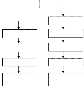
The analysis flow for the modeling approach is of two ways as shown in Fig. 1. One way targets on the gate-
level fault coverage while the other is on the RTL fault coverage. In the RTL path, the RTL design description is obtained based on the specification. Since the fault model is at the RTL, the fault is induced at the input and at the output. This is done by using a buffer for each bit in all of the variables in the RTL code. These buffers are inserted in the fault free circuit and should not disturb the func- tionality of the code. As a result, a modified faulty RTL circuit is obtained. To enable fault simulation the process of generating faulty circuits by inducing faults into the fault-free circuit is done. For each of the faults a new cir- cuit is created.
Testbench is developed and the simulation is first run
on a good circuit and then on each of the faulty circuits
using any simulator. The outputs obtained in each case
of the faulty circuits are compared with the output of the
good circuit to determine which faults are detected. That is the new faulty circuit and the fault free circuit is simu- lated and the outputs so obtained are compared. The fault list is tabulated. The ratio of the numbers of RTL faults detected to the total number of RTL faults gives the RTL fault coverage. For each RTL design descriptions gate level implementations are obtained for 65 nanome- ter target technology using logic synthesis tool and fault cover
age obtained by Tetramax tool. The fault list of both the
RTL as well as Gate-Level faults is compared. The ef- fectiveness of our fault model is determined by compar- ing RTL fault coverage with the fault coverage obtained at the gate level.
3 RTL FAULT MODEL AND SIMULATION
It is difficult to generate test for real defects due to the diversity of VLSI defects. For generating and evaluating a set of test patterns,fault models are needed. Widely a good fault model should almost give a true nature of the behavior of defects and it should also computationally work well in terms of fault simulation and test pattern generation. It is necessary to propose a fault model, that is a fault model for how faults occur and their impact on circuits and to do with the business of good and bad parts, many fault models have been proposed [4], but unfortunately, no single fault model accurately reflects the behaviour of all possible defects that can occur. As a result, a combination of different fault models at many instances are used in the generation and evaluation of test vectors and testing approaches developed for VLSI devices [2]. Developing a test for faults at higher level of abstraction and then determining the percentage of faults at the lower levels being covered is a good strategy. Fault models at higher levels result in significant savings in test cost and test time required for deriving tests.
The most common model used for logical fault is the
single stuck-at fault (SSF). In this a fault in a logic gate
gives a favourable outcome in one of its inputs or the output being fixed to either a logic 0(stuck-at-0) or a logic
1(stuck-at-1).
For our approach up-down counter is taken as an exam- ple.
module count_up_down #(parameter width
= 3)(
output reg [width:0] count,
output scanout,
input [width:0] data,
input load, Up, clear, clock
);
always@(posedge clock, negedge
clear)
if(!clear) count <=
{(width+1){1'b0}};
else if (load) count <= data;
else if (Up) count <= count +
1'b1;
else count <= count -
1'b1;
endmodule
IJSER © 2011 http://www.ijser.org
International Journal of Scientific & Engineering Research Volume 2, Issue 10, October-2011 3
ISSN 2229-5518
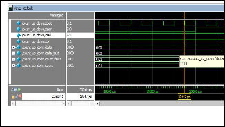
output stuck–at 0101 is as shown in Fig. 2
The above RTL design description is a fault free module. Faulty module is created such that the functio- nality will remain same as the fault free module .This is done by inserting the buffer for each of the ports. The faulty module appears as shown below.
module count_up_down #(parameter width
= 3)(
output [width:0] count,
input [width:0] data,
input load, Up, clear, clock );
reg [width:0] count_fault; wire [width:0] data_fault; wire
load_fault,clear_fault,clock_fault,Up_
fault;
buf L1(load_fault,load);
buf U1(Up_fault,Up);
buf C1(clear_fault,clear);
buf C2(clock_fault,clock);
buf D0(data_fault[0],data[0]); buf D1(data_fault[1],data[1]); buf D2(data_fault[2],data[2]); buf D3(data_fault[3],data[3]);
buf CT0(count[0],count_fault[0]);
buf CT1(count[1],count_fault[1]); buf CT2(count[2],count_fault[2]); buf CT3(count[3],count_fault[3]);
always@(posedge clock_fault, negedge clear_fault)
if(!clear_fault)
count_fault <=
{(width+1){1'b0}};
else if (load_fault)
count_fault <= data_fault;
else if (Up_fault)
count_fault <= count_fault +
1'b1;
else
count_fault <= count_fault - 1'b1;
endmodule
To these faulty and fault free modules fault simulation is performed with the reduced number of test patterns for each of the faults.The simulated waveform for the
Fig.2 Waveform for the output stuck-at 0101
4 RESULTS
At the writing of this paper, we have tested our approach on combinational logic circuits and sequential circuits. The results obtained by applying our approach to the RTL design descriptions and their corresponding Gate- level descriptions have been tabulated in table 1. At the gate-level, the gate-level netlist is created for each of the circuit used. Fault coverage is obtained for the scan in- serted gate-level netlists. From the results it can be ob- served that the RTL Fault Coverage obtained by the pro- posed fault modeling methodology has a close match to the Gate-level Fault Coverage for the tested digital cir- cuits.
TABLE 1
RTL VERSUS GATE-LEVEL FAULT COVERAGE
Name of the cir- cuit | RTL Fault Coverage | Gate-Level Fault Coverage |
JK flip-flop | 100% | 100% |
D flip-flop | 100% | 100% |
Updown counter | 100% | 100% |
Johnson counter | 100% | 100% |
5 CONCLUSION
With the progress of semiconductor technology testing of
VLSI circuits becomes more and more difficult and
at the same time cost is also increasing. Therefore it is important to achieve high fault efficiency with low cost. With this approach RTL designer can have an estimation of the achieved fault coverage before doing synthesis and also it is possible for the designer to locate faults at a higher level of abstraction. At present our approach is applied to combinational logic circuits and few sequen- tial logic circuits. In future we would like to extend the approach to complex sequential circuits such that there is a close match to the gate level fault coverage and hence reducing the impact on time to market.
IJSER © 2011 http://www.ijser.org
International Journal of Scientific & Engineering Research Volume 2, Issue 10, October-2011 4
ISSN 2229-5518
REFERENCES
[1] J.Bhaskar., “Verilog HDL Synthesis, A Practical Primer”, BSPublications,
2004.
[2] F.Corno,G.Cumani,M.Souxa Reorda,G.Squillero,:”An RT-level Fault
Model with High Gate Level Correlation”Proceedings of the IEEE Interna- tional High_Level Design Validation Test Workshop, 2000.
[3] Ronald J Hayne and Barry W.Johnson,”Behavioral Fault Modeling in a
VHDL Synthesis Environment”, IEEE VLSI Test Symposium, 1999.
[4] Weiwei Mao,Ravi K Gulati,”Improving Gate Level Fault Coverage by
RTL Fault Grading”, Proceedings of the International Test Conference, IEEE,
1996.
[5] Devadas,,A.Ghosh,K.Keuter”An Observability-Based Code Coverage
Metric for Functional Simulation”Proceedings of IEEE/ACM International
Conference on Computer Aided Design, 1996.
Design Requirements
Unmodified RTL Modified RTL Synthesis
[6] P.Goel,”Test Generation Cost Analysis and Projections,” Design Auto- mation Conference, 1980.
[7] Karunaratne,Sagahyroon,Prodhuturi,”RTL Fault Modeling”IEEE Cir- cuits and Systems August 2005.
[8] Jose M.Fernandes,Marcelino B.Santos,Arlindo L.Oliveira,Joao C.Teixeira,”IEEE International High Level Design and Test Workshop,2006. [9] Himanshu Bhatnagar,” Advanced ASIC Chip Synthesis “Kluwer Aca- demic Publishers, 2000.
[10] P.K.Lala ,”Digital Circuit Testing and Testability,“Academic Press,1997.
[11] L.T.Wang,C.W.Wu,X.Wen,”VLSI Test Principles and Architectures,
Pattern generation
Fault Simulation
RTL Fault Cov- erage
Scan Insertion
ATPG
Gate-level Fault
Coverage
“Morgan Kaufmann Publishers,2006. Fig. 1. Design flow with the proposed method
IJSER © 2011 http://www.ijser.org