International Journal of Scientific & Engineering Research, Volume 4, Issue 11, November-2013 339
ISSN 2229-5518
Fan Speed Control of Processor Based
On Environmental Temperature
1Adewale A. A., 2 Dike Ike, 3 Adelakun A. A.
1,2,3Department of Electrical and Information Engineering, Covenant University, Ota, Nigeria.
Abstract- Temperature is a physical property that is an essential part of life and Maintaining control of it is of paramount importance to man. Temperature is measured with various types of measuring instruments. But beyond the need to measure temperature, it must also be controlled and monitored. In an industrial setting with heavy equipment that need a round the clock cooling system so as to perform optimally without breakdown, it is important to have a mechanism that monitors the temperature situation, one that can detect the slightest threat to the condition of the systems as regards temperature change. Also temperature control can be used in personal computers to prevent overheating of the processor. This work involves sensing the temperature level of an environment and if a temperature out of range is detected, the fan speed increases to maximum. W hen the temperature drops below a threshold again, the fans are turned back off. The circuit is designed using a temperature sensor that is a thermistor. The temperature transducer is used to sense the temperature of the environment at that point in time and an indication shown on an LED.
Index Terms- LED, Overheating, Personal Computer, Sensor, Temperature, Thermistor, Transducer.
1 INTRODUCTION
Temperature control is the process through which temperature of an object is adjusted to achieve a desired temperature [1]. Test and measuring Instruments are indispensable in any electronics research, development or design environment. Test and measuring instruments can be categorized as digital and analog. Analog systems change their signal output linearly with the input and can be represented on a scale by means of a pointer. On the other hand, digital instruments or circuits represent their output as two discrete levels (‘1’ or ‘0’) and could show their output in a digital display either numerically or alphabetically. The early methods of temperature measurement were mostly by analogue means. This fact could be acknowledged from devices such as mercury - in-glass thermometers, thermocouples or thermopile instruments. There were issues that arose as a result of this. The components used to achieve this were affected easily by temperature fluctuations which created some measure of instability in them. For instance, considering the parameters of the various temperature transducers such as
thermocouples, resistance thermometers etc. It
can be seen that the most the components used in achieving it have their characteristic easily affected by the heat leading to poor precision and low reliability in the values being measured. When considering displays for the analogue systems precision in taking readings is also a problem due to issues in data storage for analogue systems and error due to parallax. Many techniques have been developed for measuring temperature, most of these functions by measuring some physical property of a working material that changes with temperature. One of the most popular devices for measuring temperature is the glass thermometer. It consists of a glass tube usually filled with mercury, which acts as the working fluid, an increase in temperature causes the fluid to expand, so that the temperature can be determined by measuring the volume of the fluid. Such thermometers are usually calibrated, so that one can read the temperature, simply by observing the level of the fluid in the thermometer. Other important devices for measuring temperature include: thermometer, thermistor, Resistance Temperature Detector, Pyrometers, Langmuir probes and other thermometers [2].
IJSER © 2013 http://w w w .ijser.org
International Journal of Scientific & Engineering Research, Volume 4, Issue 11, November-2013 340
ISSN 2229-5518
In this system, we will be using a thermistor to sense the temperature. By means of some integrated circuits, we would be able to transform the temperature sensed to a series of clocked pulses that would be counted, decoded then the value displayed by the dot LEDS.
2 MATERIALS AND METHODS
The operational process of the system involves monitoring the temperature in a room or computer system automatically (e.g. in a server room or in an industry) and automatically increasing the speed of the fan when the temperature is 40°C. The circuit is designed using a temperature sensor to sense the temperature at that instant; it will also show the ranges on an LED. The temperature sensor is used to sense the temperature and give a voltage output which is proportional to the
temperature for a range of 00C to 700C.
The voltage output is fed to the input of a voltage follower, which converts the voltage to frequency as part of an analogue to digital circuitry. The output is fed to a comparator and then through a mono-stable timers to sense the level of temperature at 40°C due to the design specifications.
2.1 Design Specification
The system built has the ability to sense and convert temperature with the help of a transducer which is an integrated circuit temperature sensor. An LM35 was used to get the desired result of increase in the speed of the fan and vice versa. This acts as feedback control. The system components are as shown
in Fig. 1.
Fig. 1. The System Components
The temperature controlled fan regulator is broken into four units as indicated in the block diagram above
- The DC power supply
- Temperature sensing unit
- The fan control unit
- LED display
All stages in the system use +5V DC power supply. The 220V AC power supply from PHCN was stepped down by the transformer to 12V RMS, after which a capacitor was used to filter the ripples from the transformer and then a 5V voltage regulator was used to regulate the voltage and keep it fixed at 5V. A power transistor was used to boost the 1.5mA current from the voltage regulator to 1A to power the circuit. The power supply circuit diagram is shown in Fig. 2.
IJSER © 2013 http://w w w .ijser.org
International Journal of Scientific & Engineering Research, Volume 4, Issue 11, November-2013 341
ISSN 2229-5518

+
AC N1,230V
N2, Vs
+
Load
range. Low cost is derived by trimming at the wafer level. The LM35's low output impedance and precise calibration make interfacing to output control circuitry conveniently easy. It can be used with single power supplies, or with plus
Voltage
source
50Hz
Power Transformer
DC and minus supplies as it draws only 60 µA from the supply , it has very low self-heating, less
than 0.1°C in still air. The LM35 is rated to operate over a -55° to +150°C temperature range, while the LM35C is rated for a -40° to+100 [3].
The LM3914 is a monolithic integrated circuit that senses analog voltage levels and powers 10
LEDs, providing a linear analog display. A single pin is used to change the display from a moving dot to a
bar graph. Current drive to the LEDs is programmable, thus eliminating the need for resistors. This feature allows operation of the whole system from less than 3V.
The simplified LM3914 circuit diagram is
Fig. 2. Power Supply Circuit Diagram
The temperature sensor used in our work is the LM35 sensor. The features of the LM35 sensor from the datasheet [13] are as follows:
- 0.5°C accuracy guarantee able (at +25°C)
- Rated for full -55° to +150°C range
- Suitable for remote applications
- Low cost due to wafer-level trimming
- Operates from 4 to 30 volts
- Less than 60 µA current drain
- Low self-heating, 0.08°C in still air
- Nonlinearity only ±¼°C typical
- Low impedance output, 0.1 Ohm for 1 mA load According to the information on the datasheet, each Celsius is 10mV. At 0 degrees Celsius, the analog voltage is 0V. The LM35 series are precision integrated-circuit temperature sensors, whose output voltage is proportional to the Celsius temperature. The LM35 thus has an advantage over other linear temperature sensors calibrated in Kelvin, as the user is not required to subtract a large constant voltage from its output to obtain convenient Centigrade scaling. The LM35 does not need any external calibration to provide typical accuracies of ±¼°C at room temperature and
±¾°C over a full -55 to +150°C temperature
shown in Fig. 3 to give the general idea of the circuit’s operation. A high input impedance buffer operates with signals from ground to 12V, and is protected against reverse and overvoltage signals. The signal is then applied to a series of 10 comparators; each of which is biased to a different comparison level by the resistor string. In the system, the resistor string is connected to an internal 1.25V reference voltage. Thus, for each 125mV that the input signal increases, a comparator will switch on another indicator LED. This resistor divider can be connected between any 2 voltages, providing that they are 1.5V below V+ and no less than V−. If an expanded scale meter display is desired, the total divider voltage can be as little as 200mV. Expanded-scale meter displays are more accurate and the segments light uniformly only if bar mode is used. At 50mV or more per step, dot mode is usable [4].
The current drawn out of the reference voltage pin, which is pin 7, determines the LED current. Approximately 10 times this current will be drawn through each lighted LED, with this current being relatively constant despite supply voltage and temperature variations. Current drawn by the internal 10-resistor divider, as well
as by the external current and voltage-setting
IJSER © 2013 http://w w w .ijser.org
International Journal of Scientific & Engineering Research, Volume 4, Issue 11, November-2013 342
ISSN 2229-5518
divider should be included in calculating LED
drive current.
The LM3914 is low-powered itself, and since many LEDs can be powered from about 3V, it is an efficient display driver. Typical standby supply current with all LEDs off is 1.6mA. However, any reference loading adds 4 times that current drain to the V+ (pin 3) supply input. For example, an LM3914 with a 1mA reference pin load (1.3k), would supply almost 10mA to every LED while drawing only 10mA from its V+ pin supply. At full-scale, the IC is typically drawing less than 10% of the current supplied to the display. The display driver does not have built-in hysteresis so that the display does not jump instantly from one LED to the next. Under rapidly changing signal conditions, this cuts down high frequency noise and often an annoying flicker. An “overlap” is built in so that at no time between segments are all LEDs completely OFF in the dot mode. Generally 1
LED fades in while the other fades out over a mV . The change may be much more rapid between LED No. 10 of one device and LED No.
1 of a second device joined to the first. The LM3914 features individually current regulated LED driver transistors. Further internal circuit components detects when any driver transistor goes into saturation, and prevents other circuit components from drawing excess current. These results in the ability of the LM3914 to drive and regulate LEDs powered from a pulsating DC power source. This ability to operate with fluctuating voltages also enables the display driver to interface with logic circuitry, optically-coupled solid-state relays, and low current incandescent lamps [5].
Fig. 3. LM3914 circuit diagram
3 RESULTS
The op-amp stage was tested on the breadboard before soldering. Most of the circuit testing was done by the simulator Proteus 7.4 but some aspect were not feasible with the simulator (like testing the LM35) since it can’t be simulated on this software. The system was tested by placing a sensor in hot or cold region to check the response of the fan in respect to cascade of the LEDs output which increase in bar when there is increase in temperature and vice versa. After carrying out all the paper design and analysis, the system was built and tested to ensure it’s working ability, and was finally constructed to meet the desired specifications. The implementation of this project was first done on a breadboard. A D.C power supply was first derived from a bench power supply in the electronics lab to test the circuit. Stage by stage testing was done according to the block representation on the breadboard, before soldering of circuit commenced on Vero board. The various circuits and stages were
soldered in tandem to meet desired workability
IJSER © 2013 http://w w w .ijser.org
International Journal of Scientific & Engineering Research, Volume 4, Issue 11, November-2013 343
ISSN 2229-5518
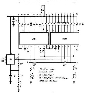

of the project. The system was coupled in a PVC plastic material. The final circuit diagram of the system is shown in Fig. 4, and the system prototype is shown in fig. 5.
Fig 5. System Prototype
4 CONCLUSION
Fig. 4. Comprehensive System Circuit
Diagram
The aim of this system is to design and construct a fan control system that will be able to determine the temperature of a processor or an environment and increase speed of the fan when the temperature is exceedingly high at about 400C. The system has achieved its main
objectives, which is an electric fan controlled by variation of temperature. This system can be used in an industry or commercial areas in the home or the concept could be applied to a personal computer to prevent overheating of the central processing unit. This system can also be adapted to operate with other domestic fans and blowers in industrial setting. The system can be redesigned in such a way that an infrared sensor is attached to the sensing circuit so as to detect the room occupants and turn the fan off or on
REFERENCES
[1] Leon brook, temperature control, 2009.
IJSER © 2013 http://w w w .ijser.org
International Journal of Scientific & Engineering Research, Volume 4, Issue 11, November-2013 344
ISSN 2229-5518
[2]en.wikipedia.org/wiki/Temperature_measurem ent
[3]www.redrok.com/TemperatureSensor_LM35_
10mVperC.pdf
[4]www.datasheetarchive.com/LM3915/Datashe et-051/DSA0026816.html
[5] www.ti.com/lit/ds/symlink/lm3914.pdf
IJSER © 2013 http://w w w .ijser.org