International Journal of Scientific & Engineering Research, Volume 6, Issue 5, May-2015 38
ISSN 2229-5518
Factors influencing surface integrity in hard machining of steels- A review
Balan Cristina- Iuliana
Abstract— During the last few years, hard machining has emerged as an attractive alternative to grinding, as it can be used for finishing steel components, in their hardened state (HRC 45 and above). Machining of hard steels, using advanced cutting tool materials, such as coated carbide, ceramic, CBN (cubic boron nitride) and PCBN (polycrystalline cubic boron nitride) inserts has a large number of advantages e.g. short cycle time, process flexibility, very good surface finish and higher removal rate, when compared to grinding or polishing. The present paper provides an overview of the main factors influencing surface integrity in hard machining of steel. There are many types of surface integrity (SI) problems reported in literature, among those being surface roughness, residual stresses, white layer and work hardening layers, as well as microstructural alterations. From the multitude of parameters influencing the SI of a hard machined component, cutting conditions, cutting tool characteristics, workpiece material properties, cutting fluid properties and machine tool rigidity appear to be the most important.
Index Terms— hard machining, influencing factors, surface integrity, hardened steel
—————————— ——————————
In broad terms, hard machining represents the machining of parts with a hardness of above 45 HRC although usually, in practice, it is used for harnesses of 58 to 68 HRC. The workpiece materials involved in this process include different types of hardened alloy steels, tool steels, case- hardened steels, hard- chrome coated steels, but also various super alloys, nitride irons and heat- treated metallurgical parts. Hard machining mainly represents a finishing or semi-finishing process that can result in high dimensional, form and surface finish accuracy [1]. Since its broader introduction in the mid-
1980s in the form of hard turning, this machining technology has evolved in various other operations such as milling, boring, broaching, hobbling etc. Due to the development of suitably rigid machine tools, superhard cutting tool materials, special toolholders and complete set-ups, hard machining has become accessible to any machine shop.
In the past, grinding used to represent the conventional solution to finishing hardened steel parts. Nowadays, there has been discovered a large number of benefits to machining this type of materials with cutting tools, which include the ease to adapt to complex part contours, high metal removal rates, low machine tool investment, environmentally friendly metal chips and the reduction or elimination of coolants, in most cases. It also has a series of disadvantages, concerning the higher tooling costs per unit, compared to grinding, the deterioration of surface finish with tool wear and the formation of white layer, which can delaminate and lead to the failure of the machined component [1].
The quality and performance of a product has a direct correlation to the surface integrity achieved by the final machining process. The SI of a machined component includes
————————————————
• Balan Cristina- Iuliana is currently pursuing doctorate degree program in industrial engineering in Faculty of Mechanical Engineering,
Mechatronics and Management, “Stefan cel Mare University of Suceava”, Suceava, Romania, PH-720229.
E-mail: cristina-iuliana.balan1988@gmail.com
the mechanical properties (residual stresses, hardness etc.), metallurgical states of the work material during machining (phase transformation, microstructure etc.) and topological parameters (surface roughness). The present paper offers a review of the most important factors that are found to influence the surface integrity of hardened steels, with reference to surface roughness, residual stresses and white layer formation.
It has been determined that, among the cutting parameters, the speed (v) and feed (f) have the biggest impact on the surface integrity of a hard machined component, while depth of cut only has a minor influence [2], [3], [4], [5], [6], [7], [8], [9], [10], [11], [12], [13]. Ibrahim Ciftici [2] and Ihsan Korkut [3] studied the influence of the cutting speed on the surface integrity of austenitic steels and determined that the surface roughness decreases as the speed increases. According to Jacobson et al. [12], when a bainitic steel is hard turned with PCBN tools, using cutting speeds between 50... 999 m/min, the best results are obtained when v= 170 m/min. Benga and Abrão [13] employed the RSM (Response Surface Methodology) for determining the optimum cutting parameters for hard turning the DIN 100Cr6 bearing steel (average hardness after treatment 62 HRC). The authors used four different cutting tool materials (mixed alumina, whisker reinforced alumina and two grades of PCBN) and obtained comparable surface roughness values in all four cases (lowest surface roughness value Ra = 0.25 μm). However, although the smallest feed always resulted in the best surface finish, the speed had a different impact. For mixed alumina and PCBN inserts the optimum cutting speed was v= 116… 130 m/min because for values below this limit the temperature rise was
IJSER © 2015 http://www.ijser.org
International Journal of Scientific & Engineering Research, Volume 6, Issue 5, May-2015 39
ISSN 2229-5518
insufficient to reduce the shear strength of the workpiece material and, consequently, the cutting forces, while values above this limit led to machine tool vibration, which could have had a detrimental effect on the surface finish. For the whisker reinforced cutting tools, the lowest cutting speed (v=
100 m/min) resulted in the best surface roughness, probably due to the rapid deterioration of the cutting edge when higher speeds were employed. Selvaraj and Chandramohan [14] studied the influence of the cutting parameters on the surface finish of the duplex stainless steels ASTM A 995 4A and ASTM A 995 5A, during dry turning with TiC (titanium carbide) and TiCN (titanium carbo-nitride) coated cemented carbide tools. For the experiments, the authors used five different cutting speeds (v= 80, 100, 120, 140, 160 m/min), three different feed rates (f= 0.04, 0.08, 0.12 mm/rev) and a constant depth of cut (d=
0.5 mm), and determined that the surface roughness decreases for speed values below 100 m/min and increases above this value. Hard turning test performed by Bosheh and Mativenga [15] on AISI H13 steel (54- 56 HRC), using PCBN cutting tools, showed that the hardness and depth of the white layer decreases as the cutting speed increases, due to a slight reduction in the workpiece temperature. According to Rech and Moisan [16] the residual stresses become more tensile as the cutting seed increases. Thamizhmanii et al. [17] determined that the optimum cutting parameters for hard turning AISI 440 C steels (45- 55 HRC) are v= 225 m/min, f=
0.125 mm/rev, d= 0.50 mm. Rech and Moisan [16] reported that the minimum feed for hard turning a 27MnCr5 cemented steel, average hardness 850 HV0.3 , should have values between
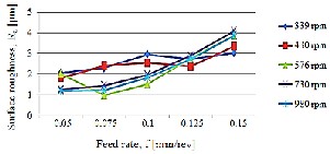
0.05- 0.1 mm/rev, to avoid side flow. According to Lim et al. [18], when hard turning AISI 4340 and AISI D2 steels the surface finish deteriorates as the cutting feed increases. This confirms the results obtained by Benga and Abrão [13] and Kumar et al. [19], who determined that in hard machining the smallest feed value usually corresponds to the best surface roughness (Fig. 1).
Fig.1. Influence of feed rate on the surface roughness of the EN 47 steel
[19]
Regarding the depth of cut, various studies have shown that this parameter does not have a significant impact on surface roughness [9], [11], [18], [20], [21], [22]. According to Huiping el al. [23], depth of cut has a certain influence on the residual stress state, but this influence is so complex that it has yet to be determined.
According to [24], when the side and end cutting edge angles (k & k’) are increased, the surface finish of a machined component worsens.
On the other hand, large nose radius (rε ) cutting tools result in very smooth surfaces, for low feed rates and high cutting speeds. Fang [25] studied the influence of the nose radius on the residual stress distribution when hard turning the JIS SUJ2 bearing steel. The author used three grades of CBN tools, with three different nose radiuses (rε = 0.4, 0.8, 1.2 mm) and discovered that the compressive residual stresses on the machined surface tend to become more tensile as the nose radius increases. Chou and Song [26] performed hard turning test on AISI 52100 bearing steel and reported that the best surface roughness value corresponded to the largest nose radius employed. For new cutting tool, the author determined that the white layer appears only for high feed rates (f= 0,3 mm/rev), and that small nose radius tools result in deeper layers. If the cutting tool is worn, the white layer can be observed even for low feed rates (f= 0.05 mm/ rev) but, in this case, large nose radiuses result in deeper white layers.
The rake angle (γ) influences the capability of a tool to cut the workpiece material and to form the chip. When hard materials are machined, the rake angle should be small, or even negative, when carbide, PCBN or diamond cutting tools are employed. The harder the workpiece material is, the smaller should the rake angle be. Jacobson [27] hard turned M50 steel samples (61 HRC after heat treatment) and determined that a large rake angle combined with a small nose radius generates a compressive residual stress profile. According to Dahlman et al. [28], who studied the influence of the rake angle, cutting speed and feed on the surface integrity of an AISI 52100 bearing steel in hard turning with CBN tools, the surface residual stress are tensile regardless of the rake angle value. On the other hand, at a depth of 5- 10 μm below the surface, the residual stress profile was compressive. For rake angles as small as γ= -41°, the authors noticed a significant increase in the magnitude of the compressive residual stresses. Thus, they concluded that a large negative value of the rake angle results in large compressive residual stresses. Singh and Venkateswara [29] investigated the effect of the cutting parameters and cutting tool geometry on the surface roughness of the AISI 52100 bearing steel (58± 2 HRC). Although they determined that the main influencing factor is the feed rate, the interaction between the rake angle and the nose radius presents a significant impact: as the rake angle increases, so does the surface roughness and small nose radiuses induce large surface roughness values.
According to [30],[31], [32] an increase in the relief angle (α) results in a deterioration of the surface finish, due to an increased radial ware of the cutting tool.
Concerning the inclination angle of the cutting edge (λ), literature shows that surface finish is better when larger values are employed [33], [34], [35].
Abrăo et al. [36] studied the influence of the cutting tool material (PCBN with low and high CBN content, mixed alumina, whisker reinforced alumina and silicon- nitride based) when finish turning AISI H13 hot work die steel (52
IJSER © 2015 http://www.ijser.org
International Journal of Scientific & Engineering Research, Volume 6, Issue 5, May-2015 40
ISSN 2229-5518
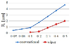
HRC) and AISI 52100 bearing steel (62 HRC). The authors determined that the best surface roughness values can be obtained for the low content CBN and the mixed alumina cutting tools (Ra values as low as 0.14 μm). However this value corresponded to the highest cutting speed (v= 200 m/min), for the tool steel, and the lowest cutting speed for the bearing steel. Davim et al. [37] and Gaitonde et al. [38] compared the performance of mixed alumina cutting tools with wiper and conventional geometry, used for turning hardened AISI D2 cold work steel (62 HRC). The authors reported that the use of the wiper geometry cutting tools resulted in a better surface finish, despite of the higher cutting forces reported for the conventional geometry tool. These results were confirmed by Samardžiova and Neslušan [39] who determined that the surface roughness can be reduced by half if a wiper geometry cutting tool is employed (Fig. 2).
Fig.2. Influence of cutting edge geometry on surface roughness [39]
Varela et al. [40] studied the influence of the cutting edge preparation on the residual stress distribution, when hard turning a 300M steel (hardened to 52 HRC). For their experiments, the authors used ceramic inserts with three different cutting edge preparations (chamfer, hone + chamfer and hone) and determined that the hone + chamfer cutting edge results in larger compressive stresses (peak value of
358.28 MPa), compared with the hone and chamfer edges (Fig.
3).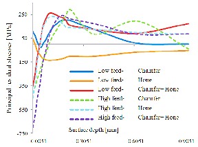
Fig.3. Influence of cutting edge preparation on residual stresses [40]
The chamfer edge generated a largely tensile residual stress profile, with a peak residual stress of 202.5 MPa. On the other hand, the hone edge induced a tensile surface residual stress of 47 MPa, while the residual stress profile was predominantly compressive. Regarding the surface roughness, in this case, the best results were obtained for the chamfer cutting edge preparation, followed by hone and, lastly, hone+ chamfer.
A large number of studies have shown that an increase in the workpiece material hardness results in an improvement in surface finish (similar cutting conditions) [6], [30], [41], [42], [43], [44], [45], [46], [47], [48] (Fig. 4).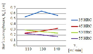
Fig.4. Influence of workpiece material hardness on surface roughness [30]
Chavoshi and Tajdari [49] studied the influence of the material hardness and spindle speed on the surface finish of the AISI 4140, using CBN cutting tools. The authors determined that the surface roughness decreases for hardness values up to 55 HRC and increases above this value (Fig. 5).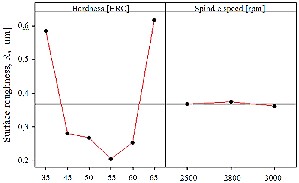
Fig.5. Influence of workpiece material hardness and spindle speed on surface roughness [49]
The authors obtained the following results:
• for a workpiece hardness of 35 HRC, the best surface roughness value was Ra = 0,537 µm, for a spindle speed of 2500 rpm;
• for a workpiece hardness of 45 HRC, the best surface roughness value was Ra = 0,24 µm, for a spindle speed of 2500 rpm;
• for a workpiece hardness of 55 HRC, the best surface roughness value was Ra = 0,175 µm, for a spindle speed of 3000 rpm;
IJSER © 2015 http://www.ijser.org
International Journal of Scientific & Engineering Research, Volume 6, Issue 5, May-2015 41
ISSN 2229-5518
• for a workpiece hardness of 60 HRC, the best surface roughness value was Ra = 0,222 µm, for a spindle speed of 3000 rpm;
• for a workpiece hardness of 65 HRC, the best surface roughness value was Ra = 0,544 µm, for a spindle speed of 2800 rpm;
It is obvious that the best surface roughness value corresponds to a workpiece hardness of 55 HRC, regardless of the spindle speed. All in all, for workpiece material harness between 35- 55 HRC, the surface roughness follows a descending trend.
Nowadays, most experimental studies focus on dry machining or near dry machining (MQL), as they offer a large array of benefits [50], [51]. MQL (minimum quantity lubricant) refers to the use of cutting fluids in minuscule quantities, usually between 50- 500 ml/h. Hamdan et al. [50] studied the performance of three different cutting fluids in hard machining, using a pulsing jet MQL system. The selected cutting fluids were pure oil (FUCHS SSN 321 PF), soluble oil (ECOCOOL 62101T) and semi-synthetic cutting fluid (ECOCOOL 68 CF2). The authors discovered that, for the pure oil and the semi-synthetic cutting fluid, the average surface roughness decreases with the increase of speed. On the other hand, when soluble oil was used, the surface roughness showed a slight increase with the speed. Thus, when a smooth surface finish is desired, it is best to use pure oil or semi- synthetic cutting fluid. Oliveira et al. [51] studied the effect of the minimal quantity lubricant on the surface roughness, tool life and tool wear, of a high speed milled AISI H13 hardened steel. The authors determined that the use of MQL not only shortens the tool life with up to 37,2%, but also promotes the appearance and spread of thermal cracks on the cutting edge, when compared with dry cutting. Regarding the surface roughness, no differences were noted between the use of MQL and dry machining. Leppert [52] compared the surface roughness obtained through high speed milling of a hardened 18G2A steel (50 HRC), using three different cutting environments: air, minimum quantity lubricant (MQL) and emulsion. For low cutting feeds (f= 0.08 mm/rev.), it was determined that the influence of the cutting fluid is limited: dry machining resulted in a slight decrease of Ra , compared with the use of emulsion, while MQL registered the best results (Ra = 0.37 µm). By increasing the feed, these differences became more notable, and MQL continued to offer the best results. This study confirms the results obtained by Thepsonthi et al. [53], who studied the influence of the MQL use (2 ml/ min rate, pulsing jet) in the high speed milling of a hardened steel (51 HRC) and determined that this method shows superior results in terms of surface roughness, tool wear and tool life, compared to dry machining and machining with flood application, especially in the high speed domain. Avila et al. [54] analyzed the performance of different cutting fluids during the hard turning of the AISI 430 steel, hardened to 49 HRC, with mixed alumina tools. Their results showed that when the workpiece surface is finished with a high cutting speed (v= 300 and v= 400 m/ min), the use of cutting
fluid results in a better surface roughness. Generally, the use of emulsion offered a better surface finish than synthetic cutting fluids. In certain conditions, the latter showed poorer results than even dry machining.
According to [55], [56], [57] one of the main factors that influence the quality of a machined surface is the radial run- out of the cutting tool, caused either by the tilt of its axis, or by its displacement in relation with spindle’s axis. This is especially notable where high rotational speeds are concerned, as they tend to induce large centrifugal forces that multiply the radial run- out of the cutting tool.
The present paper represents a review of the results obtained by various authors that have analysed the influence of different factors on the surface integrity of hard machined steels. The surface integrity characteristics that have been discussed are surface roughness, residual stresses and white layer. Among the many influencing factors, the most important, according to the published literature, proved to be the cutting parameters (speed and feed), the cutting tool characteristics (geometry, edge preparation, material), workpiece material properties (hardness), cutting fluid and machine tool rigidity.
This paper has been financially supported within the project entitled „SOCERT. Knowledge society, dynamism through research”, contract number POSDRU/159/1.5/S/132406. This project is co-financed by European Social Fund through Sectorial Operational Programme for Human Resources Development 2007-2013. Investing in people!
[1] J. Davim, “Machining of Hard Materials”, Springer London, pp. 1-3, 2011.
[2] I. Ciftci, „Machining of Austenitic Stainless Steels Using CVD Multi- Layer Coated Cemented Carbide Tools”, Tribology International, Vol.
39, No. 6, pp. 565-569, 2006.
[3] I. Korkut, M. Kasap, I. Ciftci and U. Sekar, “Determination of
Optimum Cutting Parameters during Machining of AISI 304
Austenitic Stainless Steel”, Materials & Design, Vol. 25, No. 4, pp. 303-
305, 2004.
[4] X.L. Liu, D.H. Wen, Z.J. Li, L. Xiao and F.G. Yan, “Experimental study on hard turning hardened GCr15 steel with PCBN tool”, Journal of Materials Processing Technology 129, pp. 217- 221, 2002.
[5] D.I. Lalwani, N.K. Mehta and P.K. Jain, “Experimental investigations
of cutting parameters influence on cuttin forces and surface finish hard turning of MDN250 Steel”, Journal of Materials Processing Technology 206, pp. 167- 179, 2008.
[6] T. Ozel, T.-K. Hsu and E. Zeren, “Effects of cutting edge geometry, workpiece hardness, feed rate and cutting speed on surface roughness and forces in finish turning of hardened AISI H13 steel,
IJSER © 2015 http://www.ijser.org
International Journal of Scientific & Engineering Research, Volume 6, Issue 5, May-2015 42
ISSN 2229-5518
Springer London, 2003.
[7] T. Ozel , T.-K. Hsu and E. Zeren, “Effects of cutting edge geometry, workpiece hardness, feed rate and cutting speed on surface roughness and forces in finish turning of hardened AISI H13 steel, International Journal of Advanced Manufacturing and Technology 25, pp.
262- 269, 2005.
[8] L. Chen, “Study on prediction of surface quality in machining process”, Journal of Materials Processing Technology 205, pp. 439-450,
2008.
[9] S.P. Dilbag and R. Venkateswara, “A surface roughness prediction model for hard turning process”, International Journal of Machine Tools and Manufacture 32, pp. 1115–1124, 2007.
[10] K. Bouacha, M.A. Yallese, T. Mabrouki and J.F Rigal, “Statistical analysis of surface roughness and cutting forces using response surface methodology in hard turning of AISI 52100 bearing steel with CBN tool”, International Journal of Refractory Metals & Hard Materials
28, pp. 349-361, 2010.
[11] H. Aouici, M.A. Yallese, A. Belbah and M.F. Ameur, “Experimental investigation of cutting parameters influence on surface roughness and cutting forces in hard turning of X38CrMoV5-1 with CBN tool”, Sadhana, Vol. 38, Part 3, pp. 429- 445, June 2013.
[12] M. Jacobson, P. Dahlman and F. Gunnberg “Cutting speed influence on surface integrity of hard turned bainite steel”, Journal of Materials Processing Technology 128, pp. 318–323, 2002.
[13] G.C. Benga and A.M. Abrao, “Turning of hardened 100Cr6 bearing steel with ceramic and PCBN cutting tools, Journal of Materials Processing Technology, Vol. 143- 144, pp. 143- 144, 237– 241, 2003.
[14] P. Selvarajan and P. Chandramohan, “Influence of Cutting Speed, Feed Rate and Bulk Texture on the Surface Finish of Nitrogen Alloyed Duplex Stainless Steels during Dry Turning”, Engineering, Vol. 2, pp. 453- 460, 2010.
[15] S.S. Bosheh and P.T. Mativenga, “White layer formation in hard
turning of H13 tool steel at high cutting speeds using CBN”,
International Journal of Machine Tools and Manufacture, Vol. 46(2), pp.
225–233, 2006.
[16] J. Rech, and A. Moisan, ISurface integrity in finish hard turning of case-hardened steelsI, International Journal of Machine Tools and Manufacture, Vol. 43(5), pp. 543–550, 2003.
[17] S. Thamizhmanii, B. Bin Omar, S. Saparudin and S. Hasan, “Surface roughness analyses on hard martensitic stainless steel by turning, Journal of Achivements in Materials an Manufacturing Engeneering, Vol.
26 (2), pp. 139- 141, 2008.
[18] J.G. Lima, R.F. Ávila, A.M. Abrão, M. Faustino and J.P. Davim, “Hard turning: AISI 4340 high strength low steel and AISI D2 cold work tool steel”, Journal of Materials Processing Technology, Vol. 169, pp. 388–395, 2005.
[19] A. Kumar and M.K. Paswan, “Optimization of Surface Topography for Hard Material Machining With CNC End Milling”, International Journal of Innovative Research in Science, Engineering and Technology, Vol. 3, Issue 1, pp. 8889- 8896, 2014.
[20] Y. Sahin and A.R. Motorcu “Surface roughness model for machining mild steel with coated carbide tool”, Materials & Design, Vol. 26, pp.
321–326, 2005.
[21] D. Xuan-Truong and T. Minh-Duc “Effect of cutting conditions on tool wear and surface roughness during machining of Inconel”, International Journal of Advanced Engineering Technology, pp. 108-112,
2013.
[22] C.X. Feng, “An experimental study of the impact of turning
parameters on surface roughness”, Proceedings of the Industrial
Engineering Research Conference, 2036, 2001.
[23] Z. Huiping, Z. Hong and L. Yinan, “ Surface Roughness and Residual Stresses of High Speed Turning 300M Ultrahigh Strength Steel”, Hindawi Publishing Corporation, Advances in Mechanical Engineering, Volume 2014, Article ID 859207, 2014.
[24] M. Groover, “Fundamentals of Modern Manufacturing, Materials, Processes snd Systems”, John Wiley and Sons (Asia), Student Edition,
2007.
[25] N. Fang, “ Slip-line modeling of machining with a rounded-edge tool
– part I: new model and theory”, Journal of the mechanics and physics of solids, Vol. 51, pp.715-742, 2003.
[26] K. Chou and H. Song, “Tool nose radius effects on finish hard turning”, Journal of Materials Processing Technology, Vol. 148, pp. 259-
268, 2004.
[27] M. Jacobson, “ Surface Integrity of Hard-Turned M50 Steel, Proceedings of the Institution of Mechanical Engineers”, Part B: Journal of Engineering Manufacture, Vol. 216, No.1, pp. 47-54, 2002.
[28] P. Dahlman, F. Gunnberg and M. Jacobson, “The influence of rake angle, cutting feed and cutting depth on residual stresses in hard turning”, Journal of Materials Processing Technology, Vol. 147, pp.181-
184, 2004.
[29] D. Singh and R. Venkateswara, “A surface roughness prediction model for hard turning process”, International Journal of Advanced Manufacturing and Technology, Vol. 32, pp. 1115- 1124, 2007.
[30] A. Luca, “Metode de evaluare a rugozităţii suprafeţelor aşchiate cu
scule metalice”, Polithnium Iasi, ISBN: 978-973-621-408-0.
[31] U. Persson, “ Surface roughness measurement on machined surfaces using angular speckle correlation”, Journal of Materials Processing Technology, pp. 233- 238, 2006.
[32] V. Savas and C. Ozay, “Analysis of the surface roughness of tangential turn-milling for machining with end milling cutter”, Journal of Materials Processing Technology, pp. 279- 283, 2007.
[33] U.A. Dabade, S.S. Joshi and N. Ramakrishnan, “Analysis of surface roughness and chip cross-sectional area while machining with selfpropelled round inserts milling cutter”, Journal of Materials Processing Technology, Vol. 132, (1– 3), pp. 305–312, 2003.
[34] X. Chen, J. Zhao, Y. Dond, S. Han and A. Li, “Effects of inclination angles on geometrical features of machined surface in five-axis milling”, International Journal of Advanced Manufacturing and Technology, Vol. 65, pp. 1721–1733, 2012.
[35] Y. Quinsat, L. Sabourin and C. Lartigue, “Surface topography in ball-
end milling process: description of a 3D surface roughness parameter”, Journal of Materials Processing Technology, Vol. 195(1–3), pp. 135–143, 2008.
[36] A.M. Abrăo, D.K. Aspinwall and M.H.L. Wise, “Tool life and workpiece surface integrity evaluations when machining hardened AISI H13 and AISI E52100 steels with conventional ceramic and PCBN tool materials”, SME technical paper, Society of Manufacturing Engineers MR95-159, Dearborn, MI, pp. 1–7, 1995.
[37] J.P. Davim and L. Figueira, ”Comparative evaluation of conventional
and wiper ceramic tools on cutting forces, surface roughness, and tool wear in hard turning AISI D2 steel”, Proceedings of the Institution of Mechanical Engineers, Vol. 221, pp. 625–633, 2007.
[38] V.N. Gaitonde, S.R. Karnik, L. Figueira and J.P. Davim, “ Machinability investigations in hard turning of AISI D2 cold work tool steel with conventional and wiper ceramic inserts”, International
Journal of Refractory Metals & Hard Materials, Vol. 27, pp. 754– 763,
IJSER © 2015 http://www.ijser.org
International Journal of Scientific & Engineering Research, Volume 6, Issue 5, May-2015 43
ISSN 2229-5518
2009a.
[39] M. Samardžiova and M. Neslušan, “ Development of surface roughness in hard turning of 100 Cr6 using mixed ceramic cutting tool with wiper geometry an conventional geometry”, Research Paper, Faculty of Materials Science and technology in Trnava, Slaovak University of Technology in Bratislava, pp. 193- 197, 2013.
[40] P.I. Varela, C.S. Rakurty and A.K. Balaji, “Surface Integrity in Hard Machining of 300M Steel: Effect of Cutting-Edge Geometry on Machining Induced Residual Stresses, Procedia CIRP 13, pp. 288 – 293,
2014.
[41] H. Aouici, M.A. Yallese, K. Chaoui and T. Mabrouki, “Analysis of surface roughness and cutting force components in hard turning with CBN tool: Prediction model and cutting conditions optimization”, Measurement, Vol. 45, pp. 344– 353, 2012.
[42] E.D. Derakhshan and A.A. Akbari, “Experimental Investigation on the Effect of Workpiece Hardness and Cutting Speed on Surface Roughness in Hard Turning With CBN Tools”, Proceedings of the World Congress on Engineering, Vol II, WCE 2009, July 1 - 3, 2009, London, U.K.
[43] T. Ozel , T.K. Hsu and E. Zeren, “Effects of cutting edge geometry,
workpiece hardness, feed rate and cutting speed on surface roughness and forces in finish turning of hardened AISI H13 steel”, International Journal of Advanced Manufacturing and Technolog, Vol.
25, pp. 262–269, 2005.
[44] Y. Matsumoto, F. Hashimoto and G. Lahoti, “ Surface integrity generated by precision hard turning”, Annals of CIRP, Vol. 48(1), pp.
59–62, 1999.
[45] J.D. Thiele and S.N. Melkote, “Effect of cutting edge geometry and workpiece hardness on surface generation in the finish hard turning of AISI 52100 steel”, Journal of Materials Processing Technology, Vol. 94, pp. 216–226, 1999.
[46] J.D. Thiele, S.N. Melkote and R.A. Peascoe, “Effect of cutting-edge
geometry and workpiece hardness on surface residual stresses in finish hard turning of AISI 52100 steel”, ASME Journal of Manufacturing Science and Engineering, Vol. 122, pp. 642–649, 2000.
[47] Y.B. Guo and C.R Liu, “Mechanical properties of hardened AISI
52100 steel in hard machining processes”, ASME Journal of
Manufacturing Science and Engineering, Vol. 124, pp. 1–9, 2000.
[48] Y.K. Chou, C.J. Evans and M.M. Barash, “Experimental investigation on CBN turning of AISI 52100 steel”, Journal of Materials Processing Technology, Vol. 134, pp. 1–9, 2002.
[49] M. Tajdari and S.Z. Chavoshi, “Surface roughness modelling in hard turning operation of AISI 4140 using CBN cutting tool”, International Journal of Materials, Form 3, pp. 233–239, 2010.
[50] A. Hamdan, M. Fadzil, K.A. Abou-El-Hossein and M. Hamdi, “Performance evaluation of different types of cutting fluid in the machining of AISI 01 hardened steel using pulsed jet minimal quantity lubrication system”, Journal of Aerospace Engineering, pp. 1-9,
2013.
[51] A.J. Oliveira, “Effect of minimal quantity lubricant (MQL) in high speed milling of AISI H13 hardened steel with carbide”, Proceedings of COBEM, 2009.
[52] T. Leppert, „Influence of cooling and lubrication on selected features of geometrical structure of surfaces turned at high cutting speeds”, Journal of Polish CIMAC, Vol. 7, Nr. 3, pp. 121- 126, 2012.
[53] T. Thepsonthi, M. Hamdi and K. Mitsui, “Investigation into minimal-
cutting-fluid application in high-speed milling of hardened steel using carbide mills”, International Journal of Machine Tools and
Manufacture, Vol.49, No. 1,pp. 156-162, 2009.
[54] R.F. Ávila, A.M. and Abrăo, A.M., “The effect of cutting fluids on the machining of hardened AISI 4340 steel”, Journal of Materials Processing Technology , Vol. 119, pp. 21–26, 2001..
[55] S. Wojciechowski and P. Twardowski, “Tool life and process dynamics in high speed ball end milling of hardened steel”, Procedia CIRP 1, pp. 289–294, 2012.
[56] O.E.E.K. Omar, T. El-Wardany, E. Ng and M.A. Elbestawi, “An
improved cutting force and surface topography prediction model in end milling”, International Journal of Machine Tools & Manufacture, Vol
47, pp. 1263-1275, 2007.
[57] T.L. Schmitz, J. Couey, E. Marsh, N. Mauntler and D. Hughes, “Runout effects in milling: Surface finish, surface location error, and stability”, International Journal of Machine Tools & Manufacture, Vol. 47, pp. 841-851, 2007.
IJSER © 2015 http://www.ijser.org