International Journal of Scientific & Engineering Research, Volume 5, Issue 4, April-2014 1249
ISSN 2229-5518
Ashwani Kumar Singh, Praveen Kumar Singh, Akash KumarTripathi, Ajeet Yadav, Shyam Bihari lal
1 INTRODUCTION
—————————— ——————————
rankshaft is a large component with a complex geometry in the engine, which convert the reciprocating displacement of the piston to a rotary motion with a four link mechanism.
Since the crankshaft experiences a large number of load cycle dur-
ing its service life, fatigue performance and durability of this component to be consider in the design process.
Crankshaft must be strong enough to take the down word force of the power stock without excessive bending. So the reliability and life of internal combustion engine depend on the strength of the crankshaft largely for the engine runs, the power impulse hit the crankshaft in one place and then another. The torsion vibration appears when a power hits a crank pin to word the front of the engine at the power stock ends. If not controlled, it can break the
crankshaft.
An extensive literature review on crankshaft was performed by
zoroufi and fatemi (2005). There study present a literature survey focus on fatigue performance evaluation and compression of forge steel and ductile cost iron crankshaft in their study’ crank- shaft specification ‘ operation condition and various fouler source are discussed. There survey includes a review of the effect of in- fluent ion parameter such as residual stress on fatigue behavior and method is inducing compressive residual stress on crank- shaft.
Therefore we followed the stress analysis and model analysis of 4 cylinder crankshaft. Fem software Ansys was used to analysis the vibration model distortion and stress states are crank throw. The
————————————————
• Author name - Ashwani Kumar Singh, Praveen Kumar Singh, Akash
KumarTripathi, Ajeet Yadav, B.Tech student, B.I.T, Gorakhpur,India
• Co-Author name- Shyam bihari lal , Asst. Prof. B.I.T, Gorakhpur,India, .
E-mail: shyamfme@gmail.com
relationship between frequency and the vibration model are ex- plained by the model analysis of crankshaft. This provides a valu- able theoretical foundation for the optimization and improvement of engine design the maximum deformation appear at the center of the crankpin neck surface.
The finite element method is numerical analysis technical of op- tening approximate solution to a wide verity of engineering prob- lems. Because of its diversity and flexibility as an analysis tool , it is receiving much attention in engineering school and industries in more and more engineering situation today , we find that it is necessary to obtain approximate solution to problems rather than exact close from solution it is not possible to obtain analytical mathematical solutions are many engineering’s problems. An analytical solution is a mathematical expression that gives value of the desire unknown quantity an any location in the body, as consequence it is valid for infinite number of location in the body. For problem involving complex material properties and bounder condition, the engineer resource to numerical method that pro- vide approximate that eatable solution.
The crankshaft, connecting rod and piston to a rotary motion. Since the rotation output is more practical and applicable for in- put to other devices, the concept design of an engine is that the output would be rotation. In addition, the linear displacement of an engine is not smooth, as the displacement is caused by the combustion of gas in the combustion chamber. Therefore, the dis- placement has sudden shocks and using this input are another device may cause damaged to it. The concept of using crankshaft is to change these sudden displacements to smooth rotary output, which is the input to many devices such as generators, pumps and compressor.
IJSER © 2014 http://www.ijser.org
International Journal of Scientific & Engineering Research, Volume 5, Issue 4, April-2014 1250
ISSN 2229-5518
The configuration of the diesel for the crankshaft is shown in table
capacity | 395cc |
Number of cylinder | Single cylinder |
Bore * stroke | 86*86 mm |
Compression ratio | 18:1 |
Maximum power | 8.1hp @3600 rpm |
Maximum torque | 16.7Nm @2200rpm |
Maximum gas pressure | 25 Bar |
First of all, we have prepared assembly in Pro/E for crankshaft and save as this part as IGES for Exporting into ANSYS work- bench Environment. Import IGES mode in ANSYS workbench simulation module.
Apply material for Crank Shaft (structural steel).
Element type solid10 node quadratic tetrahedral
Boundary condition play the important role in finite element cal- culation here, I have taken both remote displacement for bearing supports are fixed.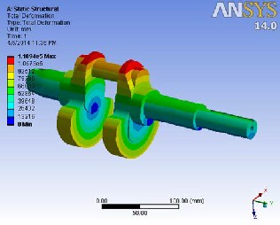
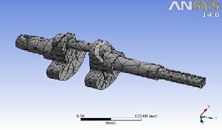
Fig. No. 1: Mess of the crank shaft.
IJSER © 2014 http://www.ijser.org
Fig.no.2: Nickle Chrome steel
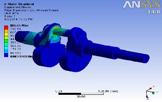
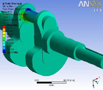
Fig. No. 3: Shear stresses.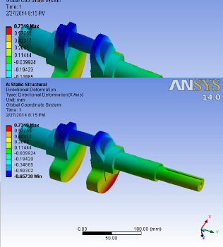
Int ssue 4, April-2014 1251
ISS
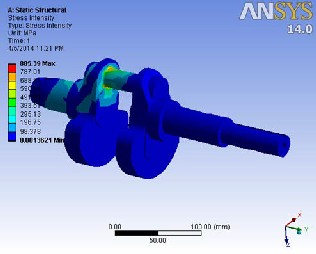
Fig. No. 5: Directional deformation of the crankshaft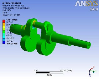
Fig. no. 6: Middle principal stress of the crankshaft.
Fig. No.8: Middle principal stress of the crankshaft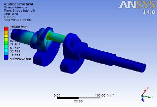

Fig. No. 9: Stress intensity of the crankshaft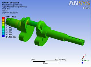
Fig. No.7: Middle principal stress of the crankshaft
IJSER © 2014 http://www.ijser.org
Fig. No.10: Middle principal stress of the crankshaft
International Journal of Scientific & Engineering Research, Volume 5, Issue 4, April-2014 1252
ISS
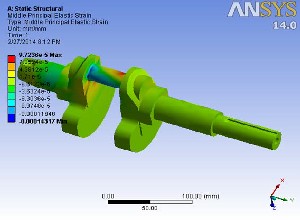
Fig. no.11: Middle principal elastic strain of the crankshaft
Table 1: Type stress and FEA analysis
Type of stress | FEA analysis |
Shear stresses | 59.89 (reference paper) |
Shear stresses | 59.964 (our calculation) |
Directional deformation | 0.7319 (mm) |
Middle principal stress | 68.914 (MPa) |
Stress intensity | 160.86 (MPa) |
Middle principal elastic strain | 9.7236 × |
Table 2: Compression between nickel chrome and structural steel
In this paper, the crankshaft model was created by pro/E 5 soft- ware. After that the model was created by pro/E is imported to Ansys workbench.
Above Result shows that FEA results conformal matches with the software calculation so we can say that FEA is a good tool to re- duce time consuming Ansys workbench. The maximum defor- mation appears at the center of crankpin neck surface. The maxi- mum stress appears at the fillets between the crankshaft journal and crank cheeks and near the central point journal. The edge of main journal is high stresses area.
The value of the von-Misses stresses that comes outs from the analysis is for less than material yield stress so our design is safe and we should go for optimization to reduce the material and cost.
After performing static analysis we performed dynamic analysis of the
crankshaft which result shows more realistic whereas static analysis provides an overestimate results. Accurate stresses and deformation are critical input to fatigue analysis and optimization of the crankshaft.
Analysis results, so we can say that Dynamic FEA is a good tool reduce costly experimental work. By observing the static analysis results shows that stress assesses using nickel chrome steel and structural steel crank shafts from a single cylinder four stroke engine are within the permissible stress value. So using nickel chrome steel and structural steel is good for crank shafts but as compared between nickel chrome and structural steel, nickel chrome is best suited material over the structural steel.
We are gratitude and valuable suggestion from director Dr.Amar singh and highly obeliesed and kindness of HOD ME (Mr. Satish kumar Diwedi) & Mr. Mahesh Kumar Singh Asst.Prof. EC De- partment of BIT, GIDA Gorakhpur for his kind supports and courage to write a paper.
[1] Yu Ding and Xiaobo Li.,2011, “ Crankshaft Strength Analysis of a Diesel Engine Using Finite Element Method,” Asia-Pacific Power and Energy Engineering Conference
[2] Yu Gongzh.i, Yu Hongliang., Duan Shulin., 2011, “Crankshaft
Dynamic Strength Analysis for Marine Diesel Engine,” Third Inter- national Conference on Measuring Technology and Mechatronics Automation.
[3] Prakash, V., Aprameyan, K., and Shrinivasa, U.,1998, “An FEM Based Approach to Crankshaft Dynamics and Life Estimation,” SAE Technical Paper No. 980565, Society of Automotive Engi- neers
[4] Stephens, R. I., Fatemi, A., Stephens, R. R., and Fuchs, H. O., 2001, “Metal Fatigue in Engineering,”2nd edition, John Wiley and Sons, New York, NY,USA co
[5] MENG Jian., LIU Yong-qi., LIU Rui-xiang., and ZHENG Bin.,2011,“Intension Analysis of 3-D Finite Element Analysis on
380 diesel crankshaft,” International Conference on Computational and Information Sciences
[6] Jian Meng., Yongqi Liu., Ruixiang Liu.,2011,“Finite Element Analysis of 4-Cylinder Diesel Crankshaft, ” I.J. Image, Graphics and Signal Processing, 5, 22-29
[7] Prakash, V., Aprameyan, K., and Shrinivasa, U.,1998, “An FEM Based Approach to Crankshaft Dynamics and Life Estimation,”
IJSER © 2014 http://www.ijser.org
International Journal of Scientific & Engineering Research, Volume 5, Issue 4, April-2014
ISSN 2229-5518
SAE Technical Paper No. 980565, Society of Automotive Engi
neers
1253
IJSER lb)2014