International Journal of Scientific & Engineering Research, Volume 2, Issue 12, December-2011 1
ISSN 2229-5518
Extraction of Characteristics Quantities and Electro-Technical Modeling of Electrodynamic Direct Radiator Loudspeaker
Shaiyek Md. Buland Taslim, Shaikh Md. Rubayiat Tousif, Md. Asiqur Rahman, Shauk Muntaha Murshid
Khan, Noor Ehteshamul Azad, Md. Shahnewaz Bhuiyan
Abstract— This paper documents a comprehensive study of loudspeaker modeling to propose such a model that could be used for dimensioning the driver element of an electrodynamic direct radiator loudspeaker system. A lumped-parameter model for such a driver element mounted in an infinite baffle is presented after being derived from careful consideration of the physical principles related to the electro-mechano-acoustic transduction mechanism of the driver element under inspection. Different characteristics quantities such as resonance frequency, Q-number, acoustic efficiency at maximum radiated sound power, frequency response and electrical impedance were extracted from the models representing the loudspeaker driver elements of diameter 8”, 16” and 32”. Subsequently the outcomes were compared and their behaviors verified with the help of extensive simulation results.
Index Terms— Characteristics quantities, Comparison, Electro-technical modeling, Electrodynamic Loudspeaker, Lumped parameter model, SPICE, Simulation, 8” and 16” and 32” loudspeaker driver.
—————————— ——————————
o perform mechanical work is amongst one of the very important field of application of electrical energy. The phenomena regarding the force that originates related to electrical and magnetic field are the ones that are usually get exploited for such application of electrical energy. But amongst these two, the forces originating from magnetic fields are technically are of more importance. The distinction that one usually makes here are the one between current forces that originate from the interaction between different current paths, e.g. forces between two current carrying conductors and forces that act between different magnetic conductors that carry magnetic flux. These lead one to talk about current forces and reluctance forces. In certain cases the combination of these types of forces is used. The modeling of loudspeaker is deemed to be important for its ability to dimension an appa- ratus that utilizes such forces and the access to such a model that describes the actual magneto-mechanical transduction proves to be a valuable resource where an electric model de- fines the behavior of an electro-mechanical device in a circuit. Loudspeaker is a type of transducer which incorporates three level of transduction termed as electro-mechano-acoustic transduction, i.e. they convert electrical energy into mechani-
cal energy, which in turn is converted into acoustic energy.
————————————————
Shaiyek Md. Buland Taslim is graduate student.
Shaikh Md. Rubayiat Tousif is currently a lecturer.
Md. Asiqur Rahman is a graduate in EEE from AIUB, Bangladesh,
PH-8801753720968. E-mail: md.asiqur.rahman@gmail.com
Shauk Muntaha Murshid Khan is a graduate in EEE from AIUB,
Bangladesh, PH-8801675578254. E-mail: khanshauk@gmail.com
Noor Ehteshamul Azad is a graduate in EEE from AIUB, Bangladesh
Md. Shahnewaz Bhuiyan is a graduate in EEE from AIUB, Bangladesh
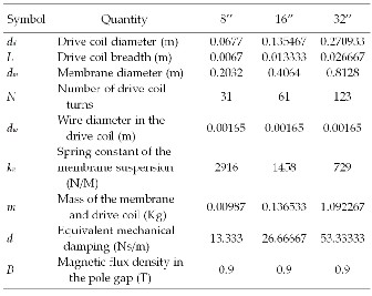
Drive coil diameter: It is the diameter of the speaker coil wound around a paper or aluminum which is set on a permanent magnet.
Drive coil breadth: It is the thickness of the coil.
Membrane diameter: It is the diameter of the membrane
of the speaker which is attached to the coil and pivoted
to the suspension of the speakers.
Number of drive coil turns: It is the number of coil turns
is the voice coil of the speaker.
Wire diameter in the drive coil: One of the factors that indicate the power of the speaker is the wire diameter.
Thicker wire can carry heavy current, increasing the power output of the speaker.
Spring constant of the membrane suspension: It defines
the range of the speaker membrane displacement with-
out rupturing the speaker membrane.
Mass of the membrane and the drive coil: Mass of the
membrane and the drive coil affects the Cmass in the equivalent circuit of loud speaker and can also increase
the gain at low frequencies.
Equivalent mechanical damping of the membrane,
Magnetic Flux density in the pole gap: The permanent magnetic flux density also defines the power of the loud speaker output. As strong as the magnet flux density it will increase the power output.
IJSER © 2011
International Journal of Scientific & Engineering Research, Volume 2, Issue 12, December-2011 2
ISSN 2229-5518
re: The electrical resistance of the drive coil.
Le: The electrical inductance of the drive coil.
L’e: Leakage inductance of drive coil, taken as 1μH.
Lcomp: The electrical equivalent model of suspension of the membrane of the loudspeaker taken as b2l2cm.
Rdamp: The electrical equivalent model for the effect of damping of membrane and drive coil is a resistive phe-
nomenon which can be calculated as (b2l2) cm.
Cmass: The electrical equivalent model for the mass of the loudspeaker membrane and coil taken as m / (b l ) .
Rdamp: The electrical equivalent of the power radiated from the loudspeaker and is modeled as a resistance that can be calculated as (b l ) / (cA) .
Cdamp: It is the electrical equivalent of the damping oc- curs because of air pressure on the face of load speaker
this can be calculated as (8a A) / (3 b2l 2 ) .
Modeling means the process of organizing information about a given system which is in our case an electrodynamic louds- peaker and the said information obtained by analysis of the physical system at a fundamental level, yet involving approx- imation sufficient to simplify the model into an approachable form. To start analyzing system the key physical quantities needs to be measured beforehand. For the cases presented here which comprises of three samples of loudspeaker drivers which were designed to deliver output of frequency ranging from base to mid-range, those key physical statistics were measured and presented in the Table 1.
TABLE 1
PHYSICAL QUANTITIES MEASURED FOR LOUDSPEAKER DRIVERS
WITH DIAMETER OF 8”, 16” AND 32”
Analogies can be very convenient for conducting analysis in unexplored fields. By dint of analogies an unfamiliar system may be compared with one that is better known. In this case the known being the realm of electrical circuits governed by Kirchhoff’s and Ohm’s law which can help to sidestep the analysis of motion of mechanical systems like loudspeaker. By careful use of analogies, from the parameters measured direct- ly from the loudspeaker driver elements under inspection, the values of the lumped parameter components that comprise the electrical equivalent model of the transducer were calculated by equating them into the basic formulae regarding the elec- trical resistance and inductance while incorporating the physi- cal elements from the electrical domain of the electro- mechano-acoustic transducer. While producing the analogical models for the mechanical and acoustic components in the transducer the concept of mobility analogy was employed, which can be found gracefully explained in the early texts like Beranek [1]. While developing the model of the transducer advanced modeling approximations suggested by Watkinson [2] was also taken into account. Finally for calculating the rad- iation impedance presented by the air medium to the diaph- ragm of the electrodynamic loudspeaker driver, the approxi- mations presented by Engdahl and Edin [3] were accepted.
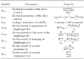
Table 2 documents a detailed list of the mathematical mod- els of the electrical, mechanical and acoustic components play- ing key roles in the electro-mechanic transduction process of loudspeaker system.
TABLE 2
MATHEMATICAL MODELS FOR THE LUMPED COMPONENTS USED
IN THE ELECTRICAL EQUIVALENT CIRCUIT MODEL
ρ = resistivity of the material of the coil = 1.72 × 10⁻⁸(For Annealed Copper),
Ω = ohm, H = henry, F = farad.
m = meter, N = newton, Kg = kilogram, s = second, T = tesla.
Now equating the sets of equation given in the Table 2 with the values of the measured quantities from the Table 1 it is very easy to find the magnitudes of the lumped parameter components which will form the final electrical equivalent model of the transducer, which is in the case presented is an electrodynamic direct radiator loudspeaker.
IJSER © 2011
International Journal of Scientific & Engineering Research, Volume 2, Issue 12, December-2011 3
ISSN 2229-5518
TABLE 3
LUMPED PARAMETERS CALCULATED FOR LOUDSPEAKER
DRIVERS WITH DIAMETER OF 8”, 16” AND 32”
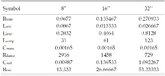
As the magnitudes of all required lumped parameters are cal- culated, they can be used to form the electrical equivalent model for the transduction process of an electrodynamic loudspeaker. Formation of the equivalent circuit was done by the rules dictated by the admittance analogy. So it can be seen in the circuits that the lumped components representing the mechanical and acoustic components of the loudspeaker are connected in parallel with the source while the components derived from the electrical domain remains in series.
Fig. 1 shows the implementation of the equivalent circuits in popular SPICE software, PSpice where it can be seen that the modeled equivalent software is being feed with an AC source of magnitude 12V and output at the acoustic imped- ance element is being traced by voltage and current probe.
Following characteristics quantities were extracted by simulat- ing the derived model of the electrodynamic loudspeaker with the help of simulation software PSpice.
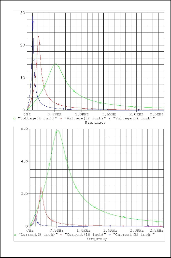
It is the frequency fres for which the power radiated by a sys- tem which is in this case a loudspeaker, is maximum. To ob- tain the output power characteristics of a loudspeaker using the equivalent model, the power across the radiating compo- nent in the model needed to be determined. The radiating components of the derived model happens to be Rrad which is modeled as a resistance and to get the power across this com- ponent the voltage and current across Rrad needs to be deter- mined first. Fig. 2 shows the voltage and current characteris- tics of loudspeaker of different river diameter at frequency ranging from 1μ Hz to 2.5k Hz.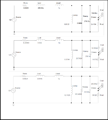
(a)
(a)
(b)
(b)
(c)
Fig. 1. Equivalent circuit of electrodynamic loudspeaker drivers of diameter (a) 8”, (b) 16” and (c) 32” modeled in PSpice.
Fig. 2. Plot of (a) output voltages and (b) output currents in PSpice.
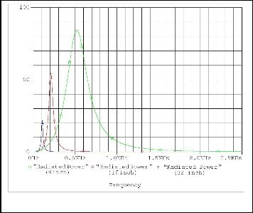
The output power characteristic of the loudspeaker was found by multiplying the voltage and current. Fig. 3 shows the output power characteristic obtained by aforesaid process. The peak values for the curves were found which gave the fre- quency at the maximum radiated power which is indeed the resonant frequency, fres and was documented in the Table 4.
IJSER © 2011
International Journal of Scientific & Engineering Research, Volume 2, Issue 12, December-2011 4
ISSN 2229-5518
After getting waveform of both input and output power, the efficiency can be calculated easily by dividing the output power by the input. Fig. 5 shows the graph obtained by the aforementioned process for the acoustic efficiency.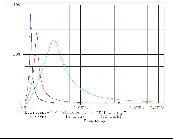
Fig. 3. Plot of output acoustic power for loudspeaker drivers with different diameters in PSpice.
Q factor is the degree of selectivity or narrowness of the fre- quency response as is defined as follows -
Fig. 5. Plot of acoustic efficiency for loudspeaker drivers with different diameters in PSpice.
![]()
Q Fres
f1 f2
where
f1 fres and
f2 fres
The frequency response can be represented in a form of sound intensity level which as per specification of ANSI S1.8-1969[4]
Here f1 and f2 are the frequencies at which the radiated
power is half of the power radiated at resonant frequency, fres
that is 0.5Pmax. Using the aforementioned equation Q factor for all three cases of loudspeakers were calculated and subse-
quently documented in the Table 4.
Efficiency is the ratio of output power to the input power. So to determine the efficiency the input needs to be calculated first. The input power drawn by the electrodynamic louds- peaker was found by multiplying the input voltage and cur- rent to the loudspeaker driver. Fig. 4 shows the plot of output power characteristics over the frequency range of 70 - 2.5k Hz.
is given by the expression, Lw = 10Log10(P/Po) where P is the radiated sound power and Po is the reference power equal to
10-12 W. Fig. 6 shows the graph obtained by the means of the
aforementioned equation of intensity in the frequency range of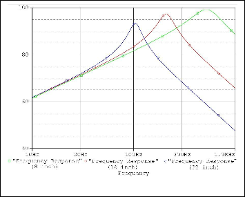
10 - 1k Hz in semi-log scale.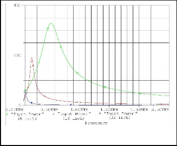
Fig. 6. Frequency response for loudspeaker drivers with different diameters in PSpice.
Fig. 4. Plot of input electric power for loudspeaker drivers with different diameters in PSpice.
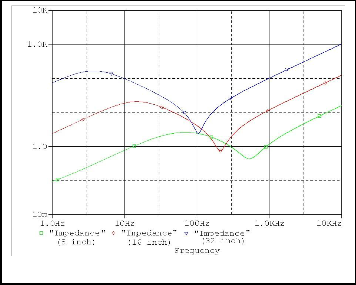
The electrical impedance can be found by the application of
Ohm’s law i.e. by dividing input voltage by input current. Fig.
7 shows the graph obtained for electrical impedance by afore- said process at frequency range of 1 - 10k Hz in full logarith-
mic scale. From the graph electrical impedance at the frequen- cy of 1k Hz was measured and documented in the Table 4.
IJSER © 2011
International Journal of Scientific & Engineering Research, Volume 2, Issue 12, December-2011 5
ISSN 2229-5518
From the quantitative comparison shown in Table 4, it can be seen that the Q-number, maximum efficiency and electrical impedance were increasing with the increase in diameter of loudspeaker driver element. However, the maximum power radiated and resonant frequency and electrical impedance were found decreasing with the increase in diameter of louds- peaker driver element. This work also proves that the maxi- mum efficiency does not coincide with the resonant frequency which can be clearly seen in the quantitative comparison in Table 4.
Fig. 7. Plot of electrical impedance for loudspeaker drivers with differ- ent diameters in PSpice.
TABLE 4
COMPARISON BETWEEN RESULTS FROM LOUDSPEAKER DRIVERS WITH DIAMETER OF 8”, 16” AND 32”
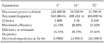
W = watt, Hz = hertz, Ω = ohm.
[1] Leo L. Beranek, Acoustics. Woodbury, New York.: American Institute of
Physics, Inc., pp. 47-55, 1996.
[2] John Watkinson, “Transducer Drive Mechanisms,” Loudspeaker and Headphone Handbook, John Borwick, ed., Oxford, U.K: Focal Press, pp. 89-95, 2001.
[3] G. Engdahl, H. Edin, R. Eriksson, S. Hörnfeldt and N. Schönborg, Electro-technical Modeling and Design. Stockholm, Sweden.: Kun- gliga Tekniska Högskolan (KTH), pp. 121-130, 2010.
[4] Leo L. Beranek, “Basic Acoustical Quantities: Levels and Decibels,” Noise and Vibration Control Engineering: Principles and Applications, István L. Vér, ed., New York.: John Wiley & Sons, Inc., pp. 19-20,
2005.
Table 4 documents a quantitative comparison of the characte- ristics quantities extracted from the simulation of the derived electrical equivalent circuit of the loudspeaker.
Apart from these quantitative relations some qualitative re- lation can also be observed from plots of the characteristics quantities shown in the last section. Notable amongst such qualitative relations is the trend in change in magnitude of the characteristics quantities with the change of the drive diame- ter. In all the cases the trend is found to be exponential in na- ture.
By observing the trend in the comparative plotting of effi-
ciency for loudspeaker drivers of different diameters, it can be
predicted that perfectly efficient transduction can only be
achieved if the drive is infinitely wide.
Also by noticing the trend in the relative plotting of fre-
quency responses of loudspeaker drivers of different diame- ters it can be seen that at low frequency region loudspeaker of
all size produces sound of similar intensity.
IJSER © 2011