International Journal of Scientific & Engineering Research, Volume 4, Issue 11, November-2013 275
ISSN 2229-5518
N.SAMBASIVARAO
Associate Professor and Head NRI institute of Technology,agiripalli nsraohodeee@gm ail.com
Dr.J.Amarnath Professor,Department of EEE, JNTU,Hyderabad amarnathjinka@Yahoo.com
Dr.V.Purnachandrarao
Professor,Department of EEE,
DVR & Dr.HS MIC college of Technology
Abstract— In a power systems,power flows from generating center’s to the load centers.In this process many things require investigation,such as flow of Active power(MW ) and Reactive power(MVAR) in transmission lines for different loading conditions. This paper presents a new method to Enhance Active,Reactive Power in a deregulated Powersystem.In deregulated electricity market transmission overloading occurs when there is insufficient transmission capcity to simultaneously accommodate all constraints for a transmission line.The Increased power demand has forced the power system to operate very closer to its stability limits.So Transmission Overloading,Voltage instability and power loss problems are arise in the power system. These are very serious problems which cause damage to the power system.The above mentioned problems are mitigated by incorporating Series Facts device in optimal location by Sensitivity analysis.The Simulation results were successfully tested on modified IEEE 14 bus system using MATLAB-SIMULINK .
Index Terms— Deregulated powersystem, Thyristor Controlled Series Capacitor (TCSC), Enhancement , Overloading, Total VAR Powerloss, Active ,Reactive power flow.
—————————— ——————————
In the recent year with the deregulation of the electricity market the traditional concepts and practice of the power sys- tem are changed.As power systems are becoming more com- plex it requires careful design of the new devices for the oper- ation of controlling the power flow in transmission sys- tem,which should be flexible enough to adapt to any momen- tary system conditions.The operation of an ac power transmis- sion line,is generally constrained by limitations of one or more network parameters and operating variables by using FACTS technology such as Thyristor Controlled Series Capacitor (TCSC) Active, Reactive power flow in the power system can be regulated.
Because of the Economic considerations, Instalation of facts Controllers in all the buses or lines is impossible and Unnecessary.There are Several methods for finding the opti- mal location of FACTS devices in a power system.In [1],sencitivity approach is used to find the optimal location for placement of TCSC[6].The reduction of total system reactive Power loss method is one used to find optimal loation for placement of series FACTS device. Power flow index is used to find optimal location of FACTS device mitigation of over- loading.The method firstly put all the busses in the orderby voltage reactive power sensitivity then choose the optimal location and appropriate capability of Thyristor controlled
series capacitor (TCSC).
The issue of transmission overloading is more pronounced in
deregulated and competitive markets and needs a special treatment.In this environment, independent system opera- tor(ISO) has to relieve the overloading,so that the system is maintained in secure state. To Enhance power flow ISO can
use mainly two types of techniques which are as follows: A. Cost free means : using sreies FACTS devices
B. Re-dispatching the generation amounts
Among the above two methods cost free means do have
advantage such as not touching economical matters, So
GENCO and DISCO will not involved. FACTS devic-
es,especially series FACTS devices like TCSC are considered
one such technology that reduced the transmission overload-
ing,powerloss (active,reactive) and allows better utilization of existing grid infrastructure,along with many benfits.
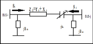
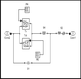
The basic Thyristor –Controlled Series Capacitor scheme, proposed in 1986 by Vithayathil is shown in figure 1. It con- sists of the series compensating capacitor shunted by a Thy- ristor-controlled Reactor. In a practical TCSC implementation, Several such basic compensators may be connected in series to obtain the desired voltage rating and operating characteristics.
————————————————
N.Sambasiva Rao received M. Tech in Electrical Power Engineering and
B.Tech degree in Electrical & Electronics Engineering from JNTU Hydera- bad, India.. He is perusing his Ph.D from JNTU, Hyderabad, India.
IJSER © 2013 http://www.ijser.org
International Journal of Scientific & Engineering Research, Volume 4, Issue 11, November-2013 276
ISSN 2229-5518
index is method based on the sensitivity of total system active and reactive power loss with respect to control variable of the FACT device.
The power loss sensitivity index with respect to this control variable can be formulated as
aij
![]()
= ∂QL
∂X
Loss sensitivity with respect to TCSC
ij
∂Q R 2 − X 2
![]()
L = [v2
+ v 2
− 2v v
cos(δ − δ
ij
![]()
( 2
ij
2 )2
∂X ij
i j i j
n n
i j
Rij + X ij
Q = ∑
∑
P P
+ Q Q
+ ∈
Q P
− P Q
L i = 1 j = 1
ij i j
i j
ij j i
j i
The series impedance of a high voltage transmission line is usually inductive,with only 5 to 10 percentage of resitance
Where a , β , γ and ∈ are loss coefficients computed from the elements of the bus impedance matrix and the bus voltage defined as :
γ
This provides convenient condtion to control the steady state impedance of transmission line by adding both a Thyrister Controlled Series Capacitor(TCSC) and a Thyristor Controlled
a ij
ij
![]()
= ViV j
cos(δ i −δ j )
c c c c
Series Reactor
βij
γ ij
![]()
=
sin (δ i −δ j )
Pij Q P ji Q Pic Q P jc Q
Determined from [7] Method.
A General equivalent circuit of TCSC injected in transmis- sion line is shown in fig2.
γ ij =
ViV j
![]()
X ij
ViV j
cos(δ i −δ j )
∈ij =
X ij
![]()
ViV j
cos(δ i −δ j )
The objective of the device placement may be reduction in the real power loss of a particular line,reduction in the total sys- tem real power loss,reduction in the total reactive power loss and reduction in the overloading of the system.Loss sensitivity
4. Criteria for Optimal placement for TCSC
The FACTS device should be placed on the most sensitivity bus or line. For the TCSC the location is the line with most positive sesetivity index. The TCSC should be placed on the line having most positive loss sensitivity index.
5.1 Simulation results for modified IEEE 14-bus system. Test results are optained by considering practical IEEE 14 – bus system.OPF soluction is obtained on the system to deter- mine the optimum genatation schedule than satisfied the ob- jective of minimizing the losses from the desire transations and controling of voltage magnitude. Here the sensitive index for TCSC has been calculated for the placement of FACTS de- vice. The FACTS device placement method known as sensi- tivity index has been tested on IEEE 14- bus system.
IJSER © 2013 http://www.ijser.org
International Journal of Scientific & Engineering Research, Volume 4, Issue 11, November-2013 277
ISSN 2229-5518
14-bus system has 5 generators and eleven load buses.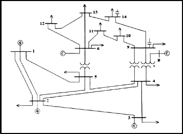
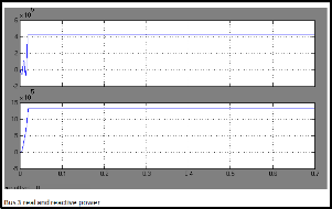
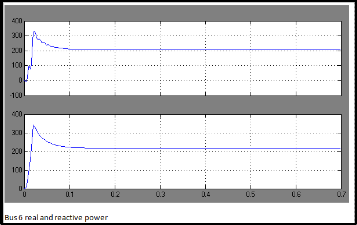
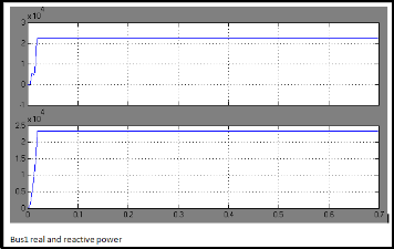
5.1 Simulation results on IEEE 14-bus system without
TCSC
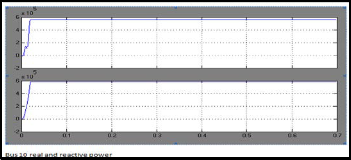
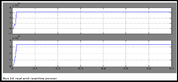
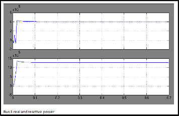
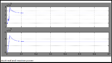
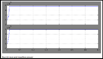
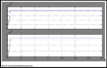
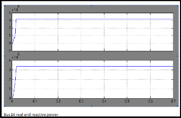
Test results are obtained by considering practical IEEE 14-bus system.Real and Reactive Power at each bus shown following graphs for without TCSC.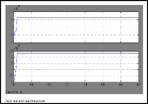
IJSER © 2013 http://www.ijser.org
International Journal of Scientific & Engineering Research, Volume 4, Issue 11, November-2013 278
ISSN 2229-5518
Above results repragents Real and Reactive power at various
Buses.

Power flow profile of the system for each each bus is present- 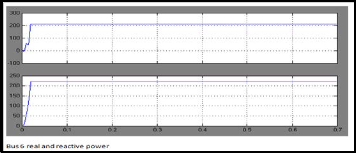 ed below.
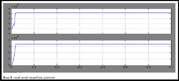
IJSER © 2013 http://www.ijser.org
International Journal of Scientific & Engineering Research, Volume 4, Issue 11, November-2013 279
ISSN 2229-5518
From table:2, the line 1-5 has the most positive sensitivity fact or. So this is the best location for placement of Thyristor Con- trolled Switched Capacitor [TCSC] to relieve congestion in the network.By placing the TCSC in the line 1-5, the congestion in the network is relieved.
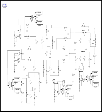
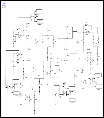
5.2 TCSC modeling Using Simulink
The complte system has been repragented in terms of Sim- ulink blocks in a single integral model.
5.2 Simulation results on IEEE 14-bus system with TCSC
In this section IEEE 14 –buspractcal system has been presented to numerically demonstrate its performance.It has been used
to show quantitatively, how the TSCS performs.The original network is modified to include the TCSC.This compensates
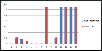
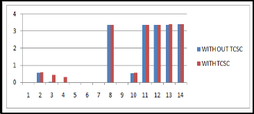
the line between any of the buses.The TCSC is used to regulate the Active and Reactive power flowing in the line at a prespec- ified value.The MATLAB-SIMULINK model is used to find control settings of TCSC for the prespecified Real and Reactive power flow between any buses and the power flow between the lines are observed the effects of TCSC. The FACTS device placement method known as sensitivity index has been tested on IEEE 14- bus system. After incorparating TCSC the Active and Reactive Power flow can be improved which is shown in Table:3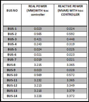
IJSER © 2013 http://www.ijser.org
International Journal of Scientific & Engineering Research, Volume 4, Issue 11, November-2013 280
ISSN 2229-5518
JSER ©
International Journal of Scientific & Engineering Research, Volume 4, Issue 11, November-2013 281
ISSN 2229-5518
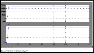
Above results repragents Real and Reactive power at various
Buses.
6 Conclusions:
The contribution of TCSC towards the improvement of Power flow(Active and Reactive) been tested on IEEE 14 bus sys- tem.The FACTS device (TCSC) located at optimal locations is observed to have a better voltage profile and power loss. FACTS devices such as TCSC by controlling the power flow in the network can help to reduce flows in overloaded lines. Be- cause of the considerable costs of FACTS devices, It is im- portant to obtain optimal location for placement of these de- vices. The results presented in this paper show that sensitivity index along with TCSC. So, it can cocluded that after the in- corparation of TCSC the power flow between the lines can be improved.
ACKNOWLEDGEMENTS
We, the authors are very grateful to the Chairman of NRI group of InstitutionsDr. R. Venkat Rao and Principal of NRI Institute of Technology Dr. C. Naga Bhaskar. Without their assistantship the work could not be completed.
REFERENCES:
[1]L.Rajalakshmi,M.V.Suganyadevi,S.Parameswari, “Congestion Management in Deregulated Power System by Locating Series FACTS Devices,” Interna-tional journal of Computer applica- tions,Vol.13,pp 0975-8887,Jan2011.
[2] B.Likitha, J.Srinivasa Rao, J.Amarnath “Sensitivity Approach for Efficient Location of TCSC in a Deregulated Electricity Mar- ket,” IOSR Journal of Engi-neering, ISSN:2250-3021,Vol.2, pp 09-
15,June 2012.
[3] A.R Abhyankar,Prof.S.A.Khaparde “Introduction to Deregula- tion in Power Industry,” IIT Bombay.
[4] K.Vijayakumar, “Optimal location of FACTS Devices for Con- gestion Man-agement in Deregulated Power System,” Interna- tional Journal of Computer Applications,Vol.16, pp.0975-
8887,feb2011.
[5]J.Namaratha Manohar,Amarnath Jinka, V.Poornachandra Rao, “Optimization of Loss Minimization Using FACTS in Deregulated Power System,” Innovative System Design and Engineer- ing,Vol.3,ISSN 2222-1727,2012.
[6] Mrinal Ranjan,B.Vedik, “Optimal Location of FACTS Devices in a Power System by Means of Sensitivity Analysis” Science Road Publishing Corpora-tion- Trends in Electrical and Computer Engineering TECE 1(1) 1-9,2011.
IJSER © 2013 http://www.ijser.org
International Journal of Scientific & Engineering Research, Volume 4, Issue 11, November-2013 282
ISSN 2229-5518
[7] J.Srinvasarao, Dr.Amarnath “Transmission Congestion Man- agement comparitve studies in Rsrtructured Power System,” International Journal of scientific & Engineering Re- arch,Volume4,Issue8,August-2013.
[8] Harry Singh, Shangyou Hao, Alex Papalexopoulos, “Trans- mission Con-gestion Management in Competitive Electricity mar- kets” IEEE Transactions on power systems,Vol.13,No.2,May 1998.
[9] Naresh Acharya, N.Mithulananthan, “Locating series FACTS devices for congestion management in deregulated markets” Elec- tric Power systems re-search 77(2007) 352-360.
[10] Srinivasa Rao Pudi, S.C.Srivastava, “Optimal Placement of TCSC Based on A Sensitivity Approach for Congestion Manage- ment,” Fifteenth National Power System Conference, IIT Bombay, Dec2008
[11] D.J. Gotham and G.T. Heydt, 1998, Power flow control and power flow studies for system with FACTS devices IEEE Trans, power system, and Vol. 13 no.1.
[12] G.H. Hingorani, 1993 Flexible AC transmission system IEEE
spectrum Apr 1993.
[13] H.Ambriz.Perez et. al.,2000 and C.Fuerte-Esquivel Advanced SVC models for Newton-Raphson load flow and Newton optimal power flow studies IEEE Power Transactions on Power Systems vol. 15 pp. 129-136.
[14] H.C. Leung and T.S. Chung,2000 Optimal power flow with a versatile FACTS controller by Genetic Algorithm approach Pro- ceeding of the 5th international conference on Advances in power system control, operation and management APSCOM pp. 178-
183.
[15] W.O. Stadlin and D.L. Fletcher, 1982 voltage versus Reactive current model for Dispatch and control IEEE Transactions on Power Apparatus and Systems vol.PAS-101 no. 10 pp. 3751-3758
Oct 1982.
[16] Preecha Preedavichit and S.C.Srivastava, 1995 Optimal reac- tive power dispatch considering FACTS devices Electrical power research, vol. 48, pp. 251-257 .
[17] N.G. Hingorani and L. Gyugyi, 2000 Understanding FACTS: Concepts and technology of Flexible AC Transmission Systems, IEEE Press, ISBN 0-7803-3455-8.
[18] M.Nomizain and G.Andersson,1993 Power flow control by
use of controllable series components IEEE Transactions on Power
Delivery vol. 8 no. 3 pp. 1420-1429.
Author Biography

N.Sambasiva Rao received the B.Tech degree in Electrical & Electronics Engi- neering and M. Tech in Electrical Power Engineer- ing from JNTU Hyderabad, India. He has 12 years experience in teaching. He is perusing his Ph.D from JNTU, Hyderabad, India. He published a 8 research papers in various International Journals and
2 research papers in National Conferences. He is the Member of International Association of Engineers (IAENG) and Life member of ISTE.
He is currently working as Associate Professor and Head of the department in Electrical & Electronics Engineering at NRI Institute of Technology, Agiripalli, India. He got “Best Achiever award of Andhra Pradesh “By NCERT, New Del- hi, India. His Areas of interest include Electrical Machines, control Systems and power System Protection
IJSER © 2013 http://www.ijser.org