International Journal of Scientific & Engineering Research, Volume 5, Issue 9, September-2014 1230
ISSN 2229-5518
Employing a Suppression Filter for MC-CDMA Overlay
Ahmed E. EL-Mahdy
Professor in Information Engineering
& Technology, German University in Cairo, Egypt ahmed.elmahdy@guc.edu.eg
Ashraf Samy, Ph.D MTC, Kobry El-Koba Cairo, Egypt ashraf16628@yahoo.com
Ahmed Mostafa Elbakly
Arab Academy for Science, Technology &
Maritime transport in Cairo, EGYPT
aelbakly1964@yahoo.com
In this paper, the performance of multicarrier direct sequence code division multiple access (MC-DS-CDMA) system equipped
with a suppression filter is analyzed. A suppression filter is used in the MC-DS-CDMA receiver for suppressing narrowband interference (NBI) over a Rayleigh fading channel. The NBI is assumed to be multi binary phase shift keying narrow band (BPSK NB) signals which exist in all subcarriers of the MC-CDMA system. The effect of suppression filter coefficients, MC- DS-CDMA system parameters, and the NBI parameters on the performance of the system is studied. The analysis shows that, the suppression filter can improve the MC-CDMA system performance significantly, and then increases the MC-CDMA system capacity. It is shown that, increasing the number of taps to be more than nine taps increases the complexity of the filter and does not add any performance gain to the system. The system with a suppression filter has better performance than the system without a suppression filter at a range of values of the ratio of the offset of the interference carrier frequency existing in
a subband to the half spread spectrum bandwidth of this subband, (q), which varies from zero up to a greater value of ( q ) at
which using the suppression filter is useless. This value of q at which the system with and without a suppression filter have the same performance depends on the level of the signal to interference power ratio.
In recent years, code division multiple access (CDMA) has become a technology of choice for wireless communication networks due to high security, high spectral efficiency and greater capacity. This multiple access method offers distinct advantages in suppressing interference and intentional jammers [1]. It is well known that the DSSS systems have inherent interference suppression capabilities. However, when the spreading gain is restricted and the interfering signal is very strong, the spreading gain cannot provide sufficient degree of interference suppression capability. To solve this problem, some signal processing techniques must be employed to further improve the system performance [2]. Under such circumstances, an effective NBI suppression scheme is required. NBI suppression before despreading in the receiver can improve the performance significantly. Many NBI suppression techniques in DSSS systems have been proposed in the previous research and are generally classified into three categories, which are time-domain methods, transform domain methods and multiuser detection (MUD) methods [3]. In [4] a linear suppression filter at a receiver of the single carrier DS-CDMA system is employed to reduce the NBI. In [5], an adaptive linear prediction version of least mean square (LMS) filter is applied to reject NBI. In [6], a non linear prediction technique is introduced and the dynamic convergence behavior of the adaptive nonlinear prediction filters is analyzed. In [7] a new kind of nonlinear filter called nonlinear Lattice and Transversal Joint ( LTJ ) filter is proposed. A discussion was introduced of their SNR improvement and convergence speed in NBI suppression in DS-SS communications and their complexity. For the transform-domain NBI suppression schemes the commonly used transforming schemes are Fourier transform, discrete cosine transform and Karhaunen-Loeve Transform (KLT) [8–10]. In [11] a new and powerful method for suppressing narrowband interference (NBI) in direct sequence spread spectrum (DS/CDMA) communication system is developed. This technique is based on the linear minimum mean square error (MMSE) algorithm for multiuser detection. The performance of the proposed method against NBI is compared with the performance of some previous linear and nonlinear NBI suppression methods. It is seen that this method outperforms all these previous techniques of NBI suppression. In [12] it is shown that the non-linear predictor have not proven as successful in CDMA systems as in single-user SS communication systems because the effectiveness decreases for the increasing number of users. Also, the NBI rejection in synchronous DS-CDMA systems based on zero-forcing (ZF) code-aided techniques is analyzed. In [13] linear predictor and adaptive NBI Re-estimation algorithms are combined with code-aided method. This proposed approach shows that a much
IJSER © 2014 http://www.ijser.org
International Journal of Scientific & Engineering Research, Volume 5, Issue 9, September-2014 1231
ISSN 2229-5518
better performance can be achieved than the pure code aided approach. Compared with the transform-domain methods, the
time domain filtering can eliminate the interference thoroughly with less impairment to useful signals. On the other side, time- domain filtering is of less complexity than the MUD scheme with some penalty of performance [3].
MC-CDMA has recently been proposed as an efficient multicarrier transmission scheme for supporting multiple access communications, which combines CDMA and orthogonal frequency division multiplexing (OFDM) techniques. It receives considerable attention because of its advantages in frequency diversity and multipath fading resilience [14]. The parallel transmission of data over multiple simultaneous carriers makes the OFDM system to be more robust against frequency selective fading or narrowband interference, some subcarriers may be degraded, others will be unaffected [15]. In [16] the performance of a MC-DS-CDMA system is investigated under the effect of multipath fading and narrowband interference. It is shown that this approach exhibits a NBI suppression effect, along with robustness to fading, without requiring the use of either an explicit RAKE structure or an interference suppression filter. But this reference assumes that the NBI does not exist in all subbands of the MC proposed system. In [17] closed form expressions of the average bit error probability of the MC-DS- CDMA system with channel estimation errors in the presence of partial band, broadband and multitone jamming are derived in Rayleigh fading channel. It is concluded that the MC-DS-CDMA system under jamming has a superior performance than the single carrier DS-CDMA system. It is also deduced that in partial band jamming the smart jammer should be present in all subbands of the system in order to be effective. So in [17] the performance of the MC-DS-CDMA system with channel estimation errors is studied in presence of different types of interference. But this reference does not investigate any suppression techniques to these interferences. In [18], the performance of MC-CDMA ultra-wideband (UWB) communication system is studied in the presence of NBI and with the employing of a suppression notch filter in each subband. It is shown that when the number of subcarriers jammed by NBI is small, the MC receiver without notch filters can work well, on the other hand for large number of subcarriers jammed by NBI, using notch filters can improve the MC system performance. But this reference assumes the existence of the suppression filter in each subband and does not study the effect of the number of tapes of the notch filter on the performance of the MC system. However, this reference considered the NBI as a Gaussian random process with a flat spectrum. In [19], the performance of MC-CDMA overlay in UWB application is studied. It is shown that, the NBI reduction can be done by using notch filters at the transmitter. At the receiver, the NBI suppression is fulfilled by minimum mean square error detection technique. Also this reference considers the NBI as a Gaussian random process with a flat spectrum.
In this paper we consider the NBI as multi BPSK NBI. Moreover, the average bit error probability of the MC-DS-CDMA system subjected to multi BPSK NBI and equipped with a suppression filter is derived. The effect of suppression filter coefficients, MC-DS-CDMA system parameters, and the NBI parameters on the performance of the system is studied. The paper is organized as follows. In Section 2, the system model is presented. In Section 3, the performance of the MC-DS- CDMA system with the use of a suppression filter in presence of multi BPSK NBI is derived. In Section 4 the determination of the suppression filter coefficients is deduced. Section 5 provides the numerical results and the conclusions are given in Section
6.
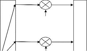
The transmitter block diagram of the MC-DS-CDMA system of user k is shown in Fig. 1 [20, 547]. The binary source data
sequence
bk (t )
of the kth
user is first spread by random binary sequence
ck (t )
![]()
with processing gain N = Tb Tc , where
1![]() Tb and 1
Tb and 1![]() Tc stands for the bit and chip rates, respectively. After that, the spread signal modulates U different subcarriers. Finally, the U binary phase shift keying (BPSK) carrier-modulated signals are added together to form the transmitted signal. The transmitted signal of user k in the MC-DS-CDMA system can be expressed as [20]:
Tc stands for the bit and chip rates, respectively. After that, the spread signal modulates U different subcarriers. Finally, the U binary phase shift keying (BPSK) carrier-modulated signals are added together to form the transmitted signal. The transmitted signal of user k in the MC-DS-CDMA system can be expressed as [20]:
U
![]()
sk (t ) = ∑
u =1
2P bk (t )ck (t )cos(2πfu t + φku )]
(1)
where P is the transmitted power of the MC-DS-CDMA signal, U is the number of subcarriers,
bk (t )
is the baseband data
sequence of user k, and ck (t ) is the spreading waveforms of user k. The autocorrelation function
ρTc
(τ ) of ck
(t ) is given by![]()
![]()
![]()
τ
ρ (τ ) = 1 − T ,
τ ≤ Tc
Tc c
0
![]()
τ ![]() ≥ Tc
≥ Tc
(2)
Finally,
f u ; u = 1, 2, …, U, are the subcarrier frequencies and φku ; u = 1, 2, …, U are the initial phases of subcarriers. In the![]()
MC-DS-CDMA system the subcarrier spacing between two adjacent subcarriers is 1 Tc where Tc
is the chip duration. When
the spacing frequencies are usually chosen to be orthogonal to each other after spreading. Therefore, the minimum between
two adjacent subcarriers is assumed to be
2![]() Tc , there exists no spectral overlap between the spectral main-lobes of two
Tc , there exists no spectral overlap between the spectral main-lobes of two
IJSER © 2014 http://www.ijser.org
International Journal of Scientific & Engineering Research, Volume 5, Issue 9, September-2014 1232
ISSN 2229-5518
adjacent subcarriers [16]. In this case, the total spreading bandwidth of the MC-DS-CDMA system Wss
disjoint subbands, each subband has bandwidth ( Bs ) equals to 2![]() Tc .
Tc .
is divided into U
The communication channel is considered as frequency selective Rayleigh fading channel with additive white Gaussian noise (
AWGN ). We assume that![]()
2 Tc ≤ (∆B)c , where (∆B)c
is the coherence bandwidth of the channel. This assumption implies
that all subcarriers are subject to independent fading. Furthermore, it is assumed that![]()
Tm ≤ 1 , where T is the multipath delay
Tc
spread of the channel. This assumption implies that the subcarrier signals experience no frequency selectivity or no significant dispersion. Moreover, the channel is assumed to be slowly fading i.e. the complex channel gain corresponding to each
subcarrier does not change significantly during one bit interval. Let
g k ,u be the channel complex gain observed by the u-th
carrier of the k-th user. The real and imaginary parts of
g k ,u
are assumed to be uncorrelated Gaussian distributed random
variables, each with zero mean and variance σ 2 , and is represented by
g k ,u
= d k ,u
exp ( jψ
k ,u
(3)
The amplitude d k ,u has a Rayleigh distribution and the phase ψ k ,u
has a uniformly distribution.
The receiver block diagram of the MC-DS-CDMA system is shown in Fig. 2. In the MC-DS-CDMA system, frequency diversity is achieved by combining the outputs of U branches. The received signal enters the suppression filter, which is shown
in Fig. 3, whose impulse response is
M 2
∑α mδ (t − mTc ). Where α − M1 ....α 0 .....α M
} are the optimum tap weights with central
2
m=− M 1
tap α 0 = 1, M 1 ≥ 0 and M 2 ≥ 0 . It is noted that M 1 and M 2 stand for the numbers of taps on the left and right sides of the
center tap, respectively. For
M 1 ≠ 0
and
M 2 ≠ 0 , the filter is double sided suppression filter, whereas for
M 1 = 0
and
M 2 ≠ 0 or
M 1 ≠ 0 and
M 2 = 0 , the filter is a single-sided suppression filter. The suppression filter uses the past and / or
future values of the received signal to predict NBI current value, and then subtracts the predicted value from the received signal current (actual) value. The suppression filter will be discussed in details in section 4. Assuming perfect channel
r
f
estimation, the output of the transversal filter
, is multiplied in each branch by the conjugate of the fading channel gain
g ∗ then passing through a DS despreader, and a PSK demodulator. Then, the outputs of all branches are combined and the
real part of the combined output
X k is compared to a zero threshold to make a decision about the data bit of user k.
In this section, the theoretical performance of the MC-DS-CDMA system with a suppression filter in presence of multi
BPSK NBI is derived. The multi BPSK NBI is assumed to have a total power J W
Hence, the power of each BPSK NBI is given by
distributed over U equal power BPSK NBI.![]()
J w = W
U
(4)
Furthermore, it is assumed that, the number of carriers in the total spreading bandwidth Wss is known. The multi BPSK NBI is
equal to
U
J (t ) = ∑ J u (t ) , where
J u (t ) is the BPSK NBI corresponding to the subcarrier u and it can be represented as
u =1
J u (t ) =
![]()
2 J w j(t )cos(2π ( f u + ∆ )t + β u )
(5)
Where ∆ stands for the offset of each interference carrier frequency in any branch from the subcarrier frequency of the MC-
CDMA signal in that branch, and
β u denote the interference phase. The information sequence
j (t )
![]()
has a bit rate 1 T j ,
where T j
denotes the duration of one bit. The autocorrelation function
ρT j
(τ ) of
j(t )
is given by (2) with Tc replaced by
T j . Therefore, the interference bandwidth in each subband is B
= 2T −1 ( it is assumed that B < B
). An important quantity
j j j s
is the ratio of the interference bandwidth in each subband to the spread spectrum system bandwidth in that subband![]()
![]()
p = B j = Tc
Bs T j
. Assuming perfect power control, the received signal associated with K asynchronous users in a Rayleigh
fading channel can be expressed as
K U
![]()
r(t) = ∑∑
k =1 u =1
2Pbk (t − τ k )g k ,u ck (t − τ k )cos(2πfu t + ϕ k ,u )+ n(t) + J (t)
(6)
IJSER © 2014 http://www.ijser.org
International Journal of Scientific & Engineering Research, Volume 5, Issue 9, September-2014 1233
ISSN 2229-5518
where ϕk ,u = φk ,u − 2πfuτ k
is a random variable uniformly distributed in [0, 2 π ),
J (t )
is a multi BPSK NBI, n(t ) is a
sample function of a stationary zero mean complex Gaussian process, independent of signal and with power spectral density
(psd)
N 0 / 2 . Assume the reference user is the k-th user and also assume that τ k = 0 for notational convenience.
The output of the suppression filter of the k-th user, r
f
(t ) , can be expressed as
rk (t) =
M 2 U
αm
![]()
2Pbk (t − τ k − mTc )gk ,u ck (t − τ k − mTc )cos(2πfu (t − mTc ) + ϕk ,u ) + n(t − mTC ) + J (t − mTC )}}
(7)
f ∑ ∑
m = − M1
u =1
The output of the correlator of branch i of the k-th user corresponding to the 0th data bit can be expressed as
Tb
xk ,i =
∫ rk f
0
(t ) g k ,i ck (t )2 cos(2πf i t + φk ,i )dt
(8)
By substituting ( 7 ) into ( 8 ),
xk ,i can be written as
xk .i
M 2
= ∑
m = −M1
Tb U
α m ∫ ∑
0 u =1
![]()
2Pbk
(t − mTc )g
k ,u
∗
k ,i k
(t − mTc )cos(2πf u
(t − mTc ) + ϕ
k ,u
)ck
(t )2 cos(2πf i t + φ
k ,i
)dt
Tb K U
![]()
+ ∫ ∑ ∑
2P g
j ,u
b j (t − τ j
− mTc ) c j
(t − τ j
− mTc ) cos(2πf u
(t − mTc ) + ϕ
j ,u
∗
k ,i
ck (t)
0 j =1
u =1
j ≠k
× 2 cos(2πf t + φ
Tb
)dt + ∫ n(t − mT )g ∗ c
(t )2 cos(2πf t + φ
)dt
(9)
i k ,i
0
Tb
c k ,i k
i k ,i
![]()
+ ∫ 2J w
0
j(t − mTc )cos(2π ( f u
+ ∆)(t − mTc ) + λu
∗
k ,i k
(t )2 cos(2πf i t + φ
k ,i
)dt
The internal interference term, due to the reference user, which is caused by the taps of the suppression filter excluding the zero tap can be safely ignored [5], and since different carriers are orthogonal, the integral in the first and second term of (9) is
nonzero only for u = i
![]()
Tb
and otherwise equals to zero then
xk , i
can be written as
xk .i
= ∫ 2Pbk
0
M 2
+ α
(t )g
K
k ,i
k ,i dt
![]()
2P g
g ∗ cos(θ
Tb
)∫ b
(t − τ
− mT
) c (t − τ
− mT
) c (t ) dt
∑
m=− M1
m ∑
j =1
Tb
j ,i
k ,i
j ,i j
o
j C j
j C k
(10)
+ ∫ n(t − mT )g ∗ c
(t )2 cos(2πf t + φ
)dt
c k ,i k
0
Tb
i k ,i
![]()
+ ∫ 2 J
g ∗ c
(t )cos(2π∆(t − mT ) + η )dt
w k ,i k
0
c i
where
θ j ,i = ϕ j ,i − ϕ k ,i , and ηi = φk ,i − β i
The above expression can be reduced to
K
xk .i
= Dk , i + ∑ I k , j + nk , i + J k , i
j =1
k ≠ j
(11)
where the terms on the right hand side of (11) are described below.
The first term, Dk ,i , represents the desired signal of the reference user at the zeroth tap of the suppression filter and is given by
IJSER © 2014 http://www.ijser.org
International Journal of Scientific & Engineering Research, Volume 5, Issue 9, September-2014 1234
ISSN 2229-5518
Tb
D = ∫
![]()
2Pb
(t )g
g ∗ dt =
![]()
2PT b [0] g
g ∗ =
![]()
2PT b [0] d 2
k ,i
0
k k ,i
k ,i
b k k ,i
k ,i
b k k ,i
(12)
where bk [0] is the transmitted zeroth data bit. The useful signal power given d k ,i is equal to![]()
2 ( 2 )2
S d k ,i
= 2PTb
d k ,i
(13)
The second term
I k , j is the multiple access interference ( MAI ) term due to the j
user (k ≠
j ) and it is given by
I k , j
M 2
= ∑ α
m=− M1
M 2
![]()
2P g
j ,i
∗
k ,i
cos(θ
j ,i
Tb
)∫ b j
o
(t − τ j
− mTc ) c j
(t − τ j
− mTc ) ck
(t ) dt
(14)![]()
= ∑α m {
2P g
j ,i
∗
k ,i
cos(θ
j ,i
) (b j [−1] R
k , j
(τ (m)) + b j [0]Rˆ
k , j
(τ (m)))}
m=− M1
where τ (m) = τ j + mTc is uniformly distributed in [0,2π ].
In this term of (14) the variables
τ
Rk , j (τ )
Tb
and
Rˆ k , j (τ )
are the partial cross-correlation functions defined by
Rk , j (τ ) = ∫ c j (t − τ ) ck (t) dt and
0
Rˆ k , j (τ ) = ∫ c j (t − τ ) ck (t) dt
τ
respectively. The variance of
I k , j
corresponding to the ith
subcarrier is identical to that one deduced in [5], which was for single carrier, and it is given by
P T 2 (K − 1)d 2 M 2
M 2
σ MAI
= ∑
α m +
∑α mα m+1
(15)
2 b
3N
k ,i
2
m=− M1
m=− M1
The third term, nk ,i , is the noise component at the i
correlator output of the kth
user and it is given by
nk ,i
M 2
= ∑α m
m = − 1
Tb
∫ n(t − mTc
0
k ,i ck
(t )2 cos(2πf i t + φ
k ,i
)dt
(16)
M
and it is shown in the appendix that, the variance of the noise component, nk ,i , is given by
M 2
2 = (
2 ) ∑ 2
(17)
σ n,i
N 0Tb d k ,i
α m
m =− M1
The fourth term,
J k ,i , is the NBI component at the ith correlator output of the kth user and it is given by
M 2
J = α
![]()
Tb
∫ 2 J
j(t − mT )g ∗ c
(t )cos(2π∆(t − mT ) + η )dt
k ,i
∑ m w
m = −M1 0
c k ,i k
c i
(18)
The variance of J k ,i is given by
σ 2 = E[J 2 ]
J k ,i
M 2 M 2
Tb Tb
![]()
![]()
∗
= α m α m 2 J w g k ,i
E[ j(t1 − m1Tc ) j(t 2 − m2Tc )ck (t1 )ck (t 2 )cos(2π∆((t1 − m1Tc ) + η i )
(19)
∑ ∑ 1
m1 =− M1 m2 =− M1
2 ∫ ∫
0 0
× cos(2π∆((t 2 − m2Tc ) + η i )]dt1dt 2 }
M 2
σ 2 =
M 2
α α J
Tb Tb
d 2 ∫ ∫ ρ
(t − t
− m T
+ m T )ρ
(t − t
)cos(2π∆(t − t
− m T
+ m T ))dt dt
(20)
J ∑ ∑ m1
m1 =− M1 m2 =− M1
m2 w
k ,i
0 0
T j 1 2 1 c
2 c Tc 1 2
1 2 1 c
2 c 1 2
IJSER © 2014 http://www.ijser.org
International Journal of Scientific & Engineering Research, Volume 5, Issue 9, September-2014 1235
ISSN 2229-5518
For variable transformation, let t1 − t2 = τ
and t1 +![]()
∂t1
t2 = θ , and this implies that τ + θ = 2t1 and τ − θ = 2t2
![]()
∂t2
the Jacobian of
the transformation can be calculated as Jac=
∂τ
∂t1
∂θ
![]()
∂τ = 1
∂t2 2
∂θ
![]()
![]()
and since dt1dt 2 = Jac dθdτ
so (20) becomes
M 2
σ 2 =
M 2
α α J w d 2
Tb 2Tb −![]() τ
τ ![]()
![]()
![]()
∫ ∫ ρ
(τ − m T
+ m T )ρ
(τ )cos(2π∆(τ − m T
+ m T ))dθdτ
![]()
J ∑ ∑ m1
m =− M m =− M
m2
2
k ,i T j
1 c 2 c Tc
1 c 2 c
1 1 2 1
M 2 M 2
−Tb τ
Tb
= α α
J w d 2 ∫ ρ
(τ − m T
+ m T )ρ
(τ )(2T
![]()
![]()
− 2τ )cos(2π∆(τ − m T
+ m T ))dτ
(21)
∑ ∑ m1
![]()
m2 2
k ,i T j
1 c 2 c Tc b
1 c 2 c
1 1 2 1 Tb
m =− M m =− M −
M 2 M 2
Tb ![]()
τ − m T
![]()
+ m T ![]()
![]()
τ τ
= α α
J d 2
1 − 1 c
2 c 1 −
T 1 −
cos(2π∆(τ − m T
+ m T ))dτ
∑ ∑ m1
m2 w
k ,i ∫
T
T b T
1 c 2 c
m1 =− M1 m2 =− M1
−Tb
j
c b
![]()
![]()
Since τ
≤ Tc , (21) equals
M 2 M 2
![]()
Tc τ
![]()
![]()
τ ![]()
τ
σ 2 =
α α J
T d 2
1 − p
− m + m
1 −
1 −![]()
cos 2π q τ − m + m
dτ
(22)
J ∑ ∑
m1 m2 w b
k ,i ∫
T 1 2
T T
T 1
2
m1 =− M1 m2 =− M1
−Tc
c
c
b c
Let![]()
x = τ
Tc
![]()
so dx = dτ and
Tc
dτ = Tc dx , and at
τ = Tc
this implies that
x = 1and at
τ = −Tc
this implies that
x = −1.
Therefore, the variance of the narrowband interference is given by
J
M 2 M 2 1
![]()
x
σ 2 =T 2 w d 2
![]()
α α
(1 − p x − m + m
)(1 − x )1 −
cos(2π q (x − m + m ))dx
![]()
![]()
![]()
(23)
J b N
k ,i
∑ ∑ m1
m1 =− M1 m2 =− M1
m2 ∫
−1
1 2
1 2
The above expression can be reduced to
M 2 M 2
2 T 2 J w 2 2
![]()
σ J =
b d
k ,i
∑ ∑α m α m σ
(m1 , m2 )
(24)
Where σ
(m1, m2 ) is given by
1
N
1 2
m1 =− M1 m2 =− M1
![]()
x
σ (m1 , m2 ) = ∫ sign [(1 − p x − m1 + m2 )](1 − x )1 − N cos(2π q (x − m1 + m2 ))dx
(25)
2 ![]()
![]()
![]()
![]()
−1
Where sign [x] = x or
zero for
x ≥ 0 or x 0 , respectively, and q = ∆Tc
denotes the ratio of the offset of the interference
carrier frequency in the ith subband to the half spread spectrum bandwidth of this subband.
Collecting the above results, the decision variable
xk ,i
given by (11), consists of a useful term
Dk ,i
and a total interference
K
term [ MAI ∑ I k , j
j =1
j ≠ k
+ Gaussian noise
nk ,i + narrowband interference
J k ,i ]. The total interference has the conditional
variance given, d k ,i , of
PT
2 (K − 1)d 2 M 2
M 2
2 J
M 2 M 2
σ 2 =
b
k ,i
2α 2 +
α α + (N T d 2 )
α 2 +T 2 w d 2
α α σ 2 (m , m )
(26)
xk , i 3N
∑ m
m = − M
∑ m
m = − M
m+1
0 b k ,i
∑ m
m= − M
b N
k ,i
∑ ∑ m1 m2
m = − M m = − M
1 2
1 1 1
1 1 2 1
When the number ( K ) of active users is large and according to the central limit theorem given, d k ,i , the sum of the MAI term
K
∑ I k , j , and the narrowband interference term J k ,i can be approximated by a conditional Gaussian random variable. Hence
j =1
j ≠ k
given
d k ,i , all interference terms and the noise term can be combined into a single conditional Gaussian random variable.
IJSER © 2014 http://www.ijser.org
International Journal of Scientific & Engineering Research, Volume 5, Issue 9, September-2014 1236
ISSN 2229-5518
Therefore, the conditional signal to noise , MAI interference , and narrowband interference power ratio of the decision variable
xk ,i is given by
![]()
S
![]()
γ = d k , i
k ,i 2σ 2
k , i
2 2
=
P T 2 (K − 1) M 2
M 2
![]()
PTb dk ,i
M 2
J 2 M 2
(27)
b
2α 2 +
α α + (N T )
![]()
α 2 + T 2 w
α α σ 2 (m , m )

∑ m
∑ m m +1
0 b ∑ m
b ∑ ∑
m1 m2
1 2
3N
m = − M
m = − M
m = − M
N m = − M m = − M
1 1 1
1 1 2 1
Combining the outputs of all branches, one obtains the decision variable
U
X k = ∑ xk ,i
i =1
X k which is given by
(28)
Now, combining all signals according to (28), the total SNR
γ t is written as
![]()
E 2 {X
dk ,i } U
γ t =
2Var X k
dk ,i
= ∑γ k ,i
i =1
U
PT 2 ∑ d 2
(29)
b k ,i
= i =1
P T 2 ( K − 1) M 2
M 2
2 J M 2 M 2
b
2α 2 +
α α + (N T )
α 2 + T 2 w
α α σ 2 (m , m )
∑ m
∑ m m +1
0 b ∑ m b
∑ ∑ m1 m2
1 2
3N
m = − M
m = − M
m = − M
N m = − M m = − M
1 1 1
1 1 2 1
Then the conditional error probability,
P(e | {d k ,i }), can be written as
∞ 2
P(e | {d
![]()
}) = Q( 2γ )=
1 exp − z
dz
k ,i
![]()
![]()
t 2 2
(30)
where γ t has a chi-square distribution given by [23]
1
π
2γ t
![]()
L −1
P (γ
t
![]()
) = (L − 1)! Γ L γ t
exp(− γ t Γ )
(31)![]()
Where Γ is the average signal to noise ratio and it can be written as![]()
PT 2
Γ = b
P T (K − 1) M 2
M 2
2 J M 2 M 2
b ∑2α 2 +
∑α α
+1 + (N0T ) ∑α 2 + T 2 w
∑ ∑αm αm σ 2 (m1, m2 )
3N
m
m = −M 1
m m
m = −M1
b m
m = −M1
N
1 2
m1 = − M1 m2 = −M1
M 2
(K − 1)
M 2
−1
E 2
−1
J 2 M 2
=
∑2α 2 +
∑α α
+1 + b
∑α 2 + w
∑ ∑αm αm σ 2 (m1, m2 )
(32)![]()
3N m
m m
N0
m NP 1 2
m
= − M1
m = − M1
m = − M1
m1 = − M1 m2 = − M1
where Eb
is the energy per bit for the MC-DS/CDMA system ( Eb = PTb ).
Since the separation of adjacent carriers is assumed to be![]()
2 Tc , the total spreading bandwidth
Wss is expressed as
![]()
Wss = (2 Tc ) U . Using this expression and knowing that Tc = Tb
![]()
N , the ratio
![]()
J w P in (32) can be expressed as
![]()
![]()
J w = JW U P P
![]()
= 2 JW N PWss Tb
N j
![]()
= 2 N
Eb
(33)
In (33),
N j = JW
![]()
Wss represents the effective psd of the NB-BPSK interference in the total communication band. Let us
![]()
define the average signal to noise and interference ratio, Γ , as
M 2
(K − 1)
M 2
−1
E 2
E
−1
−1 M 2 M 2
![]()
3N
∑
∑ N0 ∑
![]()
N
∑ ∑ 1 2
Γ =
2α 2 +
α mα
![]()
m +1 + b
α 2 + 2 b
α m α m σ 2 (m1, m2 )
(34)
m = − M 1
m = − M 1
m = − M 1
j
m1 = −
M 1 m2 = − M 1
IJSER © 2014 http://www.ijser.org
International Journal of Scientific & Engineering Research, Volume 5, Issue 9, September-2014 1237
ISSN 2229-5518
Recall that, our goal is to evaluate the performance of the system in terms of average BEP. For this purpose the conditional
BEP in (30) has to be statistically averaged over the random parameter γ t . The average BEP is given by
∞
P av = ∫ P(e | γ t
0
) P
t
(γ t
)dγ t
![]()
= 1
(L − 1)!Γ L
∞
∫γ t
0
![]()
L−1Q(
γ t ) exp(− γ t
![]()
Γj )dγ t
(35)
which, after successive by parts integrations, can be written as [23]:
1 − µ L L−1 L − 1 + l 1 + µ l
where µ is given by [23]:
Pe =
av
![]()
2 l =0 l
![]()
µ = Γ
![]()
2
(36)
(37)
1 + Γ
By substitution of µ from (37) into (36), the average BEP becomes![]()
L
Γ L−1 L −
![]()
l
+ l Γ
P = =1 1 −
av
+ Γ
1 =1
l
+ =1
+ Γ
(38)
2 1
l =0
2 2 1
The employed suppression filter is a two sided transversal filter shown in Fig. 3. This filter attempts to produce an estimate
of the NBI,
J k , and then subtracts this estimate from the received signal,
r (t ) , to cancel the NB interference. This estimate
NBI,
J k , is given by [24]
M 2
J k ∑α m rks −m
m=− M1
m≠0
(39)
Where the sample, rk
, is the input signal of the filter at different taps, and
r ( m = 0), is the central tap input
signal of the filter. Thus the output of the filter,
r , is given by
f
r = r
f s
(40)
The optimum weights of the filter taps, {α
− M 1
....α
.....α
2
}, can be determined by minimizing the mean square error of
the filter output, E[r 2 ]. According to orthogonality principal, in order to minimize mean square error, the error in this case is
r , must be orthogonal to the input signal of the filter,
rk − l . This minimization is given by [24]
M 2
E r −
s
∑α m rk s − m rk s −l = 0
(41)
m = − M 1
m ≠ 0
which yields the following Weiner-Hopf equations [5]
M 2
∑α m R[(l − m)Tc ]+ R(lTc ) = 0
m=− M1
m≠0
(42)
where
l = − M 1 ,.... − 1,1,......, M 2 , l ≠ 0
and
R(lTc ) = E[rk −m rk −l ] is the autocorrelation of the input signal of the
filter and can be expressed as [5]
R(τ ) =
s s
![]()
ρ (τ )cos(2πf iτ )
2
(43)
where
ρ (τ ) is the low pass version of
R(τ ) and it equals
IJSER © 2014 http://www.ijser.org
International Journal of Scientific & Engineering Research, Volume 5, Issue 9, September-2014 1238
ISSN 2229-5518
U
ρ (τ ) = ∑ ρi (τ )
i=1
Where ρi (τ ) is the low pass version corresponding to the subcarrier i . Therefore the Weiner-Hopf equations become
M 2
∑α m ρ [(l − m)Tc ] + ρ (lTc ) = 0
m = − M 1
m ≠ 0
(44)
(45)
The coefficient of the suppression filter can be determined by solving the Weiner-Hopf equations given by ( 45 ). The ith low
pass version,
ρi (lTc ) ,can be written as [5]
ρi (lTc ) = ρ s (lTc ) + ρ n (lTc ) + ρ J (lTc )
(46)
i i i
where ρ s (lTc ) ,
ρ n (lTc ) and ρ J (lTc ) are, respectively, the low pass versions of the desired signal, noise and interference
i i i
functions of the input signal to the suppression filter corresponding to subcarrier i. The desired signal term is given by
1 K
K
ρ s (lTc ) =
E 2P
g k ,i bk (t − τ k )ck (t − τ k ) 2P
g k ,i bk (t + lTc − τ k
)ck (t + lTc − τ k
)
![]()
2
K K
![]()
∑ 1 1
k1 =1
1 1 1
![]()
∑ 2 2
k2 =1
2 2 2
(47)
= P E [g k ,i g k ,i ] E[bk (t − τ k )bk (t + lTc − τ k
)]E [ck (t − τ k )ck (t + lTc − τ k )]
∑ ∑ 1 2
k1 =1 k2 =1
1 1 2
2 1 1 2 2
Since E [ck (t − τ k )ck
(t + lTc − τ k
)]= 0 for k ≠ k
, then (47) can be written as
1 1 2 2 1 2
K 2
ρ (lT ) = P∑ ![]() g ∗
g ∗ ![]()
E[b
(t − τ
)b (t + lT − τ
)]E[c
(t − τ
)c (t + lT − τ )]
si c
k =1
K
k ,i k k k
c k k k k c k
(48)
= P∑ d k ,i E[bk (t − τ k )bk (t + lTc − τ k )]E[ck (t − τ k )ck (t + lTc − τ k )]
k =1
Noting that the autocorrelation function
ρTc
(τ ) of ck
(τ ) is given by
![]()
![]()
![]()
τ
ρ (τ ) = E [c (t )c (t −τ )] = 1 − T ,
τ ≤ Tc
Tc k k
c
0 ![]() τ
τ ![]() ≥ Tc
≥ Tc
(49)
Therefore E[ck (t − τ k )ck (t + lTc − τ k )] is given by
1,
l = 0
E [ck (t − τ k )ck (t + lTc − τ k )] =
0
From (48) and (50), the desired signal term can be written as
2
l ≠ 0
(50)
ρ (lT
i
) = KPd k ,i ,
0 ,
l = 0
l ≠ 0
(51)
The filtered noise term
n(t )
has a flat power spectral density of![]()
N 0 2
with the bandwidth of![]()
2 Tc . Since the
autocorrelation function of a signal is the Fourier transform of its power spectral density function, the low pass version of the autocorrelation of the noise term is given by
Since from ( 52 ) we can deduce that
ρ ni
(lTc
![]()
) = 2 N 0 sinc( l )
Tc
(52)
2 N 0
ρni
![]()
(lTc
) = T ,
l = 0
(53)
0 ,
l ≠ 0
The low pass version of the autocorrelation of the multi NB-BPSK interference is given by
IJSER © 2014 http://www.ijser.org
International Journal of Scientific & Engineering Research, Volume 5, Issue 9, September-2014 1239
ISSN 2229-5518
![]()
ρ J (lTc ) = E [
2 J w j(t )cos (2π∆t + ηi )
1
![]()
2 J w j(t + lTc )cos (2π∆(t + lTc ) + ηi ) ]
![]()
= 2 J w E[ j(t ) j(t + lTc )]
2
[cos (4π∆t + l∆Tc + 2ηi ) + cos (2π l ∆Tc )]
= J w E[ j(t ) j(t + lTc )]cos (2π l ∆Tc )
J w (1 − ![]() l
l ![]() p )cos (2π l q ),
p )cos (2π l q ), ![]() l
l ![]()
=
![]()
≤ int[1 p]
(54)
0 ![]() l
l ![]()
![]()
int[1 p]
Therefore, from (46), (51), (53) and (54) one obtains
2 2 N 0
KPd k ,i +
![]()
+ J w ,
c
l = 0
ρ (lT
) = J
![]()
![]()
(1 − l p)cos(2π lq ),
![]()
![]()
![]()
l ≤ int[1 p]
i c w
(55)
0 ,
Then from ( 44 ) and ( 55 ), the low pass version,
![]() l
l ![]() int[1
int[1![]() p]
p]
ρ (τ ) , is given by
KP +
![]()
2 N 0
Tc
U + J wU ,
l = 0
ρ (lT ) = J
![]()
![]()
U (1 − l p )cos(2π lq ),
![]()
![]()
![]()
l ≤ int[1 p]
(56)
c w
Then from ( 56 ) one obtains where ρ (lT ) is defined as
![]()
0,
![]()
ρ (lTc ) = PUρ (lTc )
![]()
l ≤ int[1 p]
(57)
(K ![]() U ) +
U ) +
![]()
2 NN 0 +
![]()
J w ,
l = 0
PTb P
![]()
![]()
ρ (lT ) = J w (1 − l p )cos(2π lq ),
![]()
![]()
![]()
l ≤ int[1 p]
(58)
Knowing that Eb
= PTb and
![]()
c
P
0,
![]()
![]()
J w = JW
P UP
N j
![]()
= 2 N
Eb
![]() l
l ![]() int[1
int[1![]() p]
p]
, so (58) becomes
E −1
−1
E
![]()
![]() b
b
N
![]()
+ 2N ,
N
l = 0
0
−1
j
![]()
![]()
ρ (lT ) = 2N Eb
![]()
(1 − l p)cos(2π lq ),
![]()
![]()
l ≤ int[1 p]
(59)![]()
c
0,
j
![]()
![]()
![]()
l int[1 p]
By replacing
ρ (lTc ) by
ρ (lTc )
in ( 45 ), we can obtain the coefficients
α m . Table 1 shows the values of the tap
coefficients of the double sided suppression filter for different numbers of taps for each side ( M1 = M 2 = 4, 5, 6, 7 ). Since the values of the coefficients in the two sides are identical, so Table 1 only indicates the values of one side. Then using the deduced values of the coefficients in Table 1, we can obtain the average probability of error and analyze the effect of the values of these coefficients in the performance of the proposed system.
In this section, using the above analytical results, we provide some representative numerical curves illustrating the average
bit error probability of the MC-DS-CDMA system with a suppression filter in the presence of multi BPSK NBI. Unless stated otherwise, it is assumed that the ratio of the offset of the interference carrier frequencies to the half spread spectrum
IJSER © 2014 http://www.ijser.org
International Journal of Scientific & Engineering Research, Volume 5, Issue 9, September-2014 1240
ISSN 2229-5518
bandwidth, q , is equal to zero in each subband, that is, the subcarriers frequencies of the MC-DS-CDMA and multi NB- BPSK interference are identical ( i.e. ∆ = 0 ).
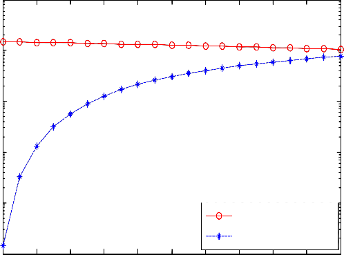
Fig. 4 shows the performance comparison of the system with a double-sided suppression filter and without a suppression filter
as a function of the signal-to noise ratio. Also, the effect of the number of subcarriers U on the system performance with and without a suppression filter is illustrated in the presence of multi NB-BPSK interference. In this figure the results are obtained for 10 active users, 63 chips per bit, the ratio (P) of the interference BW to the spread spectrum BW equals 0.1, and 5 dB signal-to-interference power ratio. It is assumed that the two-sided filter has three taps and is symmetric (i.e., M 1 = M 2 = M = 4 ). The figure shows that, the suppression filter enhances the
system performance greatly. For example, at U = 4 and![]()
Eb N 0 =10 dB, the system without a suppression filter, has
P = 8 ×10 −3 while, the system with a suppression filter has
av
P = 4 ×10 −4 . The figure also shows that the performance
av
of the systems with and without a suppression filter improves by increasing the number of subcarriers U . But, system with suppression filter has significant performance enhancement than system without suppression filter.
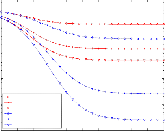
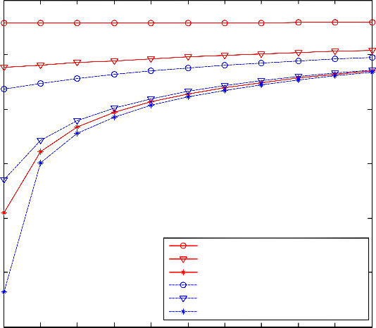
Fig. 5 illustrates average probability of error of the system with a double-sided filter, single sided filter, and without a
suppression filter as a function of![]()
Eb N j . It is shown that the average probability of error of the system without the
suppression filter decreases greatly as![]()
Eb N j
increases, whereas the performance of the system with a double sided or single![]()
![]()
sided suppression filter is improved at small values of Eb N j . It is noted that at large values of Eb N j , for example
at Eb![]()
N j > 20 dB , the system with and without a suppression filter approximately have the same performance. It is also shown
that the double sided filter outperforms the single sided filter at small values of![]()
Eb N j
and at the same number of taps because
the former uses the autocorrelation function of the NB-BPSK interference more efficiently than does the latter.
In Fig. 6 the BER of the system with and without the suppression filter is shown as a function of the ratio (P) of the interference bandwidth to the spread spectrum bandwidth. It is seen from the figure that the system with a double sided filter can suppress the narrowband interference very well when (P) is small, but is ineffective in suppressing the interference when (P) is large. For P = 1, the performance is the same for the system with and without a suppression filter.![]()
In Fig. 7 the BER of the MC-DS-CDMA system with a double-sided suppression filter is plotted as a function of active users ( K ) and for different values of Eb ![]() N j . It is seen that, for a given average BER, the system with a double sided suppression filter can support many more users than can the system without a suppression filter, especially when Eb N j is small. When the
N j . It is seen that, for a given average BER, the system with a double sided suppression filter can support many more users than can the system without a suppression filter, especially when Eb N j is small. When the![]()
interference is not too large (i.e. Eb N j ≥ 20
dB) the system employing a suppression filter can support almost the same
number of users as can the system without a suppression filter.
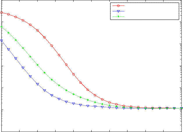
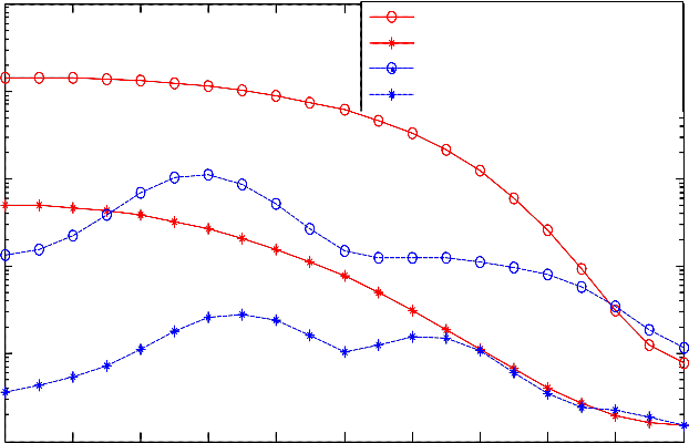
Fig. 8 illustrates the BER performance of the system with a double-sided suppression filter as a function of the ratio ( q ) for
different values of
Eb / N j . It is seen that the performance of the system without a suppression filter ( M = 0) is enhanced
with increasing the ratio ( q ). Furthermore, It is shown that at small values of ( q ) the performance of the system with a
suppression filter outperforms the system without a suppression filter. Whereas at large values of ( q ) the system with and without a suppression filter have the same performance. And this large value of ( q ), at which using a suppression filter is
useless, depends on the value of the signal to interference power ratio. For example, at
Eb / N j
= -5 dB, the system with and
without a suppression filter have the same performance at q > 0.9 whereas at
satisfied at q > 0 .6.
Eb / N j
= 5 dB the same performance is
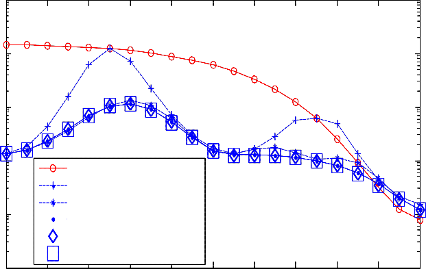
Fig. 9 illustrates the BER performance of the system with a double-sided suppression filter as a function of the ratio ( q ) and
at different values of the number of taps on each side and with
Eb / N j
= -5 dB. It is seen that the performance of the system
without a suppression filter ( M = 0) is enhanced with increasing the ratio ( q ), whereas the performance of the system with a suppression filter depends on the value of ( q ) with different manners. It is seen that when q is very small, the average BER
of the system with a suppression filter for
M ≥ 1 are almost identical. However, the performance improves as M increases, to
more than one and less than four, when q increases. It is also shown that increasing the number of taps to be more than four
taps in each side increases the complexity of the filter and does not add any performance gain to the system either for small or
large values of the ratio ( q ). From another hand when q is very large (i.e., suppression filter have the same performance.
q ≥ 0.85) the system with and without a
In this paper, performance expressions have been obtained for a MC-DS-CDMA system operating over a Rayleigh fading
channel, employing a suppression filter, and under the effect of modulated NB interference. It has been shown that, the MC- DS-CDMA system equipped with a suppression filter has a superior performance than the system without a suppression filter and consequently the system with a suppression filter can support more users. The performance of the MC-DS-CDMA system
IJSER © 2014 http://www.ijser.org
International Journal of Scientific & Engineering Research, Volume 5, Issue 9, September-2014 1241
ISSN 2229-5518
can be improved by increasing the number of subcarriers U, and this improvement is significant when a suppression filter is
employed with the system. In addition, the double sided suppression filter outperforms the single sided suppression filter for the same number of total taps. It has been shown that the double sided suppression filter with nine total taps is sufficient to mitigate the multi BPSK NBI and increasing the number of total taps beyond nine is not necessary. The system with and without a suppression filter have the same performance at certain value of the ratio q, and this value of q varies according to the changes in the level of the signal to interference power ratio.
The third term,
Appendix
Derivative of the variance of the noise component term
nk ,i , is the noise component at the ith correlator output of the kth user and it is given by
M 2
n = ∑α
Tb
∫ n(t − mT
)g ∗ c
(t )2 cos(2πf (t − mT
) + φ
)dt
A.1
k ,i
m=− M1
m
0
c k ,i k
i c k ,i
The variance ( σ n,i ) of
nk ,i
is obtained as follow
2
n,i
= E[n 2 ] =
M 2 M 2
=
α m α m
![]()
∗
k ,i
![]()
2 Tb Tb
E[n(t1 − m1Tc )n(t 2 − m2Tc )]E[ck (t1 )ck (t 2 )]
A.2
∑ ∑ 1
m1 =− M1 m2 =− H1
2 ∫ ∫
0 0
× 4 cos(2πf i (t1 − m1Tc ) + φk ,i )cos(2πf i (t 2 − m2Tc ) + φk ,i )dt1dt 2 }
Since E[n(t )n(t )] = N 0 δ (t − t ) [ 16, 55], consequently we can substitute in the right side of (A.2) to get
1 2 2 1 2
M 2 M 2
Tb Tb
σ 2 =
α α d 2
∫ ∫ 0 δ (t1 − t 2 )E[c
(t1 )c
(t 2 )]2 cos(2πf (t1 − t 2 + m2T
− m1T ))dt1dt 2 }
A.3
n,i
∑ ∑ m1
m1 =− M1 m2 =− H1
m2 k ,i
0 0
k k i c c
where![]()
N 0 is the noise power spectral density (psd) of
2
nk ,i . By
noting that, there is a value only at t1 = t2 and m1 = m2 , then A.3 becomes
2 = 2
M 2 Tb
∑ 2 ∫
2 ( ) =
M 2
2 ∑ 2
σ n,i
d k ,i
α m
N 0 cK
t dt
N 0Tb d k ,i α m
A.4
Which is the proof of (16).
m=− M1
0
m=− M1
[1] Kodithuwakku, J., Letzepis, N. and Grant, A., “Multi-User Decoder Assisted Code-Acquisition in
CDMA Systems,” Communications Theory Workshop (AusCTW), pp. 83 – 88, 1 – 3 Feb. 2011.
[2] Cheng Wang, Maode Ma, Rendong Ying, and Yuhang Yang, “Narrowband Interference Mitigation in
DS-UWB Systems,” IEEE Signal Processing, vol. 17, no. 5, May 2010.
[3] T. Zhao, Z. Yang and Y. Zhao “Partial-code-aided scheme for narrowband interference suppression in direct-sequence spread spectrum systems,” IET Commun., 2010, Vol. 4, Iss. 18, pp. 2240–2251.
IJSER © 2014 http://www.ijser.org
International Journal of Scientific & Engineering Research, Volume 5, Issue 9, September-2014 1242
ISSN 2229-5518
[4] J. Wang, “On the use of a suppression filter for CDMA overlay,” IEEE Trans. Veh. Tech., vol. 48, pp.
405-414, March 1999.
[5] J Wang, and Milstein “Adaptive LMS Filters for Cellular CDMA Overlay Situations,” IEEE Selected Areas in Commun., vol. 14, No. 8, pp. 1548-1559, October 1996.
[6] Fang Liu and Garth, L.M., ‘’Dynamic Convergence Analysis of Adaptive Nonlinear Filters for Narrowband Interference Rejection in Spread Spectrum Systems,’’ International Symposium on Information Theory, pp. 1696 – 1700, 4-9 Sept. 2005.
[7] K. J. Wang and Y. Yao, “The nonlinear adaptive filters for narrow-band interference suppression in DS spread spectrum communications,” Proc. IEEE conference in communication, circuits and systems 2006.
[8] AZMI P., NASIRI-KENARI M.: ‘Generalised Fourier transformdomain technique for narrowband interference suppression in CDMA communication systems’, Electron. Lett., 2001, 37, (10), pp.
652–654
[9] AZMI P., NASIRI-KENARI M.: ‘Narrow-band interference suppression in CDMA spread spectrum communication systems based on sub-optimum unitary transforms’, IEICE Trans. Commun., 2002, E85-B, (1), pp. 239–246.
[10] P. Azmi and N. Tavakkoli: ‘Narrow-Band Interference Suppression in CDMA spread spectrum communication systems using pre-processing based techniques in transform-domain,’, Progress In Electromagnetics Research Letters, Vol. 3, 141–150, 2008.
[11] H. V. Poor, and X. Wang, “Code-Aided Interference Suppression for DS/CDMA Communications-Part I: Interference
Suppression Capability,” Proc. IEEE Trans. Commun., vol.45, no. 9, pp. 1101-1111, Sept. 1997.
[12] Yin Fulian and Guo Lili, “ZF Code-Aided Narrow-Band Interference Suppression for Synchronous DS-CDMA Systems,” Wirless Commun, Networhing and Mobile Computing, International Conference, Oct. 2008.
[13] K. C. Ho, Xiaoning Lu, and Vandana Mehta, “Adaptive blind narrowband interference cancellation for multi-user detection,” Proc. IEEE Trans. Commun., vol.60, no. 3, pp. 1024-1033, March 2007.
[14] T. M. Law, S. C. Chan and Z. G. Zhang “A Turbo receiver for wireless MC-CDMA communications using MAP-EM demodulator with LDPC codes under narrowband interference ,” 12th - Signal Processing Education pp. 94 - 98, 24-27 Sept. 2006.
[15] Haitham J. Taha, M. F .M. Salleh “Multicarrier Transmission Techniques for Wireless communication Systems: A Survey,” Wseas Trans. on Commun. Issue 5, Volume 8, May 2009.
[16] S. Kondo and L. B. Milstein, “Performance of Multicarrier DS CDMA Systems”, IEEE Trans.
Commun., vol.44, no. 2, pp. 238-246, Feb. 1996.
[17] A. E. El-Mahdy, “Error probability analysis of multicarrier direct sequence code division multiple access system under imperfect channel estimation and jamming in a Rayleigh fading channel,” IET Signal/Process., vol. 4, no. 1, pp. 89-101, March 2010.
[18] J. Wang, and L. B. Milstein, “Multicarrier CDMA overlay for ultra-wideband communications,” IEEE Trans Commun., vol. 52, no. 10, pp. 1664-1669, 2004.
[19] W. T. Tung and J. Wang, “MMSE Receiver for Multicarrier CDMA Overlay in Ultra-Wide-Band
Communications,” IEEE Trans. Veh. Tech., vol. 54, no. 2, pp. 603-614, 2005.
[20] H. Lajos, L. Yang, E. Kuan, and K. Yen, Single and Multi-Carrier DS-CDMA: Multi-User Detection, Space-Time
Spreading, Synchronization, Networking and Standards, Wiley-IEEE Press, 2003.
[21] M. K. Simon and M. S. Alouini, “Digital communication over fading channels: A unified approach to performance analysis, New York: Wiley, 2000.
[22] J. G. Proakis, Digital Signal Processing, Principles, Algorithms, and Applications, Person Prentice
Hall, (Fourth Edition) 2007.
IJSER © 2014 http://www.ijser.org
International Journal of Scientific & Engineering Research, Volume 5, Issue 9, September-2014 1243
ISSN 2229-5518
Table 1. Determination of the double sided suppression filter coefficients with K = 10, U=4, N = 63,
(Eb
![]()
N j ) = −5dB
and
(Eb
![]() N0 ) = 20dB, q = 0
N0 ) = 20dB, q = 0
cos(2πf1t + φk1 )
bk (t )
IJSER © 2014 http://www.ijser.org
∑
s (t )
International Journal of Scientific & Engineering Research, Volume 5, Issue 9, September-2014 1244
ISSN 2229-5518
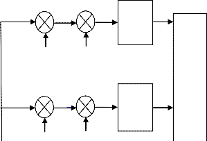
Fig. 1. The transmitter block diagram of the orthogonal MC-DS-CDMA system for the k-th user.
(t )
f
(λ +1)Tb
∫
λTb
xk ,1
g k ,1 ck (t )
2 cos(2πf1t + φk1 )
r (t )
f
IJSER © 2014 http://www.ijser.org
(λ +1)Tb
∫
λTb
xk , 2
∗
International Journal of Scientific & Engineering Research, Volume 5, Issue 9, September-2014 1245
ISSN 2229-5518
Fig. 2. The receiver block diagram of the orthogonal MC-DS-CDMA system with a suppression filter for the k-th user.
rk + M
Tc
rk +1 r
Tc
rk −1 r −
Tc Tc
α −M
α −1
IJSERα© 2014 http://www.0ijser.org 1
α M 2
International Journal of Scientific & Engineering Research, Volume 5, Issue 9, September-2014 1246
ISSN 2229-5518
Fig. 3. The block diagram of the double side suppression filter
IJSER © 2014 http://www.ijser.org
International Journal of Scientific & Engineering Research, Volume 5, Issue 9, September-2014 1247
ISSN 2229-5518
0
10
-1
10
-2
10
-3
10
Without Suppression Filter U = 1
10-4 Without Suppression Filter U = 3
Without Suppression Filter U = 4
With Suppression Filter U = 1
With Suppression Filter U = 3
With Suppression Filter U = 4
-5
10
-10 -5 0 5 10 15 20 25 30 35 40
Eb/N0 [dB]
Fig. 4. BER performance of MC-DS-CDMA system with and without suppression filter with different values of U, number of users K = 10, P = 0.1, N = 63, M = 4 and Eb / N j = 5 dB.
IJSER © 2014 http://www.ijser.org
International Journal of Scientific & Engineering Research, Volume 5, Issue 9, September-2014 1248
ISSN 2229-5518
0
10
Without suppression filter
With double sided filter
With single sided filter
-1
10
-2
10
-3
10
-4
10
-5
10
-6
10
-10 -5 0 5 10 15 20 25 30 35 40
Eb/Nj [dB]
Fig.5. BER performance of MC-DS-CDMA systems with and without suppression filters as a function of Eb / N j , M = 4, K
=10, P = 0.1, N = 63, Eb / N 0 = 20 dB
and U = 4.
IJSER © 2014 http://www.ijser.org
International Journal of Scientific & Engineering Research, Volume 5, Issue 9, September-2014 1249
ISSN 2229-5518
0
10
-1
10
-2
10
-3
10
-4
10
Without Suppression Filter
With DS Suppression Filter
-5
10
0 0.1 0.2 0.3 0.4 0.5 0.6 0.7 0.8 0.9 1
Ratio ( p )
Fig.6. BER performance of MC-DS-CDMA systems with and without suppression filters as a function of the ratio (P) of the
interference BW to the spread spectrum BW, U= 4,
Eb / N j
= -5 dB, N = 63, M = 4, and Eb / N 0 = 20 dB .
IJSER © 2014 http://www.ijser.org
International Journal of Scientific & Engineering Research, Volume 5, Issue 9, September-2014 1250
ISSN 2229-5518
0
10
-2
10
-4
10
-6
10
-8
10
-10
10
-12
10
Without suppression filter Eb/Nj = - 5 dB Without suppression filter Eb/Nj = 5 dB Without suppression filter Eb/Nj = 20 dB With suppression filter Eb/Nj = - 5 dB With suppression filter Eb/Nj = 5 dB
With suppression filter Eb/Nj = 20 dB
0 5 10 15 20 25 30 35 40 45 50
Number of users ( K )
Fig.7. BER performance of MC-DS-CDMA systems with and without suppression filters at different values of
Eb / N j , P =
0.1, N = 63, M = 4,
Eb / N 0 = 20 dB
and U = 4 as a function of the number of active users ( K ).
IJSER © 2014 http://www.ijser.org
International Journal of Scientific & Engineering Research, Volume 5, Issue 9, September-2014 1251
ISSN 2229-5518
0
10
Without Suppression Filter Eb/Nj = -5 dB
Without Suppression Filter Eb/Nj = 5 dB With Suppression Filter Eb/Nj = -5 dB
-1
10 With Suppression Filter Eb/Nj = 5 dB
-2
10
-3
10
-4
10
-5
10
0 0.1 0.2 0.3 0.4 0.5 0.6 0.7 0.8 0.9 1
Fig.8. BER performance of MC-DS-CDMA system with and without a suppression filter as a function of the ratio (q) and at
different values of
Eb / N j , M = 4, p = 0.1, number of users K = 10, N = 63, U = 4 and
Eb / N 0 = 20 dB .
IJSER © 2014 http://www.ijser.org
International Journal of Scientific & Engineering Research, Volume 5, Issue 9, September-2014 1252
ISSN 2229-5518
0
10
-1
10
-2
10
-3
10
Without Suppression Filter M = 0
With Suppression Filter M = 1
-4 With Suppression Filter M = 2
10 With Suppression Filter M = 3
With Suppression Filter M = 4
With Suppression Filter M = 5
-5
10
0 0.1 0.2 0.3 0.4 0.5 0.6 0.7 0.8 0.9 1
Ratio ( q )
Fig.9. BER performance of MC-DS-CDMA system with and without a suppression filter as a function of the ratio (q) and at
different values of M,
Eb / N j = -5, P = 0.1, number of users K = 10, N = 63, U = 4 and
Eb / N 0 = 20 dB .
IJSER © 2014 http://www.ijser.org