International Journal of Scientific & Engineering Research, Volume 3, Issue 1, January-2012 1
ISSN 2229-5518
Eight User, 4Gb/s, Spectral Phase-Encoded OCDMA System in time domain for Metropolitan area Network
Savita R.Bhosale Dr. S. L. Nalbalwar and Dr. S.B.Deosarkar
Dr. Babasaheb Ambdkar Technological University, Lonere, Raigad (MS) India, Pin– 402103
4 Gb/s bit rate for Metropolitan area Network (MAN). Results indicate significant improvement in term Beat Error Rate (BER) and very high quality factor in the form of Quality of Service (QoS). In our analysis, we have used Pseudo Orthogonal (PSO) codes. The simulations are carried out using OptSim (RSOFT).
—————————— ——————————
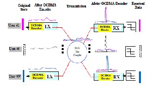
PTICAL code division multiple access (OCDMA), where users share the same transmission medium by assigning unique pseudo-random optical code (OC),
is attractive for next generation broadband access networks due to its features of allowing fully asynchronous transmission with low latency access, soft capacity on demand, protocol transparency, simplified network management as well as increased flexibility of QoS control [1~3]. In addition, since the data are encoded into pseudo- random OCs during transmission, it also has the potential to enhance the confidentiality in the network [4~6]. Figure1. illustrates a basic architecture and working principle of an OCDMA passive optical network (PON) network. In the OCDMA-PON network, the data are encoded into pseudo random OC by the OCDMA encoder at the transmitter and multiple users share the same transmission media by assigning different OCs to different users.
At the receiver, the OCDMA decoder recognizes the OCs by performing matched filtering, where the auto- correlation for target OC produces high level output, while the cross-correlation for undesired OC produces low level output. Finally, the original data can be recovered after electrical thresholding. Recently, coherent OCDMA technique with ultra-short optical pulses is receiving much attention for the overall superior performance over incoherent OCDMA and the development of compact and reliable en/decoders (E/D) [7~12]. In coherent OCDMA, encoding and decoding are performed either in time domain or in spectral domain based on the phase and amplitude of optical field instead of its intensity.
Savita R.Bhosale is currently perusing PhD degree programme in
Electronics and Telecommunication Engineering in Dr. Babasaheb
In coherent time spreading (TS) OCDMA, where the encoding/decoding are performed in time domain. In such a system, the encoding is to spread a short optical pulse in time with a phase shift pattern representing a specific OC. The decoding is to perform the convolution to the incoming OC using a decoder, which has an inverse phase shift pattern as the encoder and generates high level auto- correlation and low level cross-correlations.

The encoders use delay line arrays providing delays in terms of integer multiples of chip times. The placement of delay line arrays and the amount of each delay and phase shifts are dictated by the specific of the signatures. PSO matrix codes are constructed using a spanning ruler or optimum Golomb ruler is a (0,1) pulse sequence where the distances between any of the pulses is a non repeating integer, hence the distances between nearest neighbors,
Ambdkar Technological University, Lonere, Raigad, Pin– 402103
India. Email: sr4bhosale@gmail.com and svtbhosale@yahoo.co.in
Co-Authors Dr. S. L. Nalbalwar and Dr. S.B.Deosarkar are currently working as a professor and Head of the Department at
Dr. Babasaheb Ambdkar Technological University, Lonere, Raigad, Pin– 402103 India. Email: sbdeosarkar@yahoo.com
IJSER © 2012 ttp://www.ijser.org
International Journal of Scientific & Engineering Research, Volume 3, Issue 1, January-2012 2
ISSN 2229-5518
next nearest neighbors, etc., can be depicted as a difference triangle with unique integer entries. The ruler-to-matrix transformation increases the cardinality (code set size) from one (1) to four(4)and the ISD (=Cardinality/CD) from 1/26 to 4/32 = 1/8.The ISD translates to bit/s/Hz when the codes are associated with a data rate and the code dimension is translated into the bandwidth expansion associated with the codes as follows:
t rou put
![]()
I n w t r qu r
r n l ty t r t
![]()
![]()
![]()
1 n w t xp ns on n r
n r
![]()
The enhanced cardinality and ISD, while preserving the OOC property, are general results of the ruler-to-matrix transformation.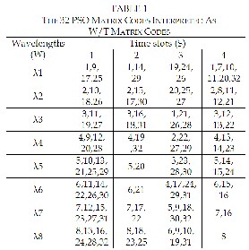
We can convert the PSO matrices to wavelength/time (W/T ) codes by associating the rows of the PSO matrices with wavelength (or frequency) and the columns with time- slots, s s own n l I. m tr sM1….M32 r num r 1…32 n t t l , w t t orr spon n assignment of wavelengths and time-slots. For example, o M1 s (λ1 ; λ1 ; λ3; λ1 ) n M9 s ( λ1,λ4;0;λ7,λ8;0); here the semicolons separate the timeslots in the code. (The codes M1 and M9 are shown in bold numerals.)
We focus on codes like M1 because it shows extensive
wavelength reuse, and on codes likeM9 because it shows extensive time-slot reuse. It is the extensive wavelength and
time-slot reuse that gives these matrix codes their high cardinality and high potential ISD. Four mode-locked lasers are used to create a dense WDM multi-frequency light source. Pseudo-orthogonal (PSO) matrix codes [3] are popular for OCDMA applications primarily because they retain the correlation advantages of PSO linear sequences while reducing the need for bandwidth expansion. PSO matrix codes also generate a larger code set. An interesting variation is described in [1] where some of the wavelength/time (W/T) matrix codes can permit extensive wavelength reuse and some can allow extensive time-slot reuse. In this example, an extensive time-slot reuse s qu n s us for Us r 1 (λ1λ3;0;λ2λ4;0). r r four time slots used without any guard-band giving the chip period of 100 ps. Codeset for time spreading is mapped as
1:{0; λ2;0;λ4}, 2:{λ1;0;λ3;0}…. 8:{λ1; λ2;0;0}. o s t to apply binary phase shift mapped as M1:{ 0;1;0;1;} M2:{1;0;1;0;}….M8:{0;0;1;1;}.(1r pr s nts s π phase shift,0 represents as no phase shift)
SPE O-CDMA system parameters used for simulation
Parameter | Value |
Code weight | 6 |
Channel spacing | 0.4 nm |
Wavelength | 4 at 1550, 1550.4, 1550.8, 1551.2 nm |
Chip time Chip rate | 4 1.25E-10 |
Bit rate Modulation Format | 2.5 Gbs NRZ and RZ |
Fiber length | 60 km to 120 km |
Measurements | Eye diagram, Bit error rate and Quality factor |
1) Lasers (mode locked laser requited to produce 4 wavelength signal)
2) Encoders consisting of required components like fiber delay lines, PRBS, External Modulator, multiplexers
3) Multiplexers
4) Optical fiber of 60 km length
5) De multiplexers
6) Decoders corresponding to each encoder
7) Receiver etc
8) BER analyzer
9) Eye Diagram analyzer
10) Signal analyzer
IJSER © 2012 http://www.ijser.org
International Journal of Scientific & Engineering Research, Volume 3, Issue 1, January-2012 3
ISSN 2229-5518
multiplexed 4 wavelengths according to the NRZ electrical data. For analysis ,Eye Diagram analyzer ,Beat Error tester and Signal analyzer is used.
Encoding Optical CDMA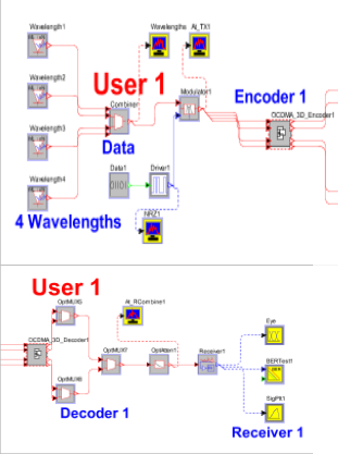
III Simulation of SPE O-CDMA system one user
Optical CDMA system for 1 User
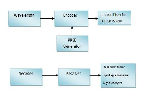
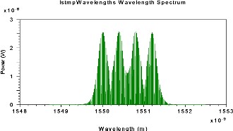
The simulation setup for Spectral Phase Encoding Optical CDMA is shown in figure 3 The MLL is used for generating coherent pulses .The wavelengths range from
1550 nm to 1551.2 nm, with 0.4nm wavelength spacing. Four MLL (wavelengths 1 to4) are used to create a dense WDM multi-frequency light source i.e. carrier signal. This carrier signal is used to modulate the pseudo random bit sequence (PRBS) data of the user. . An intensity modulator which is ExtMod is using on-off keying to modulate the
Optical CDMA for Eight Users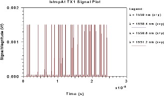
After modulation an encoder is used for encoding the signal. The modulated signals are distributed to the respective encoders, which have been assigned a unique W/T code respective to each encoder. The encoded data from all users are multiplexed by Optical MUX and then passed through a 60 km span of standard single mode optical fiber followed by a loss compensating optical amplifier which is OptAmp.
The output signal from a fiber span is then passed through OptSplit1 to split the signal and routed to the us r’s o r. o r us s opt l f lt rs n nv rs delay line arrays providing delays in terms of integer multiples of chip times and the decoded signal finally arrives at optical receiver (Receiver), BER Test and Eye Diagram. Eye diagram analyzer has been used to take the plot of Eye pattern at the receiver end. Bit error rate values for different number of transmitting users have been taken from BER Tester. The system has been redesigned for different number of users. In spite of the use of orthogonal codes, the main effect limiting the effective signal-to-noise ratio of the overall system is the interference resulting from
IJSER © 2012 http://www.ijser.org
International Journal of Scientific & Engineering Research, Volume 3, Issue 1, January-2012 4
ISSN 2229-5518
the other users transmitting at the same time, which is called Multiple Access Interference (MAI). MAI is the major source of noise in OCDMA systems .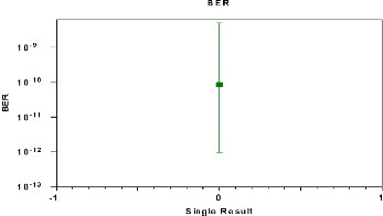
Optical CDMA for Eight active Users
10-4
10-6
10-9
10-13
10-18
10-25
10-35
10-49
10-69
10-98
10-138
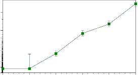
BER
1 2 3 4 5 6 x10⁹
bitrate
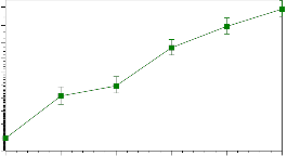
Optical CDMA for Eight active Users
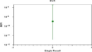
Optical CDMA for Users 1
BER
TABLE 3
10-2
10-4
-6
BER AND Q FACTOR FOR 8 USER SPEO-CDMA
10
10-10
10-16
10-25
10-38
10-58
10-90
10-138
1 2 3 4 5 6 x10⁹
bitrate
Optical CDMA for Users 8
IJSER © 2012 http://www.ijser.org
International Journal of Scientific & Engineering Research, Volume 3, Issue 1, January-2012 5
ISSN 2229-5518
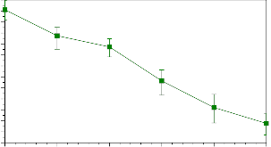
Q2
24
22
20
18
16
14
12
1 2 3 4 5 6 x10⁹
bitrate
.Moreover these results are more realistic as practical impairments have been considered with -15 dB received power and for permissible BER of 10-9.
[1] to k n E. H. r nt, ― rol of opt l MA n ss n tworks‖,
IEEE Communication Magazine 40, 83- 87 (2002).
[2] K. K t y m , X. W n , n H. oto y s , ― t t of t rt n ppl t ons of opt l o v s on mult pl ss (Inv t ),‖ n ECOC’04, (Stockholm, Sweden, 2004), Tu4.6.
[3] X. W n n K. K t y m , ―An lys s of t no s n coherent and
incoherent time-spr n O MA,‖ J. Lightwave Technol 22, 2226-2235, (2004).
[4] . H. k , ― onf nt l ty p rform n of sp tr l-phase-encoded
opt l MA‖, J. Lightwave Technol. 23, 1652–1663, (2005).
Optical CDMA for Users 1
Q2
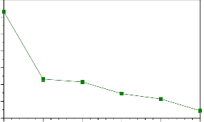
70
60
50
40
30
20
10
0
1 2 3 4 5 6 x10⁹
bitrate
Optical CDMA for Users 8
Figure 8, 9, 10 and 11 shows performance of spectral Phase
Encoding O-CDMA BER and Quality factor.
The multiple access interference effect was also seen at the optical receiver end in optical CDMA which degraded the efficiency of system by increasing bit error rate. Use of spectral phase shift reduced the MAI as seen in the bit error rate performance. The overall MAI is reduced which further enhances the QoS. Which overcomes some of the major demerits of O-CDMA and to makes the SPE O- CDMA system more adaptive and has enhanced the performance of the system in terms of reduction in MAI and improvement in Q Factor.
The spectral phase encoding O-CDMA system designed
for eight users at 4Gb/s .It has been seen that SPE O- CDMA can accommodate up to eight users at 4Gb/s
IJSER © 2012
[5] D. E. Leaird, Z Jiang, and A. M. Wein r, ―Exp r m nt l nv st t on of
security issues in OCDMA: a code-sw t n s m ‖, Electron. Lett. 41,
817-819, (2005).
[6] X. W n , N. W , . M y z k , n K. K t y m , ― o r nt O MA syst m us n P K t form t w t l n t t on‖, IEEE Photonic Technol. Lett. 18, 826-828, (2006).
[7] Z. G o, X W n , N. K t ok n N. W , ― monstr t on of t m -
domain spectral phase encoding/DPSK data modulation using single p s mo ul tor‖, to pr s nt n LEOS Summer Topical 2009, New port, CA, USA, 2009.
[8] Z. Jiang, D. Seo, S. Yang, D. E. Leaird, R. V. Roussev, C. Langrock, M. M.
F j r, n A. M. W n r, ―Four-user 10-Gb/s spectrally phase-coded O-
MA syst m op r t n t 30 fJ/ t‖ IEEE Photonics Technol. Lett., 17,
705-707, (2005).
[9] Xu W n n N oy W ― econfigurable Time Domain Spectral Phase Encoding/Decoding Scheme Using Fibre Bragg Gratings for Two- m ns on l o r nt O MA‖, ECOC’08, P.3.11, September Brussels, Belgium, 2008.
[10] Xu Wang and Naoya Wada.. "Spectral phase encoding of ultra-short optical pulse in time domain for OCDMA application", Optics Express
15(12):7319-7326 (2007).
[11] X. W n , K. M tsus m , A. N s k , N. W , n K. K t y m , ―H
reflectivitysuperstructured FBG for coherent optical code
n r t on n r o n t on‖, Optics Express 12, 5457-5468, (2004).
[12] Al n E W lln r, Poory r , V . Ar , ―A v n techniques to increase the number of users and bit rate in OCDMA n tworks,‖ IEEE Journal of Selected Topics in quantum Electronics , vol.13,2007, pp. 1403-1414
[13] A. J. Mendez, R. M. Gagliardi, V. J. Hernandez, C. V. Bennet and W. J.
L nnon, ―H -performance optical CDMA system based on 2-D optical
ort o on l o s,‖ IEEE Journal of Lightwave Technology, vol. 22, pp. 2409-
2419, Nov. 2004.
[14] Z. Jiang, D. S. Seo, S.-D. Yang, D. E. Leaird, A. M. Weiner, R. V. Roussev,
. L n ro k, n M. M. F j r, ―Four us r, 2.5 G /s, sp tr lly o O-
MA syst m monstr t on us n low pow r nonl n r pro ss n ,‖ in Optical Fiber Communication Conference, 2004Technical Digest Series (Optical Society of America, 2004), paper PDP29.
[15] ―An E t-User Time-Slotted SPECTS O-CDMA Testbed:
monstr t on n mul t ons,‖, Journal of Lightwave Technology, VOL.
23, NO. 10, OCTOBER 2005.
International Journal of Scientific & Engineering Research, Volume 3, Issue 1, January-2012 6
ISSN 2229-5518
[16] J. Salelti, "CDMA Te:hniques inOptical Fiber Networks - Part I and If',
IEEE Trans.an Commun.,vol.37,no.S, Aug.l989.
[17] J.A Salelti, AM. Weiner, J.P. Heritage, "Coherent U11rashort light Pulse Code-Division Multiple Aa:ess Communication Systems",IEEE J. of lightum!e Tedmology,Vol 8, page478, Mardl.1990.
IJSER ©2012 http:llwww.nserorg