4000 bar. Fig. 1 shows the schematic of an abrasive injec- tion nozzle.
International Journal of Scientific & Engineering Research Volume 2, Issue 9, September-2011 1
ISSN 2229-5518
Effects of Process Parameters on Depth of
Cut in Abrasive Waterjet Cutting of Cast Iron
M.Chithirai Pon Selvan, Dr.N.Mohana Sundara Raju, Dr.R.Rajavel
Abstract— Abrasive waterjet cutting has been proven to be an effective technology for processing various engineering materials. This paper investigated the effects of process parameters on depth of cut in abrasive waterjet cutting of cast iron. Four different process parameters were undertaken for this study; water pressure, nozzle traverse speed, abrasive m ass flow rate and standoff distance. Experiments were conducted in varying these parameters for cutting cast iron using abrasive waterjet cutting process. The influence of these process parameters on depth of cut has been studied based on the experimental results.In order to correctly select the process parameters, an empirical model for the prediction of depth of cut in abrasive waterjet cutting of cast iron is developed using regression analysis. This developed model has been verified with the experimental results that reveal a high applicability of the model within the experimental range used.
Index Terms— abrasive mass flow rate, abrasive waterjet, cast iron, empirical model, garnet, nozzle traverse speed, regression analysis, standoff distance, water pressure.
—————————— ——————————
BRASIVE waterjet cutting [AWJC] is an emerging technology with distinct advantages over the other non-traditional cutting technologies, such as no
thermal distortion, high machining versatility, minimum stresses on the work piece, high flexibility and small cut- ting forces. [1]. It is superior to many other cutting tech- niques in processing variety of materials and has found extensive applications in industry [2]. In this method, water serves primarily as an accelerating medium while the abrasive particles take over the role of material re- moval. A stream of small abrasive particles is introduced in the waterjet in such a manner that waterjet's momen- tum is partly transferred to the abrasive particles. Water accelerates large quantities of abrasive particles to a high velocity and to produce a high coherent jet. This jet is then directed towards working area to perform cutting [3]. It is also a cost effective and environmentally friendly technique that can be adopted for processing number of engineering materials particularly difficult-to-cut mate- rials such as ceramics [4], [5]. However, AWJC has some limitations and drawbacks. It may generate loud noise and a messy working environment. It may also create tapered edges on the kerf, especially when cutting at high traverse rates [6], [7].
As in the case of every machining process, the quality of AWJC process is significantly affected by the process tuning parameters [8], [9]. There are numerous associated
————————————————
M. Chithiri Pon Selvn is currently pursuing PhD in Mechnical Engineer- ing from Karpagm University, India, PH-+914651274573.
Dr. N. Mohana Sundara Raju is currently working as Principal in Ma-
handra Institute of Technology, India,
Dr. R. Rajavel is currently working as Assistant Professor/Department of
Mechanical Engineering in Manipal University, Dubai.
parameters in this technique. They are water pressure, waterjet diameter, nozzle traverse speed, number of passes, standoff distance, impact angle, nozzle diameter, nozzle length, abrasive mass flow rate, abrasive particle diameter, abrasive particle shape and abrasive particle hardness. Among these parameters water pressure, abra- sive flow rate, jet traverse rate, standoff distance and di- ameter of focusing nozzle are of great importance but precisely controllable [10], [11]. The main process quality measures include attainable depth of cut, top kerf width, bottom kerf width, kerf taper, surface roughness, surface waviness and material removal rate. Number of tech- niques for improving kerf quality and surface finish has been proposed [10], [11], [12], [13].
In this paper depth of cut is considered as the perfor-
mance measure as in many industrial application it is the
main constraint on the process applicability. In order to
effectively control and optimize the AWJC process, pre-
dictive models for depth of cut have been already devel-
oped for ceramics, aluminium, stainless steel etc. [14],
[15], [16]. But no such models have been developed for
cast iron. More work is required to fully understand the
influence of the important process parameters on depth of
cut of cast iron. This paper assesses the effects of abrasive
waterjet cutting process parameters on depth of cut of
cast iron. An empirical model for the prediction of depth
of cut in AWJC process of cast iron is developed using
regression analysis. The model is then experimentally
verified when cutting cast iron within the practical range
of process variables.
The material selected in this study is Grey cast iron
IJSER © 2011
International Journal of Scientific & Engineering Research Volume 2, Issue 9, September-2011 2
ISSN 2229-5518
(ASTM-A48). Cast irons may often be used in place of steel at considerable cost savings. The design and produc- tion advantages of cast iron include: low tooling and pro- duction cost, good machinability without burring, ability to cast into complex shapes excellent wear resistance and high hardness and high inherent damping capabilities.
Gray cast iron is the oldest and most common form of cast iron. It contains carbon in the form of flake graphite in a matrix which consists of ferrite, pearlite or a mixture of the two. The fluidity of liquid Gray iron and its expan- sion during solidification due to the formation of graphite has made this metal ideal for the economical production of shrinkage-free, intricate castings. The graphite flakes act as stress raisers which may prematurely cause loca- lized plastic flow at low stresses, and initiate fracture in the matrix at higher stresses. As a result, Gray iron exhi- bits no elastic behavior but excellent damping characteris- tics, and fails in tension without significant plastic defor- mation. The presence of graphite flakes also gives Gray Iron excellent machinability and self-lubricating proper- ties. Grey cast iron has less tensile strength and shock resistance than steel, but its compressive strength is com- parable to low and medium carbon steel.
Grey cast iron (ASTM-A48) bars of thickness 100 mm were used as the specimens. It has a chemical composi- tion of 3.4% carbon, 1.8% silicon, 0.5% manganese and the remainder is iron. Its modulus of elasticity is 70,000 MPa.
The equipment used for machining the samples was Wa- ter Jet Sweden cutter which was equipped with KMT ul- trahigh pressure pump with the designed pressure of
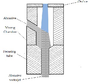
4000 bar. Fig. 1 shows the schematic of an abrasive injec- tion nozzle.
Fig.1 Abrasive injection nozzle
The machine is equipped with a gravity feed type of abra- sive hopper, an abrasive feeder system, a pneumatically controlled valve and a work piece table with dimension of 3000 mm x 1500 mm.
A 0.35 mm diameter sapphire orifice was used to transform the high-pressure water into a collimated jet, with a carbide nozzle of 1.05 mm diameter to form an abrasive waterjet. Throughout the experiments, the noz- zle was frequently checked and replaced with a new one whenever the nozzle was worn out significantly. The abrasives used were 80 mesh garnet particles with the average diameter of 0.18 mm and density of 4100 kg/m3. The abrasives were delivered using compressed air from a hopper to the mixing chamber and were regulated us- ing a metering disc. The abrasive waterjet pressure is ma- nually controlled using the pressure gauge. The standoff distance is controlled through the controller in the opera- tor control stand. The traverse speed was controlled au- tomatically by the abrasive waterjet system programmed by NC code. The debris of material and the slurry were collected into a catcher tank.
To achieve a thorough cut it was required that the combi- nations of the process variables give the jet enough ener- gy to penetrate through the specimens. The four variables in AWJC which was varied are as follows: water pressure
270 MPa to 400 MPa, nozzle traverse speed from 0.5 mm/s to 20 mm/s, standoff distance 1.8 mm to 5 mm and mass flow rate of abrasive particles from 8 g/s to 15 g/s. Read- ings were taken with various combinations of process parameters to gather the required data. Three different readings were taken at each sample and the average read- ings were calculated as to minimize the error.
By analysing the experimental data, it has been found that the effects of the four basic parameters, i.e., water pressure, abrasive mass flow rate, nozzle traverse speed and nozzle standoff distance on the depth of cut are in the same fashion as reported in previous studies for other materials [17], [18], [19], [20]. The effects each of these parameters is studied while keeping the other parameters considered in this study as constant.
The influence of water pressure on the depth of cut is shown in Fig. 2. Results indicate that, within the operat- ing range selected, increase of water pressure results in increase of depth of cut when mass flow rate, traverse speed and standoff distance were kept constant. When water pressure is increased, the jet kinetic energy increas- es that leads to more depth of cut.
IJSER © 2011
International Journal of Scientific & Engineering Research Volume 2, Issue 9, September-2011 3
ISSN 2229-5518
ma = 15 g/s
u = 0.5 mm/s s = 1.85 mm
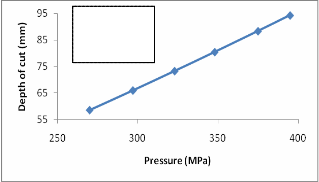
Fig.2 Water pressure versus depth of cut
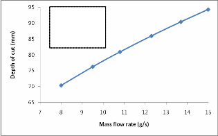
Increase in abrasive mass flow rate also increases the depth of cut as shown in Fig. 3. This is found while keep- ing the pressure, traverse speed and standoff distance as constant. The impact between the abrasive particle and the material determines the ability of the abrasive water- jet to cut the material. Since cutting is a cumulative process, the speed of the abrasive particle and the fre- quency of particle impacts are both important. The speed of the particle determines the impulsive loading on the material and the potential energy transfer from the par- ticle to the material. The frequency of the impact deter- mines the rate of energy transfer and hence, the rate of cut depth growth. The mass flow rate of the abrasive particles partially determines the frequency of the impacting par- ticles and partially determines the speed at which they hit. In addition, with the greater mass flow rates, the ki- netic energy of the water must be spread over more par- ticles. Therefore, the depth of cut goes down with the in- creased mass flow rate.
p = 395 MPa u = 0.5 mm/s s = 1.85 mm
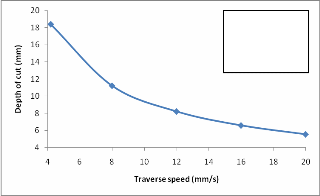
ing the other parameters considered in this study as con- stant. The longer the abrasive waterjet stays at a particu- lar location, the deeper the cut will be because the stream of abrasive particles has more time to erode the material. This effect is due to two reasons. First the longer the dwell time the greater the number of impacting abrasive particles hit the material and the greater the micro dam- age, which starts the erosion process. Secondly, the water from the jet does have a tendency to get into the micro cracks and because of the resulting hydrodynamic pres- sure, the crack growth results. When the micro cracks grow and connect, the included material will break loose from the parent material and the depth of cut increases. For this reason, it seems reasonable to expect an inverse relationship between the traverse speed and the depth of cut as shown in Fig. 4.
ma = 15 g/s
p = 395 MPa s = 1.85 mm
Fig.4 Nozzle traverse speed versus depth of cut
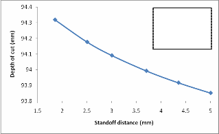
Standoff distance is the distance between the nozzle and the work piece during cutting operation If we keep other operational parameters constant, when standoff distance increases, depth of cut decreases. This is shown in Fig. 5. However standoff distance on depth of cut is not much influential when compared to the other parameters con- sidered in this study.
ma = 15 g/s
p = 395 MPa u = 0.5 mm/s
Fig.3 Abrasive mass flow rate versus depth of cut
Traverse speed is the advance rate of nozzle on horizon- tal plane per unit time during cutting operation. Results indicate that increase of traverse speed decreases the depth of cut within the operating range selected, by keep-
IJSER © 2011
Fig.5 Standoff distance versus depth of cut
International Journal of Scientific & Engineering Research Volume 2, Issue 9, September-2011 4
ISSN 2229-5518
To understand the effects of process parameters an empir- ical model is developed based on the experimental data set using regression analysis technique as shown in (1). This model relate the depth of cut to four process va- riables, namely water pressure, nozzle traverse speed, nozzle standoff distance and abrasive mass flow rate.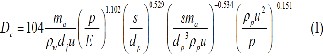
where Dc, dj, dp and s are in meters, ma is in kg/s, u is in m/s, ρp and ρw are in kg/m3, p and E are in MPa. The above model is valid for the operating parameters in the follow- ing range for practical purposes and machine limitations: Water pressure: 270 MPa ˂ p ˂ 400 MPa, nozzle traverse speed: 0.5 mm/s ˂ u ˂ 20 mm/s, standoff distance: 1.8 mm ˂ s ˂ 5 mm and abrasive mass flow rate: 8 g/s ˂ ma ˂
15 g/s.
To facilitate the understanding of the effect of the
process parameters, the above equation may be re-
arranged as in (2)![]()
For the material under consideration, it can be given as in
(3)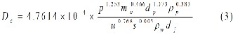
It has been shown that the above developed model (3) can adequately predict the depth of cut both qualitatively and quantitatively within the tested range of process pa- rameters in this study, with an average percentage devia- tion of less than 3%.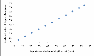
Fig.6 Comparision of experimental and predicted values depth of cut
There is a reasonable correlation between the experi- menttal and predicted values for depth of cut as shown in Fig. 6. Thus, it may be stated that the developed model can give adequate predictions for the depth of cut for the conditions considered in this study.
Dc depth of cut (mm)
ma mass flow rate of abrasive particles (g/s)
ρp density of particle (kg/m3)
ρw density of water (kg/m3)
dj diameter of jet (mm)
dp average diameter of particle (mm)
u traverse speed of nozzle (mm/s)
p water pressure (MPa)
E modulus of elasticity of material (MPa)
s standoff distance (mm)
In the present study experimental investigations have been carried for the depth of cut in abrasive waterjet cut- ting of cast iron. The effects of different operational pa- rameters such as: pressure, abrasive mass flow rate, tra- verse speed and nozzle standoff distance on depth of cut have been studied. As a result of this study, it is observed that these operational parameters have direct effect on depth of cut. Statistical regression analysis has been em- ployed to develop empirical model relating these process parameters to the depth of cut. The developed model is finally assessed using the experimental data and found to be able to give adequate predictions of the depth of cut with less than 3% of average deviations.
[1] Hascalik, A., Caydas, U., Gurun, H. “Effect of traverse speed on abrasive waterjet machining of Ti-6Al-4V al- loy”.Meter.Des.28: pp 1953-1957, 2007.
[2] Momber, A., Kovacevic, R. “Principles of Abrasive Waterjet
Machining”. Springer-Verlag, London, 1998.
[3] Hashish M. “A model for abrasive waterjet (AWJ) machining”.
Transactions of ASME Journal of Engineering Materials and
Technology, vol. III: pp 154-162, 1989.
[4] Siores E., Wong W C K., Chen L., Wager J G. “Enhancing abra- sive waterjet cutting of ceramics by head oscillation tech- niques”. Ann CIRP, 45[1]: pp 215-218, 1996.
[5] Wang J. “Abrasive Waterjet Machining of Engineering Mate- rials”. Uetikon-Zuerich [Swizerland]: Trans Tech Publications,
2003.
[6] M.A. Azmir, A.K. Ahsan. “Investigation on glass/epoxy compo- site surfaces machined by abrasive waterjet machining”. Jour- nal of Materials Processing Technology, vol.198, pp 122-128,
2008.
[7] C. Ma, R.T. Deam. “A correlation for predicting the kerf profile from abrasive waterjet cutting”. Experimental Thermal and Flu- id Science, vol.30, pp 337-343, 2006.
IJSER © 2011
International Journal of Scientific & Engineering Research Volume 2, Issue 9, September-2011 5
ISSN 2229-5518
[8] Kovacevic R. “Monitoring the depth of abrasive waterjet pene- tration”. International Journal of Machine Tools & Manufac- ture, vol 32(5), pp 725-736, 1992.
[9] Hashish, M. “Optimization factors in abrasive waterjet machin-
ing”. Transaction of ASME J. Eng. Ind. 113: pp 29-37, 1991.
[10] John Rozario Jegaraj J., Ramesh Babu N. "A soft computing approach for controlling the quality of cut with abrasive water- jet cutting system experiencing orifice and focusing tube wear", Journal of Materials Processing Technology, vol.185, no.1–3: pp 217–227, 2007.
[11] Shanmugam D. K., Wang J., Liu H. “Minimization of kerf ta- pers in abrasive waterjet machining of alumina ceramics using a compensation technique”. International Journal of Machine Tools and Manufacture 48: pp 1527–1534, 2008.
[12] Shanmugam D. K., Masood S. H. “An investigation of kerf characteristics in abrasive waterjet cutting of layered compo- sites”. International Journal of Material Processing Technology
209: pp 3887–3893, 2009.
[13] E. Lemma, L. Chen, E. Siores, J. Wang. “Optimising the AWJ cutting process of ductile materials using nozzle oscillation technique”. International Journal of Machine Tools and Manu- facture 42: pp 781–789, 2002.
[14] Wang J. “Predictive depth of jet penetration models for abra- sive waterjet cutting of alumina ceramics”. International Jour- nal of Mechanical Sciences 49: pp 306–316, 2007.
[15] Farhad Kolahan, Hamid Khajavi A. “A statistical approach for predicting and optimizing depth of cut in AWJ machining for
6063-T6 Al alloy”. World Academy of Science, Engineering and
Technology 59, 2009.
[16] Wang J. “A new model for the prediction depth of cut in abra- sive waterjet contouring of alumina ceramics”. Journal of ma- terial processing technology, 209: pp 2314-2320, 2009.
[17] M.Chithirai Pon Selvan, Dr. N. Mohana Sundara Raju. “An Experimental investigation on depth of cut in abrasive waterjet cutting of aluminium”. International Journal of Engineering Science and Technology, 3: pp 2950-2954, 2011.
[18] Wang J, Kuriyagawa T, Huang C Z. “An experimental study to enhance the cutting performance in abrasive waterjet machin- ing”. Machining Science & Technology, 7: pp 191-207, 2003.
[19] Wang J, Xu S. “Enhancing the AWJ cutting performance by
multi pass machining with controlled oscillation”. Key Engi- neering Materials, 291-292: pp 453-458, 2005.
[20] Shanmugam D. K., Masood S. H. “An investigation on kerf characteristics in abrasive waterjet cutting of layered compo- sites”. Journal of materials processing technology, 209: pp 3887-
3893. 2009.
IJSER © 2011