International Journal of Scientific & Engineering Research, Volume 3, Issue 2, February-2012 1
ISSN 2229-5518
Effect of Variation in Build-Up
Parameters on Noise Reduction in Automobile
Engine Silencers
S.O. Obayopo, M.O. Oyewola, O.O. Mojola, A.A. Asere
Abstract— The study focused on practical methods of reducing noise levels in automobile engine silencers. A comprehensive step to examine the flow pattern in relation to noise level generation, modify silencer parameters to effect noise level reduction is considered. The experimentation commenced with flow linearization process and this was followed by a design/build/test laboratory procedure t o ascertain the minimum noise level achievable by varying the inlet pipe size, resonating chamber length and the orifice size of the geometric build up of the silencers. Results from experimentation shows a reduction in noise level to the tune of 13.2dB (A) when comparison is made with the initial noise level of silencer used as the baseline level at 76.9dB (A). The results was incorporated to generate an optimum model for the
IC-engine (Volkswagen Passat Model) of 1921 cm3 engine capacity used as the test engine during the experimentation. Noise level in dB
(A) were depicted on noise level-time graph.
Index Terms— Automobile silencer, flow linearization, Geometric parameters, IC-engine, Noise level, Optimum model, World Health
Organisation (WHO)
1 INTRODUCTION
—————————— ——————————
Noise, popularly referred to as unwanted sound, is one of the serious and pressing environment problems in the world today. The World Health Organization (WHO) specifies 55 dB (A) as a hygienic guide value for the average level of noise in residential areas. However sound levels of around 70dB (A) are very common at the approaches to our towns and cities [1], [2]. Whether audible sound is annoying depends on the reaction of the receiver, a psychological factor as important as the noise source itself. Because people tend to judge a mechanical product’s quality by its ability to operate quietly, noise has become an increasingly serious problem in product design, in turn, engineering.
Traffic noise is the most important environmental noise source in the world today. Twenty-five percent of the populations in urban areas are exposed to transportation noise with an equivalent sound level of over 65db (A) [3], [4].
————————————————
Obayopo, S.O. - is currently pursuing PhD degree program in Mechanical Engineering in University of Pretoria, Pretoria South Africa, 0002. E-mail: sirajolanre@yahoo.com
Oyewola, M.O. , Associate Professor, Department of Mechanical Engineer- ing University of Ibadan, Ibadan Nigeria, E-mail:ooyewola@yahoo.com
Mojola, O.O. Professor, Department of Mechanical Engineering, Obafemi
Awolowo University, Ile-Ife, Osun State Nigeria.
Asere, A.A. Professor, Department of Mechanical Engineering, Obafemi
Awolowo University, Ile-Ife, Osun State Nigeria, E-
mail:aaasere77@yahoo.com
At this sound level sleep is seriously disturbed and most people become annoyed. To a vehicle designer, noise may be secondary to strength, durability and horse power output requirements. The consumer takes these for granted; to him noise is secondary only to job performance. Statistics today shows an increase in noise effect awareness by the populace and measures to abate the noise effects are on the increase.
According to an EPA (Environmental protection agency in United States of America) study¸ average noise levels in an urban environment are not hazardous to human hearing. Urban noise would be more appropriately classified as an annoyance resulting in interference with activity, particularly speech communication. However, medical reports on the effect of noise on man indicate that exposure to noise of 90db or higher for several hours can result in measurable hearing loss. Exposure to noise is revealed to individual not only in the form of hearing problems, but also in sleeping difficulties, high blood pressure and other health health hazards.
Public awareness on the need to control noise as an
environmental pollutant is increasing. According to United
Nations Environmental Program (UNEP), by the year 2000, it is
estimated that 4 out of 10 people in developing countries will live
in cities. While in 1990 there will be 66 housing more than four
million people, by 2025 there will be 135 such cities. These
statistics do not augur well for the future of the air that we must
breathe and level of noise that would be generated by vehicles in
those cities. Subsequently the effects on human health would be
severe if situation is not controlled.
Since traffic noise remain the most important
environmental noise source and generally in all transport
systems an Internal Combustion (IC) engines are employed,
IJSER © 2012
http://www.ijser.org
The research paper published by IJSER journal is about Effect of Variation in Build-Up Parameters on Noise Reduction in Automobile Engine Silencers 2
ISSN 2229-5518
exhaust and intake noise are major contributors to the overall noise pollution and need to be significantly reduced. In particular, reduction of noise from the exhaust is essential for reaching the pass-by noise targets. The pressing need to reduce noise pollution as well as air pollution will lead to increasing need of models for sound transmission and sound generation. Those models would incorporate the high flow velocities in engines exhaust and inlet systems, as an acoustic source. Sound transmission and generation in silencers and at the open ends of the exhaust will have to be improved or re- developed. This study investigates the effect of inlet pipe sizes, resonating chamber’s length and orifice sizes on the level of noise generation in automobile silencers as an insight to optimizing the reduction of noise from automobiles on our roads.
2 MATERIALS AND METHODS
2.1 Philosophy of Investigation
Models of selected types of silencers were tested in the smoke tunnel to investigate the aerodynamic flow pattern that accompanies the various models. Selection was based on the fact that some of the investigated silencers have similarities in term of geometric build-up and it was discovered that this are common to silencers of automobiles having close engine capacities. The aerodynamic flow pattern study is very useful as it assists to achieve some basic features that are required for an optimum modeling of silencers. Noise emanates as a result of the air flow turbulence. The basic requirement in the silencer design is to ensure a reduction in airflow turbulence [5], that are caused as a result of flow over baffle sections in the silencer duct, orifice along duct, changes of section, boundary layer turbulence and flow around corners (bends and take-offs). The objective is to investigate the models and select the one that will produce smoothest flow due to minimal turbulent flow features and subsequently reduces the generated noise level in the optimum model. The experiment was carried out by constructing models (distorted models) of different silencer sizes and varying parameters in order to study and understand the aerodynamic flow features. An assessment was made on the effect of varying the silencer geometry design parameters. These were in an attempt to determine the likely effect that the parameter manipulation could have on the level of attenuation of the designed silencers. Baja (1987) [6], suggests the following geometric parameters for an IC- engine of engine capacity between 1800 -2600 cm3 for silencer design,
Inlet-pipe size: 2.5-4.0 cm Orifice size: 0.26-0.34 cm Resonating chamber length: 12.0-13.2 cm
the final construction of the optimum silencer.
2.2 Equipment and Instrumentation
The various basic equipment used in the experimentation includes the digital camera, smoke tunnel, and IC-engine.
Digital camera: The digital camera is portable hand-held equipment basically employed during the investigation of various existing automobile exhaust system on Nigerian roads. Pictures of various models were taken after dissection to understand the muffler build-up mode and variations existing in the various models. The camera was also employed to picture the flow processes during flow visualization experiment in the smoke tunnel. This ensures proper documentation of resulting flow pattern from various models worked on in the smoke tunnel.
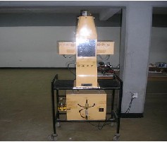
Smoke tunnel: The tunnel, which is made of sheet steel, was mounted vertically on light tubular steel trolley. The air flow was induced by means of a fan driven by a variable speed electric motor at the top of the tunnel. Air enters the base of the tunnel by way of a muslin strainer and is led through a contraction cone to the working section. The working section is 7 in wide x 9 ½ in high x 4 in. deep (182410 cm) and flow in it is vertically upwards. Models were attached to the rear wall of the working section while the front wall was made of Perspex (Lucite) and is readily removable. Smoke was introduced by a comb located below the working section which emits twenty-three streams of smoke at 0.275 in (7 mm) centers. The comb may be traversed from side to side to assist in the detailed exploration of the field of flow. The working section is brightly illuminated from both sides and the flow pattern is clearly visible.
Controls were available for the fan and a speed controller by means of which the speed of the fan and hence of the air flow in the working section may be varied from zero to about 10ft
/sec. (3 m sec-1). Models of silencer mufflers are attached to investigate the nature of flow pattern through the muffler section. Figure 1 shows the smoke tunnel used for the investigation.
IC-engine: The Internal Combustion (IC) engine used is a Volkswagen passat model engine with engine capacity of 1921 cm3.
This was used as the design guide for the experimenation
conducted in this study. The silencers orifice, resonating chamber length, and the inlet pipe variations were examined at this stage of the experiment. The assessment also guides in choosing appropriate sizing of the silencer geometry during
IJSER © 2012
http://www.ijser.org
Fig.1: A smoke tunnel
The research paper published by IJSER journal is about Effect of Variation in Build-Up Parameters on Noise Reduction in Automobile Engine Silencers 3
ISSN 2229-5518
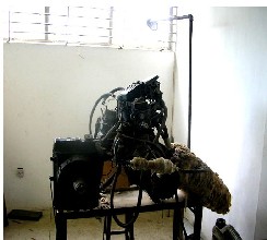
Fig. 2: Internal combustion engine (Volkswagen Passat model)
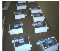
Fig. 3: Models constructed for smoke tunnel experiments
The product of combustion of the fuel and air mixture is used as the working fluid for power production. The used working fluid in the IC-engine is released to the atmosphere via the exhaust system. The engine is basically employed to carry out a quantitative testing of the prototype mufflers designed in order to ascertain the level of noise attenuation achieved. Fig. 2 shows the laboratory Volkswagen internal combustion engine used for the experimentation.
Noise meter: The noise meter is the Bruel and Kjaer Noise Dose meter-type 4436. It satisfies a wide range of noise exposure standards. It calculates, amongst other parameter, the sound exposure and the daily personal noise exposure level. The Type
4436 calculates the SPL (Sound pressure level) and Leq every second (sampling rate: 16 times a second). It has an internal microphone that serves most measurement purposes, with a level range of 55-140 dB and 90-143 dB (Peak). The instrument is employed to determine the level of noise attenuation achieved in the design.
Tachometer: The tachometer is a photo type employed in measuring the speed in revolution per minute (rpm) of the IC- engine. The meter has the capacity to measure rpm of wide
range and with high resolution. The rpm range span between
2.5 and 99,999 rpm. It also has accuracy of ± (0.05%+1 digit). The
measuring distance range is 50-500 mm. The maximum value of rpm at which the engine gives its maximum power was determined using the equipment.
Other instruments: The thickness of baffles and sizes of the orifices in the muffler are measured using the venire caliper. It has an accuracy of ±0.05 mm.
The length of mufflers sections (pipes, length, diameter of baffles) are taken using meter rules. This gives the accurate dimension of the muffler size during the preliminary study of common silencer designs and the constructed one.
2.3 Experimental Procedures
Description of location in which readings were taken: Each silencer was mounted on the IC-engine in the automobile workshop using gaskets between the exhaust manifold and the silencer and fastened together, to prevent leakage, with bolts and nuts. The exhaust manifold contains an exhaust port in the cylinder head, and a flat machined surface on this manifold fits against a matching surface on the exhaust port area in the cylinder head. The choice of measurement position was determined using Noise Measurement Manual [7], specifying the standards requirements for indoor and outdoor measurements. Measurements were taken at 1m from walls,
1.5 m above the floor and 1.5 m from the laboratory windows. Also other instruments in the laboratory were kept at 3 m away from the location of the mounted silencers.
Determination of the background sound pressure level: A preliminary set of experiments were performed to ascertain the existing background sound pressure level around the area of investigation. Noise levels of existing silencer models were measured and analyzed. This assists in formulating suitable experimental design for the stages of noise reduction process. The background sound pressure level or background noise level was obtained arithmetically by averaging the lowest levels of the ambient sound pressure level during interval of time “T”. Obtaining an accurate background sound pressure level is important, as it may be one of a number of criteria used to consider whether a noise from a source is reasonable. It also forms the basis of a reduction in noise emission levels to an acceptable level. The convention is to use the same measuring points selected for source noise measurement. This thus gives an acceptable representation to depict limits of noise levels.
The background noise level taken during the experiment was obtained initially in the absence of the silencer noise being investigated. The measurement was also taken at the quietest period of the night. These eliminate the possibility of intrusive noise from identifiable human activity or distant machine sources [8], [9]. Fifteen (15) minutes interval was chosen as interval for assessing the background noise and investigation was carried out for two hours.
Measurement and analysis of noise levels of existing silencer models: The determination of the extent of noise attenuation in the optimum model is best estimated by having
IJSER © 2012
http://www.ijser.org
The research paper published by IJSER journal is about Effect of Variation in Build-Up Parameters on Noise Reduction in Automobile Engine Silencers 4
ISSN 2229-5518
a baseline of what level of noise generation in the existing models offer and thereby giving room for comparison with the designed model. This will assist in determining area of modifications in the designed model after a qualitative testing of the level of noise generation with an IC- engine. The results from the existing silencers will give a guide in achieving the required optimum model specification for vehicles of varying engine capacities. A set of mufflers were thus constructed using some of the data obtained from investigation on silencer parameters, these were coupled with the IC- engine and set of measurements taken to determine the average noise level emanating from the system. Also, some imported units of similar silencers were used for comparison to give fair statistical results of the level of noise generated. These silencers were obtained from silencer sellers in automobile part center in Oyo State Nigeria and coupled with the IC- engine to ascertain the average level of noise generated from them.
Investigating the existing silencer geometric parameters: The main aim of this exercise is to investigate the design features of the existing silencer design models. This will give a clear picture of the varying parameters geometry such as the pipe sizing, orifice size, baffle thickness, muffler length as applied to various automobiles and the result will assist in specifying what values of these parameters would be fitting for the design that would give the required low noise model. A range of applicable parameters could thus be specified for certain types of vehicle engine capacities that are being designed.
A set of different types of reverse flow automobile silencers were collected and dissected to achieve the above stated objective. Various design component geometries were measured using vernier caliper and meter rules.
3 RESULTS AND DISCUSSION
Results of preliminary experiments: Table 1 shows the minimum, maximum and average ambient noise levels obtained at various points in the laboratory. The data shows that maximum ambient noise level occurred at point P3 with an average value of 57.3 dB (A). Also, the minimum ambient noise level was obtained at point P6 where the average value was 43.5 dB (A). Thus the background ambient noise level was fixed for the minimum value of 43.5 dB (A) to serve as the baseline for other measurements taken in the laboratory. The
(A) minimum to 88.2 dB(A) maximum levels.
The lowest noise level was observed on model 4 while model 5 gives the maximum noise level within the range of investigated five silencer models. The variation in noise level suggests that the geometry of the silencer models affects the noise level observed at the tail pipe of the exhaust silencer of the IC-engine. Thus, a further investigation into the flow regime in these geometries requires further experimentation to be able to depict the possible factors resulting in the variation of noise level in each silencer model.
Achieved noise levels through silencer parameter modification:
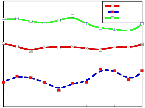
Effect of inlet-piping variation on design: Table 3 shows the dimensions of the silencers tested and Fig. 4 is a graph of noise level obtained for the 3 prototypes examined. The noise level as depicted on the graph shows that the best noise level was attained when the inlet pipe size is about 3.5 cm. At this level the minimum noise was observed to be 70 dB (A) and the maximum level 70.7 dB (A). At 4.0 cm, the level was not as significant as noise reduction was at 3.5 cm size. This shows that low noise level is better achieved by increasing the piping size from 3.0 cm. However increment beyond certain level (above 4.0 cm) does not show much noise reduction. Hence, inlet pipe size for the silencer model is best kept at 3.5 cm. Thus a 3.5 cm inlet pipe size was chosen for the optimum silencer prototype design.
Table 1: Background ambient noise level at 6 different locations in the laboratory

Noise level, dB (A)
--------------------------------------------------------------- Location Min Max Average

P1 53.2 54.5 53.9
P2 53.0 55.6 54.3
P3 56.5 58.0 57.3
P4 50.6 58.0 51.2
P5 49.2 50.2 49.7
P6 42.3 44.6 45.5

Table 2: Noise measurement on existing silencer design models (3m distance from tailpipe)
speed (rpm) of the engine, inlet pipe temperature and exit
temperature at measuring periods were 5.25103 rpm, 220 and
140° C, respectively. Table 2 shows the noise level of five different silencer units of different geometries investigated to ascertain the level of noise emanation from the existing
Parameters [cm] Level dB (A)
---------------------------------- -----------------------------------

Model IP OD RCL N1 N2 N3 Average

IJSER © 2012
http://www.ijser.org
The research paper published by IJSER journal is about Effect of Variation in Build-Up Parameters on Noise Reduction in Automobile Engine Silencers 5
ISSN 2229-5518
Table 3: The dimensions of silencers tested (varying the inlet- piping [cm])


Model ML MD PID OD BP RCL MPA 35 16 3.0 0.3 0.4 12.0
MPB 35 16 3.5 0.3 0.4 12.0
MPC 35 16 4.0 0.3 0.4 12.0


Table 4: The dimensions of the silencer tested (varying the resonating chambers length [cm])

Model ML MD PID OD BP RCL MRA 35 16 3.5 0.3 0.4 12.0
MRB 35 16 3.5 0.3 0.4 12.5
MRC 35 16 3.5 0.3 0.4 13.0

Table 5: The dimensions of the silencer tested (varying the orifice sizes [cm])


Model ML MD PID OD BP RCL MOA 35 16 3.5 0.28 0.4 12.5
MOB 35 16 3.5 0.30 0.4 12.5
MOC 35 16 3.5 0.32 0.4 12.5

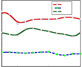
80
3.0 cm
3.5 cm
78 4.0 cm
76
74
72
70
68
10 20 30 40 50 60
Tim e (s)
the noise level considerably. The maximum and minimum level obtained at the 12.0 cm was 69.5 dB and 67.9 dB respectively. An attempt to increase the length from the reference length to 13.0 cm shows a sharp increase in noise level with a minimum value at 74.5dB. The results generally suggests that maintaining the resonating chamber length at a size not beyond the 12.0 cm length will definitely gives better noise level attenuation, and decreasing it excessively would prevent required pressure cancellation at the third chamber of the exhaust.
Effect of orifice variation on design: Table 5 shows the data used for the prototype model to verify the effect of the orifice variation. Also Fig. 6 shows the noise level at different time interval. In the graph, 0.28 cm size orifice along the pipes shows an outstanding noise level reduction compared to the other prototypes. An attempt to increase the orifice size to 0.3 cm size shows a reversal of effect as noise level observed at this level was averagely not different from the noise level when the orifice was at 0.32 cm. The minimum noise level obtained at the 0.28 cm orifice size was 70.7 dB (A) whereas the minimum noise level at both 0.3 cm and 0.32 cm was 76.4 dB. This result shows that orifice size at 0.28 cm will give the best combination to be incorporated in the optimum design model.
Result of treatment using sound absorbing materials: Three levels of fiber glass were incorporated at the last stage of the design work. The minimum noise levels obtained through the parameter variations examination in the first stage of the design were used as the optimum design parameter. Piping size of 3.5 cm, resonating chamber length of 12.0 cm and orifice size on pipe of 0. 28 cm. The fiber glass chosen was picked at 1.5,
2.0 and 2.5 cm thickness level to examine the effective noise
reduction that could be achieved using the property of the sound absorbing materials. These materials were incorporated in- between the silencer covering plates. Fig. 7 shows the graph depicting the noise levels offered by the 3-model silencers tested on the IC-engine. The graph shows that noise level decreases with increase in the thickness of the fiber glass. The minimum noise level was observed at 2.5 cm level of the absorbing material and the value measured was 63.7 dB (A) while the maximum noise level at this stage was 65.1 dB (A).

Table 6: Weight of silencer models with fiber glass
Fig. 4: Sound pressure level at varied inlet pipe diameters
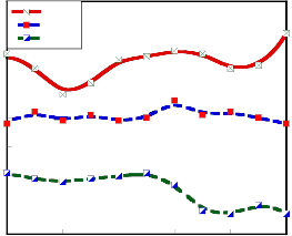
Effect of resonating chamber length variation on design: Table 4 shows the parameter used to investigate the effect resonating chamber length of the built models. Graphs of noise level in decibel were plotted against time interval as seen in Fig. 5 for the three prototype tested. The result of the test depicts the fact that reducing the resonating chamber length from 12.5 cm reference design length to 12.0 cm reduces
IJSER © 2012
http://www.ijser.org
The research paper published by IJSER journal is about Effect of Variation in Build-Up Parameters on Noise Reduction in Automobile Engine Silencers 6
ISSN 2229-5518
78
12.5 cm
12.0 cm
The thickness was chosen keeping in mind the required maximum weight of silencers for automobile. In designing
76
74
72
70
13.0 cm
silencer for an average car, weight was suggested to be maintained at 23 kg maximum value [10].This will reduce the weight of the vehicle and subsequently reduce horse power requirement. Table 6 shows the weights of the optimum models with incorporated fiber glass material after construction. In the design, weight is considered to be an important factor hence the need to limit the silencer weight to minimum level to avoid excessive weight of the silencer model which will invariably affect the load on the vehicle.
68
66
10 20 30 40 50 60
Time (s)
Fig. 5: Sound pressure level at varied resonating chamber length

80
0.32 cm
0.28 cm
0.30 cm
78
76
74
72
4 CONCLUSION
Effect of variation in build-up parameters on noise reduction in automobile engine silencers has been investigated. The results showed that aerodynamic noise in automobile silencers is a function of flow turbulence in the silencer compartment. Flow linearization through design/build/test experiment can considerably reduce noise level generation in automobile silencers and subsequently, improve the performance of the silencer. Silencer parameters such as inlet-pipe size, orifice size, resonating chamber length affects the silencer performance. Appropriate absorbing material thickness also reduce noise generation from silencers. A reduction in the noise level to the tune of 13.2 dB (A) when comparison is made with the initial noise level of silencer used as the baseline level at 76.9dB (A) was achieved in this study. The results was incorporated to generate an optimum model for the IC-engine (Volkswagen, Passat Model) of 1921cm3 engine capacity used as the test engine during the experimentation.
NOMENCLATURE
70
10 20 30 40 50 60
Time (s)
Fig. 6: Sound pressure level at varied orifice sizes
71
1.5 cm
70 2.0 cm
2.5 cm
69
68
67
66
65
64
63
10 20 30 40 50 60
Time (s)
Fig. 7: Sound pressure level at varied thickness of absorbing materials
ACKNOWLEDGMENT
The authors wish to thank the technical staff of the depart- ment of Mechanical Engineering, Obafemi Awolowo Universi- ty, Ile-Ife Nigeria for their support during the study.
REFERENCES
[1] Simmonsson, B., 1998. Noise abatement programme in urban settlements. Swedish Energy Technol. J., 3: 13-15.
[2] Cornel, E.D., 2004. Effect of Noise on Ambient Environment. Acoustic
J., 48: 18-28.
IJSER © 2012
http://www.ijser.org
The research paper published by IJSER journal is about Effect of Variation in Build-Up Parameters on Noise Reduction in Automobile Engine Silencers 7
ISSN 2229-5518
[3] Cherry, P., 2003. Noise in Construction Equipment. 2nd Ed. Prentice
Hall, London.
[4] Crooker, M.J., 1995. Fundamentals of control of noise and vibration.
Purdue Short-course Reduction Machinery Noise. pp: 12-14.
[5] Marian, P., 2005. Noise suppressor for the textile industry. Fibres
Textiles Eastern Eur., 13: 80-84.
[6] Baja, V.M. 1987. Automobile exhaust silencer design for mini vehicles.
Design Construction Report. Baja Exhaust inc. United Kingdom. (http://www.bajaexhaust.net/exhaust.design.htm, 19/07/2005).
[7] Queensland, J., 2000. United nations noise pollution regulation. Eur.
Commun. Noise Pollution Official J., 42: 22-24.
[8] Bruel, K., 2004. Environmental Noise Measurement, 2nd Ed. Naerum
Ltd., Denmark. Campbell, J.S. The Basic Terminology of Noise. J. Machine Design 35: 140-158.
[9] Bjare, T., 1998. Noise and the environment. Swedish Energy
Technology J. 1: 8- 9.
[10] Mugen, A.R., 2002. Noise reduction of Gasoline and Diesel Engines, in the relations between noise and basic structural vibration of engines.
J. Society Automobile Eng. Inc., 6904: 16-31.
IJSER © 2012
http://www.ijser.org