International Journal of Scientific & Engineering Research Volume 4, Issue 1, January-2013 1
ISSN 2229-5518
EARLY DETECTION & ALARMING OF A TRANSVERSE CRACK IN A RAILWAY TRACK (MODIFIED)
R.V.K. Charan
Department of Physics, Gaya College, Gaya, Bihar, India – 823001
E.mail- rvkcharan@rediffmail.com
Abstract : A train moving on tracks may meet an accident causing huge loss of property and innocent lives if there appears a defect of crack /gap/breakage or a loose fish plating in the continuity of either of the tracks. The defect of crack may be longitudinal or transverse. But the transverse crack or loose fish plating is more fatal. Hence, to detect such defects a theory along with a circuit is developed here on basis of phase cancellation and by application of series resonant circuit for facilitating a railway station master to signal the incoming train to stop accordingly through alarm and indicating bulbes to stop to avert an accident.
1.Introduction : A train runs on a pair of tracks which are mounted on ground with support of iron or cement sleepers (containing iron in its RCC mould) connecting i.e. short circuiting the tracks at regular intervals. So, if the tracks are fed with a.c. or d.c. directly they behave as a single conducting wire and thus it becomes quite difficult to detect a defect in either of the tracks independently. The defect of crack may be longitudinal or transverse or a loose fish plating but the latter two are more fatal. Hence, the first problem is to separate the two tracks electrically independent to check them independently and then the second problem is to place them into two independent circuits to convert the corresponding output electrical signal into an alarm to signal the station master accordingly to stop the advancing train if there appears a crack in either of the track as this will lead to a serious train accident causing huge loss of innocent lives and property.
To detect such defects magnetic methods were earlier used1, 2, but it was affected by environmental magnetic noise and inadequate sensitivity. Clark3 used contact ultrasonic, but the ultrasonic beam could not reach internal defects due to horizontal surface cracks, and, moreover, it suffered from a limited inspection speed. Researchers in US patent4, 2001 invented a theory of enrooting electromagnetic flux through axles of wheels which when encountered with such transverse cracks changes the flux pattern to enable to find its location for immediate braking. But it may overturn the speeding train as it lacks early detection and alarming technique. Scalea et al5 used guided pulsed laser beam along with air-coupled sensor for earlier detection of the size and location of the transverse crack in their non-contact method successfully.
The present study is a step forward to detect and to alarm earlier i.e. before passing of train, of such defect of transverse cracks or even of a loose fish plating on basis of “Phase cancellation theory” and by application of “series resonant circuit”. It has got two important advantages over the author’s earlier work6 in using parallel resonance circuit that there is now no need of measuring tracks’ effective resistance parameter created due to the applied high frequency alternating current into the tracks for` calculating resonant frequency ,and secondly, the circuit gets a higher current at resonance for its better detection and working. However, such effective resistance will lower down the circuit current but it can be set accordingly by choosing a source of appropriate ampere strength.
2. Phase cancellation Theory : A theory is developed here to separate electrically the two tracks short circuited by iron or cement sleepers at regular intervals, as stated above. According IJSER © 2013
http://www.ijser.org
International Journal of Scientific & Engineering Research Volume 4, Issue 1, January-2013 2
ISSN 2229-5518
to it, if the two tracks are fed with two independent sine waves generated from two coherent
sources S
and S
in such a manner that their frequencies and amplitudes remain the same, but their
phases are set to 1800 out, and, further if the inter- track separation i.e. if the effective length of a sleeper is half of a wave length i.e 'A /2, then the trough of one wave will
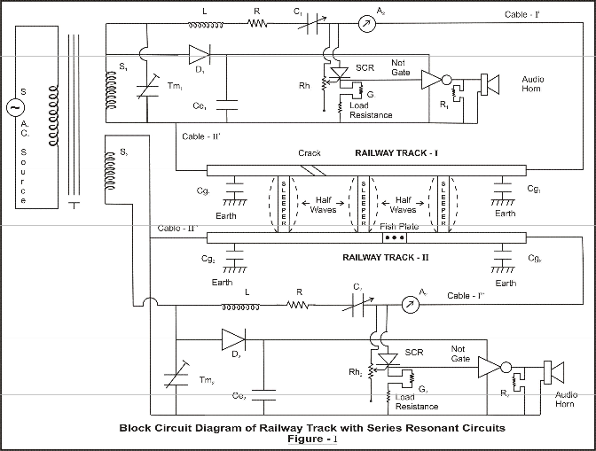
fall on the crest of other wave across each sleeper during the whole path, resulting in their automatic cancellation. However, this phase cancellation will not load down the impedances of the sources, as they are independent, but rather cancel the effect of one track to cross over to another. Hence, the defect of any transverse crack /gap/breakage or a loose fish plating appearing in the continuity of one track shall reduce the preset resonant frequency of the corresponding circuit only and not that of the other circuit attached to another circuit. This phenomenon can be well understood by a block diagram of the circuit containing wave-representation in fig.- 1 below along with the circuit description as follows.
Now, since the two sine waves are 1800 out of phase, as stated above, the instant E.M.F. of the progressive waves at any instant across the tracks (Fig.-1) can be given as,
E = E
Sine ( mt + K x )………………………………………. (i)
and E
= E Sine ( mt + K x + n )………………………………….(ii)
IJSER © 2013 http://www.ijser.org
International Journal of Scientific & Engineering Research Volume 4, Issue 1, January-2013 3
ISSN 2229-5518
Where E
is the maximum e.m.f. , m is angular frequency, t is time, K is wave number
equal to 2 n / 'A and x is the instant distance.
Therefore, the total E.M.F.s due to both waves across the tracks at any instant become as,
E= E
+ E = E
Sine (m t + K x) - E
Sine (mt + K x) = 0 ………………(iii)
Hence, no E.M.F. will be produced across the tracks i.e. across the sleepers because the trough & crest (of length 'A/2) of each other wave falling on each other will automatically cancel each other effect according to the aforesaid principle of phase cancellation ,and this will in turn bar one wave’s effect to cross over to another. Further, as the conductance and impedance of the ground bearing the tracks depends mainly upon its humidity and the chemicals present in it will be also nullified automatically according to the aforesaid principle of phase cancellation.
3.Circuit Descriptio n:-Before analyzing the circuit for resonance it is necessary to present a brief description of the circuit drawn in figure-1.It represents a block diagram of two equivalent series resonant L-R-C circuits(capacitor tuned) which are powered by two coherent sine wave sources S1 and S2 taken from a same source S through a transformer T. The sources S1 and S2 are injected into the corresponding tacks-I and II through the circuits in such a manner that the phase of one is inversed with other in order to maintain the aforesaid phase cancellation condition by 180 degree out of each other. The other parameters remain same because of the coherency of the source. The L and R are common circuit inductors and resistances where as C1 and C2 are variable capacitors to tune the circuits for resonance. The Tm1 and Tm2 are fine adjustable capacitor trimmers for fine tuning of the sources. The audio horns I and II of the circuits are powered by silicon control rectifiers(SCR) via NOT logic gates. The SCRs are set for conduction through the rheostat Rh1 and Rh2 at the maximum peak resonant current at resonance without considering any defect along the tracks .The output of the SCRs are then inversed by the NOT logic gate operation giving no output at an input. The NOT logic gates are powered by independent a.c. to d.c. converter unit (comprising of Diodes D1 & D2 and capacitors Ce1 &Ce2) directly through the source. The A1 and A2 are ammeters to observe the resonant current where as G1 & G2 and R1 & R2 are respectively green and red indicating bulbs for observing conduction of SCR and NOT logic gates directing the horns to be OFF and ONN. The grounded capacitors Cg1 & Cg2 are attached to the tracks at certain regular intervals to minimize the effect of interference created due to radio waves radiating out of the tracks due to very high frequency currents. The overhead cables I’ & II’ and I” &II’’ of the circuits are clamped at the required ends of the tracks under testing. The dotted wave type lines across sleepers show wave formation along the tracks showing the phase cancellation process.
4. Analysis of Circuit : The sources S
& S with which the tracks are fed for making them
electrically independent power the two corresponding series resonant circuits (Fig.- 1). But before analyzing the series resonant circuits, an another theory is established, here, to treat a transverse crack or a gap or a breakage or even a loose fish plating which creates even fine or large defect of discontinuity in the continuity of a track as an almost parallel plate capacitor, herein called as
‘crack capacitor’. This is because in a.c. the current tends to concentrate on the outer layers of the material i.e. affecting the material from outside, mostly due to skin effect7 and so any transverse crack in the surface immediately forms almost an effective parallel plate capacitor.
Now, since the two separate series resonant circuits have equal parameters of resistance R
and inductance L with tuned capacitances of C1 & C2 of reactances Xc’ and Xc’’, the e.m.f. of
IJSER © 2013 http://www.ijser.org
International Journal of Scientific & Engineering Research Volume 4, Issue 1, January-2013 4
ISSN 2229-5518
such circuits containing the defects of aforesaid crack capacitor can be expressed by analyzing the equivalent circuit as shown in fig.-2 below as8,
E = I
[R + R' + J {X’
- (X'
+ X'
)}] —————————————— (iv)
1 1 t
L C Ct
And, E
= I [R + R" + J {X’’
- (X''
+ X"
)}] ————————————— (v)
2 2 t
L C Ct
where I
and I
are currents, R'
and R"
are track effective resistances, and, X’L & X’’L and
& X’’
are the reactances of circuit inductors and of the so called 'crack capacitors’ of the
tracks 1 & 2 respectively.
IJSER © 2013 http://www.ijser.org
International Journal of Scientific & Engineering Research Volume 4, Issue 1, January-2013 5
ISSN 2229-5518
L R
R't
R"t
L R
Equivalent Track Circuit With Series Resonances
Figure- 2
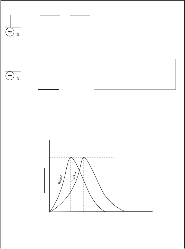
Max
Resonance Resonance
Frequency
Current-Frequency Curve Showing maxm current At Resonance
Figure- 3
International Journal of Scientific & Engineering Research Volume 4, Issue 1, January-2013 6
ISSN 2229-5518
Now, the circuits for the tracks are tuned at resonance for maximum current by use of the series tuner capacitors C1 & C2 where the resonance is defined as an operation of the reactive part at unity power factor i.e. the reactive terms must be zero. Accordingly the equations (iv) and (v) yield as,
X’ = X’
+ X’'
, and X’’
= X’’ + X’’
————————— (vi)
Now, by substituting the values of X’
as 2n f' L, X"
as 2 n f"
L, X'
as 1/2n f'
C, X" as
1/2n f"
C, X'
as 1/2n f' C’
and X"
as ½ n f"
C" in eq. (vii) the resonant frequencies of the two
r ct
r t ct r t
resonant circuits involving the defect of so called ‘crack capacitor’ in the continuity of the tracks are given as, .


' 1 & f " - 1
rt ' rt "
---------------------------------- (vii)
2n L(C + Ct )
2n L(C + Ct )
Now, as per definition since value of a parallel plate capacitor is equal to the its plate cross sectional area multiplied by the dielectric constant of the inside medium and then divided by the separation of its plates , and as the cross sectional area and the dielectric constant of the inside medium remain constant for a certain track and medium, the value of the ‘crack capacitor’ along either of the tracks will inversely depend upon the separation of the crack gap only. Therefore, as from eq. (vii) above, the resonant frequency will directly depend upon the plate gap created in the
‘crack capacitor’. So, larger the plate gap inside the ‘crack capacitor’ higher will be the resonant frequency. But after a threshold limit of plate separation inside the crack gap there shall be no capacitive effect and the resonance will cease and there will be wider discontinuity. However,. the resonant frequency will change by the abovementioned relation in eq.(vii) at any state, in case of a crack the preset SCR will get permanently imbalanced due to changed current in the circuit and thereby will stop its conductive output which in turn will trigger the NOT logic gate to conduct for ringing the audio alarm horn.
But, if there are no such defects in the tracks, i.e. the tracks are continuous then the track
capacitances C'
& C"
vanish and the the aforesaid resonant frequencies reach their maximum
natural values bearing the maximum e.m.f. , E
= E2 = E0 with9,

f ' - f " - 1
r r 2n LC
---------------------------------- (viii)
This is the resonant frequency of a series resonant circuits and is clearly devoid of any resistance parameters, as said above. Thus it is obvious that for the resonant frequencies there shall be no need of calculating any resistance parameter. The circuits’ currents carrying the defect of so called crack capacitors in the continuity of the track yield from the eqs. (iv) and (v) as,
I E1

1 - '
' ' '
------------------------------- (ix)
(R + R t ) + {XL (Xc + Xct )}
I2 -

E 2
(R + R " ) + {X" (X" + X" )}
---------------------------------- (x)
t L c ct
But if there is no defects in the continuity of the tacks i.e. the tracks are continuous, then, at resonance where the reactive parts become zero, the values of resonant currents reach their maximum (as shown in fig.3 above) by yielding as,
IJSER © 2013 http://www.ijser.org
International Journal of Scientific & Engineering Research Volume 4, Issue 1, January-2013 7
ISSN 2229-5518

I' - E1

and I" - E2
---------------------------------- (xi)
r R + R ' r
R + R "
Now for a certain condition at maximum emf , where Sine (mt + Kx) = 1 at R'
= R"
= Rt
(Say), the currents reach their maximum value i.e. I'
= I" = E
/ R+Rt
,i.e. the maximum current
without any defect in the tracks.
5. Design of circuit parameters;-For designing the circuit parameters of inductance L and the variable capacitors C1 and C2 it is necessary to to find a required resonant frequency ‘f’ for a given inter-track separation by substituting the wavelength 'A as twice of the track separation to facilitate the aforediscussed phase cancellation process, by the relation,
C = f. 'A ..................................................(xii)
where ‘C’ is the velocity of electrical wave which is taken as equal to the velocity of light as 3*108
metre/second roughly .
After finding the required resonant frequency the values of L,C1 & C2 are then found out by the aforementioned relation--(viii).The resistance parameters are so chosen to get the appreciable current in the circuit to fire the SCR (so chosen).
6.Operation:-After clamping the overhead cables I’ & II’ and I’’ & II’’ to the required ends of the track( under testing) the two series resonant circuits are tuned for resonance through the variable capacitors C1 & C2 by maintaining no defects along the tracks. At the resonance the circuits’ currents reach the maximum peak values and the SCRs are set for conduction through the rheostat Rh1 & Rh2 for the values. The reasonable working current in the SCR is obtained by chosing the source of appropriate ampere strength. The conducting current of SCRs will not trigger the the audio horns to start to alarm due to inverse operation of NOT logic gates which sends no output at an input and an output at no input. Now as soon as there appears an aforesaid defect of transverse crack or even a loose fish plating along either of the tracks owing to any metallic aberration/sabotage only the corresponding resonant circuit (due to aforesaid phase cancellation process) gets imbalanced due to receding resonant current which in turn stops conduction of the corresponding preset SCR .The non- conduction of the SCR triggers the corresponding NOT logic gates to send a current signal to the corresponding horn to alarm with illumination of the red bulb exhibiting a danger zone for the incoming train. So the station master will signal the incoming train only after observing of no alarm and no red bulb illumination. But even after giving a proper signal to the incoming trainwith no defects the alarm starts due to sudden creation of crack then also the alarm signal can be transmitted to the driver of the moving train through mobile-radio-networking system to stop its advancement. A computer software system can be attached to the circuit to monitor the alarming and non-alarming states. By this process so many innocent lives can be saved from accident at least due to such transverse defects along tracks
7.Experiment:- A prototype experiment was performed after setting the aforesaid circuit parameters for a railway track of length of one kilometer and the circuits were tuned for resonance by varying the tuner capacitors C1 & C2 without having even a finest transverse crack or loose fish plating along the tracks. At resonance the circuit currents were maximum i.e. about 500 mA (as set earlierly) and the SCR were set for conduction and the green bulb were illuminated .But the NOT logic gates attached after the SCR did not send any current to the audio horn to alarm. This is the right condition to allow the train to come in. But, as soon as even a finest crack or loose fish plating was made along either of the track developing a parallel plate capacitor ,the preset resonances got imbalanced and the circuit current started receding which in turn stopped the conduction of the SCR
.The non-conduction of the SCR triggered the NOT logic gate to send a current signal to the red
IJSER © 2013 http://www.ijser.org
International Journal of Scientific & Engineering Research Volume 4, Issue 1, January-2013 8
ISSN 2229-5518
signaling bulb as well as to the audio horn to alarm for a danger zone for the incoming train. Thus, the station master signaled the incoming train to stop after monitoring the bulbs and the alarm
In the experiment the following datas were computed as per the Indian Broad Gauge Railway specifications:
Sleeper thickness = 180mm,Intertrack separation = 1.676 metre,i.e.the twice of inter track separation=3.352 metres,Resonant frequency=895 mc/s. With these specifications the values of inductor L, C1& C2 were designed as L=10 nH,C1 & C2=316pf.But practically for fine adjustment L was taken as 5-20 nH and C1 & C2 =250-350 pf.
The values of circuit d.c.resistance R is so chosen to get the appreciable current of about 500 mA strength in the SCR for its setting for firing after overcoming the potential drop across the total length of the track containing the inductive resistance due to the skin effect occurring in a.c.The value of the effective resistance R1 is calculated by the famous Rayleigh relation 7which is simplified as,
R1 =a/a * ( i f µ )1/2 ……………………………………………..(xiii)
where the length of the track ‘a’ is kept as one kilometer, the equivalent cross sectional radius ‘a’ of the track as 0.473 meter, the specific resistance ‘ i ‘ for iron as 10*10 - 8 ohm- meter and ‘ µ’ is the permeability.
8..Co nclu sio n:-The aforesaid circuit is best suited to avert a train accident occurring due to defect of a transverse crack or loose fish plating along either of the track owing to any metallic aberration or sabotage for early detection and alarming. But the circuit has certain limitations:-
(i)A partial transverse crack may not be successful in unbalancing the resonance and thereby resulting in non ringing of the alarm. There shall be an alarm only if the defect is 100 percent across the cross sectional area of the track.
(ii)Owing to the very high frequency of the resonant wave i.e. of the order of megacycle range as the skin effect becomes more prominent ,the effective resistance becomes too higher resulting in much potential drop. So the circuit is suited for only track of small length of about 3-5
Km. For larger length of about 10 Km between two consecutive stations the circuit arrangement is to be repeated successively for better result or the source of higher energy is to be chosen for better
result.
9.Acknowledgement: - The author expresses his sincere gratitude to the libraries of Magadh University, Bodh-Gaya and Gaya College, Gaya ,Bihar, INDIA for the study . His gratitude further extends to the international search website of Google.com for facilitating the international overview of researches and also to Dr. A.K. Verma of the Department of Physics of Gaya College, Gaya, Bihar, INDIA for contributing to knowledge and inspiring all the time.
References :
1. Oukheloou L. et al, ‘Dedicated Sensor and classifier of Rail Head Defects, Control
Engineering Practice, Vol. 7, pp 57-61, 1999, U.S.A.
IJSER © 2013 http://www.ijser.org
International Journal of Scientific & Engineering Research Volume 4, Issue 1, January-2013 9
ISSN 2229-5518
2. Pohl R.et al, ‘NDT Techniques for Railroad wheel and Gauge Corner Inspection’ , NDT&E International, vol. 37pp 89-94, 2004, U.S.A.
3. Clark R, ‘Rail Flaw Detection: Overview and Needs for Future Developments’ , NDT & E International, Vol. 37, pp 111-118, 2004, U.S.A.
4. U.S patent no. 6262573, Electromagnetic system for railroad track crack detection and traction enhancement,validity-17 July, 2001 to 17 Sep. 2019,U.S.A.
5. Scalea F. L. Di. et al, ‘Non-contact ultrasonic inspection of rails and signal processing for automatic defect detection and classification' NDT in Rail industry, Vol. 47 NO. 6, June
2005 U.S.A..
6. Charan R.V.K. , ‘Early Detection and Alarming of Any crack In a Railway Track’, Acta
Ciencia Indica, Meerut, India, Vol. XXXI P. NO. 2, 145, (2005) India.
7. Starling S.G., “Electricity and Magentism’ , 8th edition, pp- 364 First Printed in India.
8. Ryder J.D., Network lines and field, 2nd edition, Michigan State University,. pp-58 U.S.A.
9. Gupta and Kumar, A Handbook of Electronics, 12th edition, pp- 10 ,India.
* * ** * * *
IJSER © 2013 http://www.ijser.org