
Experimental and analytical studies by Benjamin and
Williams [23]show that centrally located openings may
International Journal of Scientific & Engineering Research, Volume 6, Issue 3, March-2015 136
ISSN 2229-5518
Development of a Modified One-Strut Design Model for Shear Strength of Masonry Infilled Frames with Opening
* M. E. Ephraim and ** T.C. Nwofor
*Department of Civil Engineering, Rivers State University of Science and Technology
P.M.B 5080 Port Harcourt, Rivers State, Nigeria.
**Department of Civil Engineering, University of Port Harcourt, P.M.B 5323 Port Harcourt, Rivers State, Nigeria.
—————————— ——————————
he recent trend of building construction is characterized by massive application of reinforced concrete frames, infilled with walls for load bearing
or partitioning purposes. In multistory frames, shear walls are used as bracing elements. These infill walls are usually structural masonry, made up of concrete or burnt clay bricks, bonded together in cement mortar. Structural masonry was traditionally widely used in civil and structural engineering works including buildings, tunnels, bridges, aqueducts, retaining walls, sewerage systems among others. At present, there has been growing interest by researchers to relate masonry work design to its actual behavior which has reflected in the increased research in this area [1-6].
From the first attempts to model the response of composite infilled frame structures, experimental and conceptual studies have suggested that a diagonal strut with the appropriate geometrical and material characteristics could be used to represent the composite action of an infilled frame. Several investigators [7-15] have proposed variations of the equivalent strut model, with the key parameter being the effective width of the strut. Polyakov [16], first studied the possibility of considering the effect of the infill panel as equivalent to diagonal bracing and this suggestion was later taken up by Holmes [7], who replaced
the infill by an equivalent pin-jointed diagonal strut, made of the same material and having the same thickness as the infill panel and a width equal to one third of the infill diagonal length. Some other researchers related the width of the equivalent diagonal strut to the infill/frame contact lengths using an analytical solution, adapted from the equation of beam on an elastic foundation, subjected to a concentrated load.
Holmes [7] suggested that the effective width of an equivalent strut depends primarily upon the thickness and aspect ratio of the infill. Stafford-Smith and Carter [17] have posited that the equivalent strut width is not a constant value, but varies with the applied loading and the relative properties of the frame and infill. However, Mehrabiet al. [18] found that the lateral stiffness of the infilled frames using Stafford-Smith and Carter’s equivalent struts is consistently underestimated by a factor of two when the bending stiffness for uncracked RC sections is used. Further attempts to capture the interaction of in-plane and out-of- plane strength under bi-directional loading have resulted in the introduction of three-strut and multiple-strut models [12], [15], [19], [20], [21], [22].
Infill walls in frames frequently contain door and window openings at the different locations, which naturally reduces stiffness and load carrying capacity of the diagonal strut depending upon the size of opening and its location.
IJSER © 2015 http://www.ijser.org
International Journal of Scientific & Engineering Research, Volume 6, Issue 3, March-2015 137
ISSN 2229-5518
Experimental and analytical studies by Benjamin and
Williams [23]show that centrally located openings may
detachment
Contact stress distribution
Idealized stress distribution
reduce the stiffness and strength of diagonal strut by about
75% and 40% respectively. In spite of these facts, most researches have tended to concentrate on simple cases of infill wall without openings. Analytical study of infill frame with openings is limited and has little comparison due to the differences in the type of materials used and openings considered.![]()
![]()
z
h
h hw
detachment frame-infill
frame-infill
L
d w
e
![]()
Lw
L
L
Stress
h distribution
for effective strut
h Effective
diagonal
strut width, w/2 thickness, t
L
From the above, it can be seen that the consideration of the
infill panel in the design of RC frame structures results in a complex modeling problem because of the large number of interacting parameters and the many possible modes of failure that need to be evaluated with a high degree of uncertainty. The need to obtain deeper understanding of the influence of openings on the composite behavior of infilled frames has further led to development of more and more complex models with ever increasing number of parameters. An experimental study in which all these factors could be taken into account is difficult to implement for obvious reasons. Thus, in most cases the use of finite
(c) Deformed Assemblage (d) Deformed Assemblage with
Stress Distribution
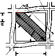
Studies by Hendry [16] have shown that the geometric
properties of the diagonal strut are functions of the length of contact α h and α L between the wall and the column and the beam respectively (Figure 1). Hence, assuming a beam on elastic foundation, the following expressions are obtained for the contact lengths [17]:
element approach has been considered a most viable option
in spite its computational complexities and resource![]()
α π 4
4E f
I c h
![]()
h = (1)
requirements. For these reasons, the need for more simplified models of the composite behavior of infilled frame has been recognized by researchers. In this paper, a single diagonal strut model, capable of predicting the shear
strength response of infilled frames with openings is![]()
2
α L = π 4
E m tSin 2θ
4E f I b L Em tSin 2θ
(2)
presented. A unique feature, enhancing the efficiency of the model, is the introduction of a strength reduction factor, developed by the authors in the study.
Experimental evidence have shown that under racky loads, the infill tends to separate at the unloaded corners while
maintaining clearly defined contact zones with the frame at the loaded corners. Diagonal cracks are observed along the compression diagonal. This lends credence to the
assumption that the infill panel could be replaced by an equivalent pin-jointed diagonal compression strut of the
Where E m, Ef = elastic moduli of the masonry wall
and frame material respectively.
Also from Figure 1, assuming a triangular stress distribution along the width of strut w, the force in the strut is 1/ 2 fm wt, where the average compressive stress is one-half of the maximum stress fm.
Using the Pythogoras equation, the effective strut width of
infill without opening equals
same material and having the same thickness as the infill
panel. The mechanism of response of a typical infilled![]()
w = c h
(3)
frame is shown in Figure 1.![]()
moment frame
h
masonry infill panel
L

frame element
![]()
L
![]()
The shear bracing capacity of the strut will be reduced by the presence of openings by a factor which will depend on the opening ratio (β), expressed as the ratio of the opening
h area to the area of the solid infill panel. Now, assuming wo is the effective width of the diagonal strut with opening and fm the compressive strength of the masonry, the infill
strength reduction factor can be obtained as follows.
Resistance of solid infill R = 1/2 fm wt = 1/2 fm A
(a) Infilled Frame (b) One-Strut Model
Resistance of infill with opening
IJSER © 2015 http://www.ijser.org
International Journal of Scientific & Engineering Research, Volume 6, Issue 3, March-2015 138
ISSN 2229-5518
Ro = 1/2 fm wot = 1/ 2fm Am
Stress reduction factor due to openings
The equilibrium equation takes the form
λm = Ro/R = Am/A

P k11( AC ) 0
![]()

k12( AC ) 0 d
A A
Hence
0 k + k k k
Ao = λm A (4)
PB =
11( BD)
11( BC )
12( BC )
12( BD) dB
(7)
In order to modify the equivalent diagonal area to account
PC k21( AC )
k21( BC )
k22( AC ) + k22( BC ) + k11(CD)
k12(CD) dC
PD 0
for openings, a suitable equation was obtained by regression
analysis on data obtained from previous experimental and
k21( BD)
k21(CD)
k22(CD) + k22( BD) dD
analytical works by the authors, where the shear strength reduction factor (λm) was related to the opening ratio (β) of the infill panel in the form
The component stiffness matrix for the pin-jointed diagonal
strut BC, is given by
λ m =
e0.06 β
(5)
[k ] =
![]()
EAm
l 2 lm
2
m
− l 2
− lm
− lm
− m 2
out using the stiffness matrix method in which the diagonal
L l 2
Symmetrical
lm
m 2
(8)
strut is modeled as a pin-jointed bar element while the frame members were modeled as rigid jointed members. Analyzing the equivalent frame using classical methods of structural analysis in the matrix stiffness method for a frame structure, maximum unknown horizontal deflections were obtained from the solution of the global structural matrix where the force vector and the displacement vector was
Where E and Am represents the elastic modulus of masonry
and modified area respectively.
The component stiffness matrices for the plane frame elements AC, CD and BD were obtained using the general stiffness matrix equation. For example the transformed element stiffness k11 equals
related as in equation 6![]()
A l 2 + 12 m2
lm AL − 12
![]()
− 6 m
2 2
F = [K
] [δ ]
(6)![]()
I L
![]()
![]()
![]()
I L L
![]()
![]()
![]()
k = EI AL m2 + 12 l 2 6 l
(9)
Where F and δrepresents the force and displacement vectors considering two degrees of freedom at each node.
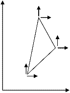
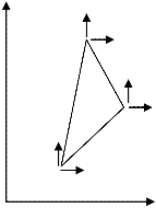
To assemble the global stiffness matrix K, consider the equilibrium of the one strut model in Figure 2.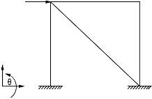
C D
11 L I L2 L
Symmetric 4
The structural or global stiffness matrix K is obtained by summing up the contribution from the 4 elements using standard structural mechanics technique.
H
The model was validated by comparing the deflection profile, obtained from the outputs of the one-strut model
Y' and those from the FE model based of the constant strain
A B plane triangular element. The basic concepts of the finite
X' element method are well documented [24-26]. Hence only
The relevant degrees of freedom (DOF)
d = dA , dB , dC, dD
The corresponding load vector
P = PA, PB, PC, PD
the essential features of the model will be presented here.
For this analysis, a three-node triangular finite element model with two degree of freedom (DOF) at each node is presented in Figure 3
IJSER © 2015 http://www.ijser.org
International Journal of Scientific & Engineering Research, Volume 6, Issue 3, March-2015 139
ISSN 2229-5518
y V y
U
3
V
2 U
1
the subroutines to take care of the overall analysis. The F F input data consists of specifying the geometry of the x idealized structure, its mechanical properties, the loading
3 and the support condition. The data also includes certain
control numbers that would help the efficiency of the
F program such as the total number of nodes and elements.
2 F
x 4.0 IMPLEMENTATION OF THE PROCEDURE
1
V U F F
x x
A typical representation of a single-bay single-storey
masonry infilled RC frame (Figure 4) under lateral static
x load is subjected to analysis using the FE model and the one
(a) (b)
The major assumptions of modeling masonry behavior under plane stress include
i the material is homogenous and elastic and hence obeys Hooke’s law
ii the displacement can be approximated by the polynomials
strut model and the opening in the infill panel varied from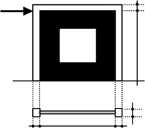
0% to 50% for structural models tagged IF01, IF02, IF03, IF04 and IF05. The triangularly mesh structure ready for finite element analysis is shown in Figure 5, while a typical one strut model is seen in Figure 6
u (x, y )
= α 1
+ α 2 x
+ α 3 y
(10)
v (D, y )
= α 4
+ α 5 x
+ α 6 y
With these assumptions, the element stiffness of the constant strain triangle has been established in the form
{k e } = { ∫ [B]T
[D] [B] d (vol )}
(11)
where B is the strain vector, D the elasticity matrix.
Substituting the volume of the triangular element, the
equilibrium equation for the analysis of a typical triangular element becomes
{F e } = [[B]T
[D] [B] ∆t ] {δ e }
(12)
Where ∆ represents area of triangular element and t
represents thickness.
The FE model used in this paper is supported by a visual
basic program developed by the authors. The computer program is divided into two parts. The first part consists of the routines for the control numbers and data input modules, the second part consists of routines for tabulated output of nodal displacements and element stresses. The basic steps to obtain the element stiffness matrix [Ke] and stress matrix [H] have already been discussed in details in the previous section and would involve voluminous numerical work, hence these processes were well built up in
IJSER © 2015 http://www.ijser.org
International Journal of Scientific & Engineering Research, Volume 6, Issue 3, March-2015 140
ISSN 2229-5518


![]()
C D P
Equivalent
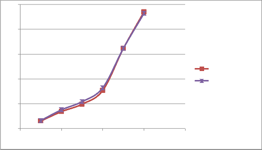
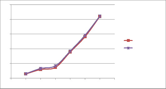
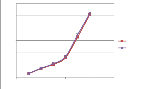
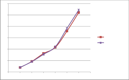
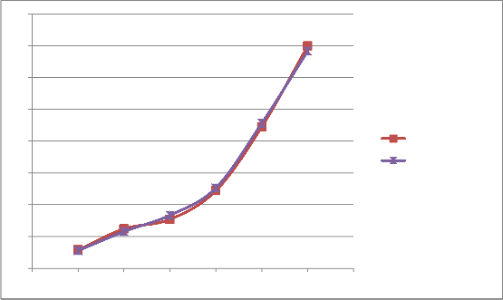
The computed results of the lateral displacement of the infilled frame, obtained on the basis of the one-strut and the finite element models for various values of applied horizontal loads and opening ratios are shown in Table 1 and plotted in Figure 7.
From the Table and plots, it can be seen that, the lateral displacement generally increased as the opening ratio increased, indicating the importance of the infill panel to the lateral resistance of the infilled RC frame structure.
The functional dependence of lateral deflection with load for a given opening ratio is represented by two linear segments with bifurcation occurring approximately at a lateral load magnitude of 200 kN, after which the graph suffers a steep accent. Meanwhile, the variation of lateral deflection with opening ratio for a given load is much gentle in the range 8 - 12.5 mm; 13 – 23 mm and 21 – 32.5 mm for load values of 200, 250 and 300 kN, respectively.
The results confirm that the average error between the two models is about 3.95%, while the highest and least deviations of 4.53% and 3.28% occurred on structural
diagonal Strut
A B
L = 3.30m
2.65m
models IF0 (10% opening) and IF05 (50% opening)
respectively. Hence, there is a close agreement between the outputs of the proposed modified one-strut model and the FE model underscoring the adequacy of the proposed model to reproduce the response of infill frames including those with openings.
IJSER © 2015 http://www.ijser.org
International Journal of Scientific & Engineering Research, Volume 6, Issue 3, March-2015 141
ISSN 2229-5518
Specimen | Opening Ratio % | Model | Deflection at different Load Application (mm) | |||||
Specimen | Opening Ratio % | Model | 50kN | 100kN | 150kN | 200kN | 250kN | 300kN |
IF01 | 10% | One Strut Model | 1.45 | 2.95 | 3.68 | 8.91 | 14.09 | 20.95 |
IF01 | 10% | FE model | 1.53 | 3.10 | 4.01 | 9.21 | 14.59 | 21.09 |
Diff. % | 5.52 | 5.08 | 8.96 | 3.37 | 3.55 | 0.67 | ||
IF02 | 20% | One Strut Model | 1.53 | 3.42 | 4.92 | 7.68 | 16.13 | 23.51 |
IF02 | 20% | FE model | 1.62 | 3.58 | 5.12 | 8.01 | 16.15 | 23.22 |
Diff. % | 5.88 | 4.68 | 4.06 | 4.30 | 0.12 | 1.23 | ||
IF03 | 30% | One Strut Model | 1.56 | 3.56 | 5.24 | 7.91 | 16.33 | 25.41 |
IF03 | 30% | FE model | 1.67 | 3.70 | 5.51 | 8.20 | 17.10 | 25.95 |
Diff. % | 7.05 | 3.93 | 5.15 | 3.67 | 4.71 | 2.12 | ||
IF04 | 40% | One Strut Model | 1.91 | 4.61 | 8.10 | 10.74 | 17.89 | 26.01 |
IF04 | 40% | FE model | 1.99 | 4.51 | 7.72 | 11.02 | 19.11 | 27.12 |
Diff. % | 4.19 | 2.17 | 4.69 | 2.61 | 6.81 | 4.27 | ||
IF05 | 50% | One Strut Model | 2.90 | 6.21 | 7.71 | 12.21 | 22.23 | 34.92 |
IF05 | 50% | FE model | 2.79 | 5.79 | 8.05 | 12.44 | 22.45 | 34.12 |
Diff. % | 3.79 | 6.76 | 4.41 | 1.88 | 0.54 | 2.29 |
25 Deflection (mm)
20
15
10
One-Strut Model
FE-Model
5
0
0 50 100 150 200 250 300 350
Load (KN)
25
Deflection (mm)
20
15
10
One-Strut Model
FE-Model
5
0 Load (KN)
0 100 200 300 400
International Journal of Scientific & Engineering Research, Volume 6, Issue 3, March-2015 142
ISSN 2229-5518
30
Deflection (mm)
25
20
15 One-Strut Model
FE-Model
10
5
0
0 100 200 300 400
Load (KN)
30
Deflection (mm)
25
20
15
One-Strut Model
FE-Model
10
5
0
0 50 100 150 200 250 300 350
Load (KN)
IJSER © 2015 http://www.ijser.org
International Jou 40
ISSN 2229-5518
35
DEFLECTION (mm)
143
30
25
20
15
One-Strut Model
FE-Model
10
5
0
0 50 100 150 200 250 300 350
Load (KN)
varies exponentially with the opening ratio and had the
In this paper, the possibility of modeling an infilled frame by modifying the pin-jointed single diagonal strut that replaces the brick infill is carried out. The ability of the
form λ m
= e0.06 β
.
modified diagonal area to appropriately model the effect of the varying opening sizes in the infill panel was established, resulting in close agreement of the model outputs with those from FE analysis.
The results confirm that the average error between the two
models is about 3.95%, while the highest and least deviations of 4.53% and 3.28% occurred on structural models IF0 (10% opening) and IF05 (50% opening) respectively. Hence, there is a close agreement between the outputs of the proposed modified one-strut model and the FE model underscoring the adequacy of the proposed model to reproduce the response of infill frames including those with openings.
From the results the following specific conclusions can be made
1. Opening naturally lead to reduction in the shear strength of the infill. The strength reduction factor due to opening
1. Naraine, K., andSinha, S.N. (1988), “Test of Brick Masonry Models Under Cyclic Compressive Loading”, Proc. 8th Int. Brick Masonry Conf., Dublin, Ireland, vol. 1, pp. 395-405.
2. The lateral displacement generally increased as the
opening ratio increased, indicating the importance of the infill panel to the lateral resistance of the infilled RC frame structure.
3. A unique value of lateral load of about 200kN, at which
the lateral deflection changes from gradual growth to rapid variation, was established for all opening ratios considered.
4. The variation of lateral deflection with opening ratio for a given load is much gentle in the range 8 - 12.5 mm; 13 –
23 mm and 21 – 32.5 mm for load values of 200, 250 and
300 kN, respectively.
The FE model used in this paper has already been validated in previous work by the authors [27]. However some important factors require further investigating. The consistency of the regression equation obtained for modification of the area of diagonal strut to different type of infill material is recommended to be considered. Furthermore a more generalized regression equation to account for different configuration and position of opening is recommended.
2. Naraine, K., andSinha, S.N. (1989), “Behavior of Brick Masonry under Cyclic Compressive Loading’, Journal of Strut. Engineering, ASCE, Vol. 115, No 6, pp. 1432-
1445.
3. Naraine, K., and Sinha, S.N. (1992), “Stress-Strain
Curves for Brick Masonry in Biaxial Compression”,
IJSER © 2015 http://www.ijser.org
International Journal of Scientific & Engineering Research, Volume 6, Issue 3, March-2015 144
ISSN 2229-5518
Journal of Structural Engineering, ASCE, vol. 118, No
6, pp. 1451-1461.
4. Asteris, P.G, andTzamtzis, A.D. (2002), “Non-linear
FE Analysis of Masonry Shear Walls”, Proceedings, International Masonry Conference, London.
5. Syrmakezis, C. A., and Asteris, P. G. (2001).
‘‘Masonry Failure Criterion under Biaxial Stress
State.’’ J. Mater. Civ. Eng., 13(1), 58–64.
6. Nwofor, T.C. (2011). Finite element stress analysis of brick-mortar masonry under compression. Journal of Applied Science and Technology vol. 16, Nos. 1&2, pp.33-37.
7. Holmes, M. (1961). ‘‘Steel Frames with Brickwork and Concrete Infilling.’’ Proc., Inst. Civ. Eng., Struct. Build., 19, 473–478.
8. Holmes M. (1963). "Combined Loading on Infilled Frames." Proceeding Of The Institution Of Civil Engineers, Volume 25: 31-38.
9. Stafford-Smith B.S. (1962). "Lateral Stiffness of Infilled Frames." Journal of Structural Division, ASCE, Volume 88, No. ST1: 183-199.
10. Stafford-Smith B.S. (1966). "Behavior of Square Infilled Frames." Journal of Structural Division, ASCE, Volume 92, No. ST1: 381-403.
11. Stafford-Smith B.S. (1968). "Model Test Results of
Vertical and Horizontal Loading of Infilled Frames." ACI Journal, Volume 65, No. 8: 618-625.
12. Thiruvengadam V. (1985). "On the Natural
Frequencies of Infilled Frames." Earthquake
Engineering and Structural Dynamics, Volume 13, No.
3: 401-419.
13. Chrysostomou, C.Z. (1991). "Effect of Degrading Infill
Walls on the Nonlinear Seismic Response of Two- Dimensional Steel Frames." PhD dissertation, Cornell University, Ithaca, N.Y.
14. Hamburger R.O. (1993). "Methodology for Seismic Capacity Evaluation of Steel-Frame Buildings with Infill Unreinforced Masonry." Proceedings of 1993
National Earthquake Conference, Central U.S. Earthquake Consortium, Memphis, Tennessee, Volume
2.
15. El-Dakhakhni, Wael W., Mohamed Elgaaly, and
Ahmad Hamid. (2003) "Three-Strut Model for Concrete Masonry-Infilled Steel Frames." Journal of Structural Engineering, Vol. 129, No. 2: 177-185.
16. Polyakov, S.V. (1960). On the interaction between masonry filler walls and enclosing frame when loading in the plane of the wall, Translation in earthquake engineering, Earth quake Engineering Research Institute, San Francisco, 36-42.
17. Smith B.S. and Carter C. (1969). A method of analysis
for infilled frames, Psoc.,lustn. Civ. Engrs. 44, 31 – 48
18. Mehrabi, A. B., Shing, P. B., Schuller, M. P. and
Noland, J. L. (1994). “Performance of Masonry-infilled R/C frames under In-plane Lateral Loads”, Report CU/SR-94/6, Struct. Engrg. And Struct. Mech. Research Series, Dept. of Civil, Environ. and Arch. Engrg., University of Colorado at Boulder.
19. Mohebkhah, A., A.A. Tasnimi, and H.A. Moghadam
2007. "A Modified Three-Strut (MTS) Model for
Masonry- Infilled Steel Frames with Openings." JSEE Vol. 9, No. 1 and 2 : 39-48.
20. Chrysostomou, C.Z., Gergely, P. and Abel, J. F.
(2002), “A Six-strut Model for Nonlinear Dynamic Analysis of Steel Infilled Frames,” International Journal of Structural Stability and Dynamics, Vol. 2, No. 3, 335- 353.
21. Hashemi, S.A. and Mosalam, K.M. (2007), “Seismic Evaluation of Reinforced Concrete Buildings Including Effects of Infill Masonry Walls,” Pacific Earthquake Engineering Research Center, PEER 2007/100.
22. Kadysiewski, S. and Mosalam, K.M. (2009), “Modeling of Unreinforced Masonry Infill Walls Considering In-Plane and Out-of-Plane Interaction,” Pacific Earthquake Engineering Research Center, PEER 2008/102.
23. Benjamin, J.E. and Williams, H.A. (1958). “The behaviour of one story brick shear walls”. J Struct. Div., ASCE, 84(4).
24. Samarasinghe, W. (1980). “The in-plane failure of brickwork,” PhD thesis, University of Edinburgh, Edinburgh, 285-292.
25. Lourenco, P.B., and Rots, J.G. (1997). “Multisurface interface model for analysis of masonry structures.” J. Eng. Mech., 123(7), 660-668.
26. Lourenco, P.B., and Rots, J.G., and Blaauwendraad, J. (1998). “Continuum model for masonry: Parameter estimation and Validation.” J. Struct. Eng., 124, 642-
652.
27. Nwofor, T. C., and Ephriam, M. E. (2014). “Validation of a FE micro model for RC frames.”International Journal of Innovative Research in Advanced Engineering, 1(9), 44 - 50.
IJSER © 2015 http://www.ijser.org