βp - βq =2π/˄
where ˄ is the spatial frequency of Micro bends. Light power will moves from the p-th to q-th mode.
International Journal of Scientific & Engineering Research, Volume 5, Issue 2, February-2014 827
ISSN 2229-5518
Prof.Dimple K. Baraliya
Abstract— Microbend due to pressure have been created in a 55µm graded index multimode optical fiber with spatial periodicity ˄=5.5mm enclosed in the araldite sample. W hen optical fiber having microbends applied high pressure, it may break and if optical fiber enclosed in solid structure without micro bend was applied high pressure then the sensitivity is lower. In this paper, an aggregation of micro bend sensor and high performance structure in the aerospace, of sensing high pressure on a structure with the sensitivity of a micro bend sensor without damaging the fiber. It gives pressure up to 1.8 Mpa with regeneration within ±5% measurable degree. The intermediate sensitivity of the fiber optic pressure sensor is 5.6 /Mpa on an arbitrary series.
Index Terms— fibre optic sensing, microbending, multimode step index, multimode graded index, optical fiber.
—————————— ——————————
1 INTRODUCTION
In 1870, British John Tyndall demonstrated that light can be guided through the curve of streams of water. As a result of total internal reflection light get confined to the streams of water and the streams looks lambent. A lambent water stream is the harbinger of an optical fiber. The transmission of images through optical fiber was realized in 1950’s.The laser technology used in 1960 motivated the researchers to study the optical fiber for data communication, sensing and other purposes. The appearance of optical fiber as commercial communication system was possible in 1977. Optical fibers have been ussed as fibro-scopes in medical diagnostics. Optical fibers sensor is used for detecting electrical, mechanical and thermal energies. Fiber optic sensors have been functioned for monitoring a wide range of environmental parameters such as position, strain, humidity, viscosity, chemicals, pressure, current, etc. The advantages of these sensors are that they are light weight, have remote sensing capability, have inability to conduct electric current and are cheaper. Fiber optic sensors can be classified as follows:
----Related to the process of modulation and demodulation, a sensor
too known as intensity (or amplitude), a frequency, a polarization, or a phase. As the variation of phase or frequency in optical fiber was observed later termed as interferometry sensor.
---- Related to their application: Physical application (e.g.measurement of stress, temperature, pressure); Chemical sensor (e.g. Endoscopes which shows measurement of blood flow, glucose content).The intensity type fiber optic sensor using Micro-bending as follows.
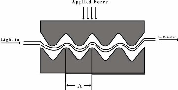
The optical fiber was bent to make cables; there is loss due to localized bending. The intensity of output light is proportional to the quantity of micro bending. The quantity of micro bending can be measured by finding the variation in output light intensity [7]. Due to micro bend fiber sensor, there is reduction in cost and when combined with optical time domain reflectometry techniques they must be used to cover a wide region. Micro bending was done by process of the spatial changes in the structure of an optical fiber. This stimulates couplings between the modes of optical fiber as shown in figure1 below. As a periodic micro bend is stimulate along the axis of fiber, light power is coupled between the modes of fiber with propagation constants βp and βq satisfying
βp - βq =2π/˄
where ˄ is the spatial frequency of Micro bends. Light power will moves from the p-th to q-th mode.
2. FIBER OPTIC
Optical fiber are made up of glass or plastic usually as thin as a human hair .Optical fiber refers to the medium and the technology associated with the transmission of information of light pulses along a glass or plastic fiber . Optical fiber carries more information than copper cables due to their higher bandwidth and need to retransmit Information of light pulses along a glass or plastic fiber .Many of the telephone companies long-distance lines are now generally made up of optical fibre.There are two types of fibers used in many propagation paths. A single mode fiber is used for longer signals. Many of the telephone companies long-distance lines are now generally made up of optical fibre.There are two types of fibers used in many propagation paths. A single mode fiber is used for longer distances communication (SMF) and multimode fiber is used for shorter distances communication (MMF). Single mode fiber can have either a step index or graded index profile. The advantage of graded index profile was to render dispersion modified single-mode fibres. SMF are designed such that it gives proper ITU-T recommendations, being fabricated from doped silica to generate high quality, wideband transmission fiber suited for telecommunication application. SMF have small core diameters to permit single mode propagation, the cladding diameter must be at
IJSER © 2014 http://www.ijser.org
International Journal of Scientific & Engineering Research, Volume 5, Issue 2, February-2014 828
ISSN 2229-5518
least 10 times the core diameter to avoid losses from the evanescent field. Therefore, SMF have same overall diameters as MMF due to coating and buffer jacket by giving protection and higher strength.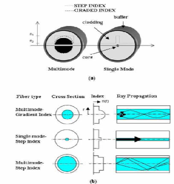
Multimode step index fiber may be prepared from multicomponent glass compounds or doped silica. Multimode step index fiber has large core diameters and large numerical aperture alleviate efficient coupling to incoherent light source e.g. LEDs. These fibers have limited bandwidth and low cost prices. Multimode graded index fiber may be prepared by using multicomponent glasses or doped silica. Multimode graded index fiber leaned to fabricated from material with higher purity as compared Multimode step index fiber in loss. Hence, from above it is clear that Multimode graded index fiber have better performance than Multimode step index fiber due to the index grading and lower attenuation. Multimode graded index fiber leaned to smaller core diameter than Multimode step index fiber as shown in fig 2 below. Figure2 shows the different types of fibers.
3. FIBER OPTIC SENSORS
Optical fiber sensor augmented composite polymer to bring about radical change in the design of large high performance structure in the aerospace, marine and power generation companies due to their greater response to resisting corrosion because of their higher strength. Optical fiber sensor has gained more importance in recent year as a straight way for lifetime inspections and diagnosis due to the fact the sensor do not require a power supply and are capable to be measured over a long distance.Fibre optic sensor shows high senility and greater accuracy in the measurements of strain,
temperature in several structures. Optical fiber sensors for temperature and pressure have been developed for down-hole measurements in oil wells. It is also used as optical gyroscopes in the designing of Boeing 767 and in Hydrogen microsensors.They are
used as light guides in medical application where bright light necessary to be brought is to focus on a target except clear line of-sight path. Optical fiber illumination is also used for decorative applications, including signs, arts and artificial Christmas trees. Swarovski boutiques use optical fibers to illuminate their crystal showcases from many different angles while only employing one light source. Optical fiber is an intrinsic part of the light transmitting concrete building product, LiTracon. Optical fiber can be considered in miniaturizing optical sensor. Because of their light weight, optical fibers are special employed in aeronautics and crucially in space application. The optical fiber sensor has immunity to when make them very suitable for accurate measurements. Because their lightweight, small size, high sensitivity, large bandwidth they are popular as multiplexed or distributed sensors. And are recommend- ed for wider studied measurable such as pressure, temperature and strain. In some cases, metals could be used for packaging when metal does not present a problem, but an all-glass and polymer sensor has great advantages when interferences with an electromagnetic field is synchronized. The materials used in the construction and packaging of sensor are biocompatible and chemically inert, which makes optical sensors worthy for physical, chemical or biomedical as shown in figure 3.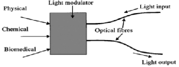
4. Experimental details
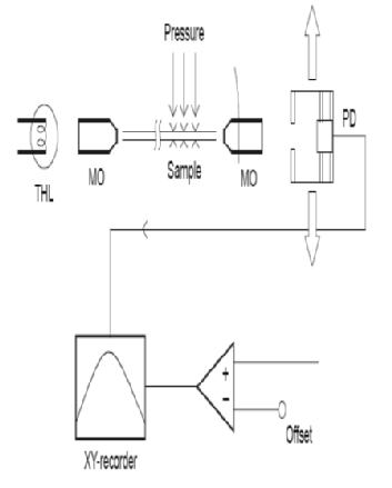
Sample of araldite with 40% hardener and 15% aniline was mixed with 55µm graded index multimode optical fiber embedded in it [5], [6], [7] and [8]. There is creation of ramp structures with spatial periodicity ˄=5.5mm during the process of preparation, with the fiber inside the samples touching the ramps. A tungsten halogen lamp through 10X microscope objective was placed and the light was made incident in the 55 µm parabolic index optical fiber by means of an incoherent source of light. A magnifying image of the fiber output was made to fall onto the plane of an aperture photo detector handled by a stepper motor so as to scan the image along its diameter. The output was given to the detector which is connected to XY-recorder which gave near field intensitydistribution. The experiment performed is as shown below in fig 4.
IJSER © 2014 http://www.ijser.org
International Journal of Scientific & Engineering Research, Volume 5, Issue 2, February-2014 829
ISSN 2229-5518
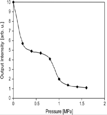
The pressure was applied to the sample by means of a hydraulic pressing machine and the output intensity was observed as the measured value of pressure. The above experiment has been performed under laboratory condition and the temperature has been kept constants at 270C within ±0.50C variation. It was observed that there was no change in temperature and therefore the modulation in the output signal is completely dependent upon the change in pressure of the sample. The figure 5 below shows that the curve of output intensity verses pressure increasing at the output. It is observed that as the pressure is increased, there was more and more coupling happened in cladding modes and core modes. The figure given below shows a regular change in value of output intensity with
increasing pressure. Hence from above explanation we can define sensitivity as the curve between output intensity and pressure.
When the light is incident in the optical fiber, it is shared by both the core and the cladding. As the pressure is increased, the cladding takes place between the cladding modes and higher order core modes. The effect of pressure is more concentrated into the plastic jacket and the cladding in an optical fiber. The decrease in output intensity with increase in pressure proves that the intensity modulated fiber optics pressure sensor can be used to monitor the pressure up to 1.55Mpa under high pressure cyclic operation.
5. Result
The structure is monitored by consolidating in-situ of the fiber at the time of making the structure itself. There is continuous decrease in the output intensity of light with increase in pressure in the embedded structure explained here can be victimized to monitor unceasingly the pressure up to 1.55Mpa under high pressure cyclic operation. It can be exploited to find out maximum pressure that the structure can withstand. The breaking of optical fiber due to an increase in pressure to dangerous levels make it shows of higher pressure in the structure. In case of araldite sample, light glows where it has occurred and upon breakage the output suddenly decreased. As the structure of sample is semi-transparent, a precise spot of breakage in the fiber can be pointed out. The results found here shows regeneration of structure. This sensor is full-bodied, cost effective and authentic for measuring excess pressure. It can be exploited to find out defects in the structure and for finding out more loads that structure can withstand properly [3], [4], [5], [6], [7] and [8].
6. Conclusions Fiber optic sensor is very flexible and adjustable and it can be set
IJSER © 2014 http://www.ijser.org
International Journal of Scientific & Engineering Research, Volume 5, Issue 2, February-2014 830
ISSN 2229-5518
at any desired level. It can be concluded that the fiber optic sensors can be successfully used for accuracy of structures and measurement of various physical parameters. New ideas are being continuously developed and tested not only for the traditional measured but also for new application. Figure 5 shows pressure versus output intensity on an arbitrary scale for one such intermediate cycle after 78 hours. Here, we again noticed that initially a large decrease in the intensity, then a gradually decreasing trend. Hence, Sensitivity in the present scheme of things has been defined as the slope of the curve between the output intensity and the pressure. The slope has been calculated for various ranges of pressure and then the average has been taken to calculate the mean sensitivity. The power plunged in the optical fiber was shared by both the core and cladding. As the pressure is increased, the coupling proceeds between the cladding modes and higher order core modes. Therefore, there is small incursion into the cladding region as the lower order modes are more saturated into the core region. The pressure was greatly affected the plastic jacket and the cladding in an optical fiber. There is small contortion of the silica core. Thus, when the pressure was increased, the nature of the fundamental and other lower order modes changed slightly.
7. References
[1] HALE K.F, Optical fiber sensors for inspecting monitoring, Physics in Technology 15, 1984, pp. 129–35.
[2] UDDE., Embedded sensor make structures smart, Laser Focus
Embedded 24, 1988, p.135.
[3] LAGAKOS N., COLE J.H., BUCARO J.A., Microbends fiber
Optic sensor, Applied Optics 26(11), 1987, pp. 2171–80.
[4] LEE D.C., LEE J.J., KWON I.B., SEO D.C., Monitoring of fatigue damage of composite structures by using embedded intensity based optical fiber, Smart Materials and Structures
[5] Cumshaw, B., and Dakin, J., Optical Fiber Sensors: Systems and
Applications, Artech House, Boston, 1989.
[6] R.Willsch and R. T. Kerstin, Eds., Fiber Optic Sensor. Ser. SPIE Milestone. Bellingham, WA: SPIE, 1995, vol. MS108.
[7] FIBER OPTIC SENSORS AND THEIR APPLICATIONS Fidanboylu, Kea, *, and Efendioglu, H. S.b
A, * Faith University, Istanbul, Turkey, E-mail: kfidan@fatih.edu.tr
B Faith University, Istanbul, Turkey, e-mail:
hseckin@fatih.edu.tr
[8] Fiber optic pressure sensor and monitoring of structural Defects N.K. PANDEY*, B.C.YADAV.Materials and Sensors Research Laboratory, Department of Physics, Lucknow University, Lucknow-226007, U.P., and India*Corresponding author:
N.K.Pandey, nkp1371965@rediffmail.com, nkp1371965@yahoo.co.in
• Prof.Dimple Baraliya is currently working as an Assist.Prof in Mau li Group of Institutions, College of Engineering and Technology, Shegaon
Email: dkbaraliya@gmail.com
IJSER © 2014 http://www.ijser.org