International Journal of Scientific & Engineering Research, Volume 3, Issue 8, August 2012 1
ISSN 2229-5518
Designing and Conducting Experiments for Optimization of satisfactory Cutting conditions in Micro Turning by using Titanium Alloy
S.Selvakumar, R.Ravikumar, K.Raja
Abstract: Micromachining is the basic technology for the production of miniaturized parts and components, which plays an important role in today’s manufacturing technology. Miniaturization of industrial products had been the trend of technological development. Mic ro-component fabrication requires reliable and repeatable methods with accurate t ools. Many common methods of manufacturing miniature components have been established in semi-conductor processing techniques, usually in large batch production. Therefore in this work, an attempt is made to machine Titanium Alloy by micro turning using mechanical micro machine tool. Micro turning is similar to that of conventional turning process but operating at the micron scale of parameters to produce micro components. In this work the cylindrical work piece of Titanium Alloy is planned to micro turned with the cutting speed of (51, 61 and71 m/min), depth of cut (1, 2 and 3µm) and feed (5, 10 and 15 µm/rev) using the Cermet tool. Full factorial experiments were performed by using a programmable multi -purpose micro machine tool (make Mikrotools DT110). For every set of experiments the output parameters such as the Tool wear and the Surface roughness were measured by using the video measuring system and the Surface roughness tester. Signal to Noise ratio and Analysis of variance are to be e mployed to investigate the performance characteristics in turning of Titanium Alloy using Cermet tool.
Keywords: ANOVA, Full factorial Experiment, Micro turning, Surface Roughness, Signal to Noise Ratio, Tool wear.
—————————— ——————————
1 INTRODUCTION
Ptimization of machining conditions in Microturning of Titanium Alloy is the aim of this project. At the present stage, I carried out the following.

Code generation in microturning.
Experimental set-up and Determination of

machining performance. Experimental procedure. Experimental Design.
Among the twenty seven, nine experiments were done at various levels of micro-turning parameters.
In future, the remaining 18 experiments are to be carried out and based on that result, the cutting parameters were to be optimized.
Z.Lu, T.Yoneyama,1 et al (1999), revealed that, if the applications of these conventional machining methods become available for the micro manufacturing process, the production process for micro parts will be advanced as an extension of the traditional material process. Therefore, the control of the reacting force during cutting is one of the important factors in improvement of machining accuracy. The value of the cutting force must be low and that causes plastic deformation of work piece.
————————————————
 S.Selvakumar, Assistant Professor in Mechanical Department, Roever Engineering College, Perambalur-621212. India. Mobile:+91 9443864878. E.Mail:sdy.12@rediffmail.com
 R.Ravikumar, Professor in Mechanical Department,
PGP College of Engineering & Texhnology, Nammakkal-637207. India. Mobile:+91 99865097799.E.Mail: ravikumar_mech@yahoo.com
 K.Raja, Assistant Professor in Mechanical Department,
Sri Jayaram College of Engg. & Technology, Cudalore, India.
T.Masuzawa, et al 2 (2000),Microturning has the capacity to produce 3D structures anMicro scale. As solid cutting tool is used in Microturning and it can produces definite 3D shapes. In order to accurately and precisely control of cutting tool motions during machining, cutting path generation by CNC programming is employed. The major drawback of micro turning process is that the machining force influences machining accuracy and the limit of machinable size. Nabhani, F.,3 (2001), For example, Titanium alloy components make up 20-30% of the dry weight in a jet engine. However, because of their high strength and low thermal conductivity. M.Azizur Rahman4 ., (2005) If the cutting tool performance in Microturning was investigated while machining of brass PCD and cermets inserts. During this machining, abrasive wear of cermet insert was observed on the flank face while PCD insert showed groove wear in the flank face. D.I.Lalwani et al 5 (2008), the Cutting speed has no significant effect on cutting forces and surface roughness. The feed rate provides primary contribution and influences most significantly on the surface roughness. The interaction between the feed rate and the depth of cut, quadratic effect of feed rate and interaction effect of speed and depth of cut provides secondary contribution to the model. Q.Wu N.Fang6(2009) were derived one experimental analysis under the same cutting conditions, the cutting force and the thrust force in machining Inconel 718 was higher than those in machining Ti-6Al-4V. From this analysis, as the feed rate increases, the cutting, thrust, result forces and force ratio all increases. Ulvi Sekar et al7 (2004), The Surface roughness values were found to be decreased with the increasing
IJSER © 2012
http://www.ijser.org
International Journal of Scientific & Engineering Research, Volume 3, Issue 8, August 2012 2
ISSN 2229-5518
cutting speed. This can be attributed to the presence of built- up-edge at the lower cutting speed. In homogeneous
distribution of chip thickness at the lower cutting speed may also indicates the variation in the cutting forces and this may be another reason for poor surface finish due to the force fluctuations.
2 IMPORTANCE OF MINIATURE COMPONENTS
Miniaturization components play an important role in various applications, such as aerospace, automotive, electronics, biomedical, communications, and environmental. Miniature components provide low power consumption and high heat transfer, since their surface –to-volume ratio is very high. However miniature components fabrication requires reliable and repeatable methods with accurate tools. The common method of manufacturing miniature components is by micromachining, which is mostly used for semi-conductor processing for a large batch production. The majority of these methods are slow and limited to a few silicon-based materials.
The miniature components are used in the following applications:
 In biotechnology and medicine, where micro size machines would be needed to work inside the cells and tissues.
 In harsh environments, such as in vacuum, under pressure and ionizing radiation where traditional machines could not be operated.
 In narrow spaces or narrow channels where
conventional machines cannot reach.
 Micro actuators and micro fittings could be used to assemble the small instruments and soft machines.
3 MICROTURNING
Microturning is a conventional material removal process that has been miniaturized. Microturning has the capacity to produce 3D structure on micro scale.
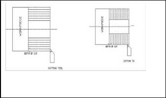
Fig. 3.1Turning by parallel cut Fig. 3.2 Turning by to work piece axis step cutting
As solid cutting tool is used in microturning can produce the definite 3D shapes. In order to accurately and precisely
control the cutting tool motions during machining, cutting path generation by computer programming is employed.
For carrying out the process of microturning, the workpiece and the cutting tool must be moved relatively to each other in order to separate the excess layer of material in the form of chips. Hence the motion of the cutting tool with respect to the workpiece is important. In this respect, the cutting path generation has been given emphasis. A microshaft with a high aspect ratio and micron range diameter cannot be machined by a cut, parallel to the axis of the job as in conventional machining as shown in Fig.3.1. As the machining on the shaft tends to deflect because the diameter reduces and the unsupported length of the workpiece increases. The Fig. 3.2 describes one possible way of the fabrication of miniature shafts by the step cutting process. Unlike the conventional parallel cut turning, in this work, turning is carried out in a step wise manner, which will help in minimizing the deflection of the shaft. The major drawback of micro turning process is that the machining force influences machining accuracy and the limit of machinable size. Therefore the control of the reacting force during cutting is one of the important factors in improvement of machining accuracy. To overcome the workpiece deflection in microturning, the value of the cutting force must be low and it causes the plastic deformation of the workpiece.
3.1 APPLICATIONS OF MICROTURNING
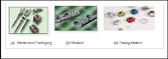
The need for microturned component possessing three- dimensional micro/mesoscale features and sub-micron surface finish keeps increasing rapidly in the fields of optics, semiconductor, biomedical devices and precision molds etc. Specific applications include micro scale pumps, valves and mixing devices, micro-fluidic systems, micro-molds, micro- holes for fiber optics and micronozzels for high-temperature jets. These applications require very close tolerances and high quality surface finish. The functional and structural requirements of these devices demand the use of various engineering materials including aluminium alloys, stainless steel, titanium, brass, plastics, ceramics and composites. The typical samples of micro-turned parts are shown in fig.3.3. The Fig.3.3 (a) shows the typical micro electronics packaging elements and Fig.3.3 (b) shows a high aspect ratio Medical application parts with diameter of 0.1mm and length of
15mm. This high aspect ratio could be achieved by using the microturning with minimized step size of less than 0.5 mm. The Fig.3.3 (c) shows microgears with different diameter and feature. The shafts are being used as main shaft for the ultrasonic micro motors.
IJSER © 2012
http://www.ijser.org
International Journal of Scientific & Engineering Research, Volume 3, Issue 8, August 2012 3
ISSN 2229-5518
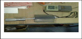
5.1 Machine Tool
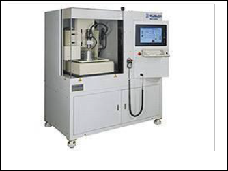
Fig. 3.3 Microturned Parts
Fig.3.4 shows a compound micropin produced by a micro- turning which is used for the micro surgical operations.
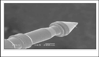
Fig.5.1 Machine Tool
Fig.3.4 SEM image of compound shaped micro pin
The present analysis is concentrated on microturning of cylindrical parts of commercially available Titanium Alloy with Cermet cutting tools in a micromachining machine tool setup.
4 MOTIVATION AND PROBLEM STATEMENT
5.1.1 Machine Specifications
Make: Micro tools DT 110, Singapore. Model: Multipurpose Micro machine.
1. Travel
i. X-axis: 200mm ii. Y-axis: 100mm iii. Z-axis: 100mm
2. Table Working Surface: 350 × 200 mm
3. Spindle Head: AC Servo; 100W
(1-5000rpm)
4. Machine Accuracy: ± 1 Micron
5. Resolution: 0.00025 mm
6. Table: Granite Base;
The major limitation of microturning process is that the machining force influences the machining accuracy and the
5.2 Material selection
600 × 600 × 130 mm
limit of the machinable size. Therefore, the control of the
reacting force during cutting is one of the important factors in improvement of machining accuracy. The value of the cutting force must be low and it causes the plastic deformation of the workpiece. This is an effective method of overcoming workpiece deflection in microturning process. With the availability of Micro machining centre (Micro tools DT 110, Singapore Make), no cutting data regarding selection of cutting parameters is available. Hence it has been decided to carry out the detailed experimental analysis is required to arrive the proper machining condition for the standard work pieces. The effects of the depth of cut, feed rate, and spindle speed were to be considered for this analysis.
5 EXPERIMENTAL DETAILS
The detail of the equipments used for performing the micro turning is given in the following section.
From the literature survey it has been observed that there is no attempt is made to machine Titanium Alloy in microturning, however it is required for many applications. Therefore in this work an attempt is made to perform microturning of Titanium Alloy. Titanium is the 22nd element on the periodic table. Its atomic weight is 47.867amu. It is a low density element (4510kg/m3); approximately less dense than that of steel. It is nonmagnetic, and transfers heat well. Its melting point (1993K [3020 degrees F and 1650 degrees C]) is also higher than that of steel. Its usability lies in its many benefits. Titanium Alloy may be heat treated to increase its strength. It can be used in welded construction at service temperature of up to 600º F. This alloy offers its high strength at a light weight, useful formability and high corrosion resistance.
Titanium Alloy is heat treatable, high strength, low weight material. The most commercially available Titanium Alloy is known as the ‚workhorse‛ of the titanium alloys, Titanium
IJSER © 2012
http://www.ijser.org
International Journal of Scientific & Engineering Research, Volume 3, Issue 8, August 2012 4
ISSN 2229-5518
Alloy, or Grade 2 Titanium, is the most commonly used of all the titanium alloys. It accounts for 50 percent of total
titanium usage the world over.
Titanium Alloy usability makes it the best alloy for the usage
in several industries, like the aerospace, medical, marine and chemical processing industries. It can be used in the creation of such technical things as:

Aircraft turbines
Engine components
Aircraft structural components
Aerospace fasteners
High-performance automatic parts
Marine applications
Sports equipments
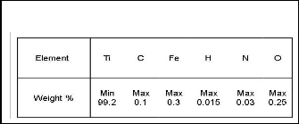
The composition and their level of Titanium Alloy is given below:
Table 5.1 Chemical composition (%) of Titanium Alloy
Gr.2
5.3 Cutting Tool for Micro turning
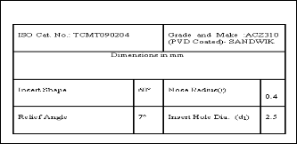
The turning operation involves cutting using a Cermet single point cutting tool (Fig.5.2) to machine Titanium Alloy. The cutting tool details are listed in Table 5.2. Sumitomo type STGCR 1010-09 mini tool holder was used for holding the tool shank.
Table 5.2 Cutting Tool Specification
5.4 Microturning Parameters
Similar to the conventional turning process, the factors influencing microturning of a work material are tool material, tool geometry, tool coating, coolant, vibration, cutting speed, feed, and depth of cut. Among these factors, the parameters which are planned to vary in this work are

Cutting Speed (m/min)
Feed (µm / rev)
Depth of cut (µm)

Microturning involves less feed and depth of cut usually in the range of few microns whereas in normal turning operation these parameters are in the few millimeters range.
Fig. 5.2 Cermet Tool
5.4.1 Cutting Speed
Speed refers to the spindle and the workpiece rotating speed, where it is stated in revolution per minute (rpm) or the surface speed, the speed at which the work piece material is moving past the cutting tool. Surface speed is the product of the rotating speed and the circumference of the workpiece before the cut is started. It is expressed in surface meter per minute (m/min) and it refers only to the work piece. The formula for speed in m/min from rpm is given in Equation-1.
V = (Л ×D×N) / 1000 Eqn. (1) Where V – Cutting Speed in m/min
D – Workpiece diameter in mm
N – Spindle Speed in rpm
Every different diameter on a work piece will have a different cutting speed, even though the rotating speed remains the same. The spindle speed range available in the DT 110 machine tools is 0-5000 rpm with safe operating limit restricted to 4000 rpm in the upper limit.
5.4.2 Feed
Feed refers to the cutting tool, and it is the rate at which the
tool advances along its cutting path. The feed rate is directly related to the spindle speed and is expressed in microns per revolution (of the spindle). The machine tool has a minimum feed rate of 1 mm/min.
F = f×N×1000 Eqn. (2) Where F – Feed in mm / min
f – Feed in µm / rev
N – Spindle Speed in rpm
IJSER © 2012
http://www.ijser.org
International Journal of Scientific & Engineering Research, Volume 3, Issue 8, August 2012 5
ISSN 2229-5518
5.4.3 Depth of Cut
The Depth of Cut is the thickness of the layer being removed
from the work piece or the distance from the uncut surface of the work to the cut surface and it is expressed in microns (µm).
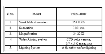
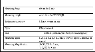
Table 5.3 Specification of Video Measuring system
t = ((d1 - d2) / 2) Eqn. (3)
Where t = Depth of cut in µm
d1 – Diameter of uncut surface in mm
d2 – Diameter of cut surface in mm
5.5 Code Generation in Microturning
Borland C++ Builder 6.0 is used for generation of the NC
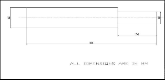
codes. The typical turned component is shown in Fig. 5.3.
One sample program is explained below
0 , 6.5, - 15.0 , 6.5, 0 , 0
1 , 4.5, -15.0 , 4.5 , -10.0 , 0
2 , 1, -10.0 , 1, -5.0, 0
3, 0.5, -5.0, 0.5, 0.0, 0
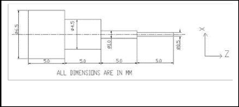
Fig. 5.4 Video Measuring System
Fig.5.3 Typical turned component
The first digit in each row indicates the block numbers. In ‘0’ block, the initial diameter of the bar and the machining length is specified. In ‘1’ block, the largest diameter of bar to be machined and its machining length is specified. In ‘2’ block, the next largest diameter and the machining length of that diameter is specified. Like these blocks are specified and these files are saved in ‘.txt’ format. The next step is importing this file to ‘SLICER’.
5.6 Determination of Machining Performance
To determine the machining performance, the output parameters such as tool wear and surface roughness of the work piece were measured.
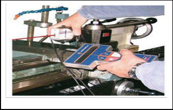
5.6.1 Tool Wear Measurement
The tool wear on the flank side of the tools was measured using a non contact video measuring system (Fig.5.4) at interval of 10 minutes after machining. The specification of the video measuring system is shown in Table 5.3.
5.6.2 Surface Finish Measurement
The surface roughness parameters such as Ra, Rz and Rt
were measured by using stylus based surface roughness tester (Surfcorder SE3500) is shown in Fig.5.5.
1. Ra: Arithmetic average of the absolute values of
the roughness profile ordinates, also known as Arithmetic Average (AA), Center Line Average (CLA). The average roughness is the area between the roughness profile and its mean line, or the integral of the absolute value of the roughness profile height over the evaluation length.
Fig. 5.5 Surface Roughness Tester
2. Rz: Arithmetic mean value of the single roughness depths of consecutive sampling lengths. Z is the sum of the height of the highest peaks and the lowest valley depth within a sampling length.
3. Rt: Maximum height of the profile.
IJSER © 2012
http://www.ijser.org
International Journal of Scientific & Engineering Research, Volume 3, Issue 8, August 2012 6
ISSN 2229-5518
Roughness measuring conditions are

Cutoff length0.25 mm
Evaluation length0.50 mm Sampling length0.80 mm Measuring speed0.05 mm/s Vertical magnification1000
Horizontal magnification2000
Table 5.6 Full factorial Experiment
Table 5.4 Specification of Surface Tester
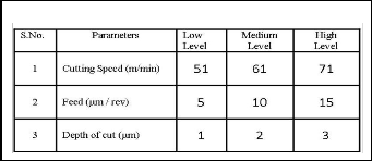
5.7 Experimental Design
The experimental design involves the selection of suitable levels for the machining parameters i.e. speed, feed and the depth of cut. Based on the machine tool, cutting tool and work piece capacity selection of the parameters were made as listed in Table 5.5. The parameters each at three levels result in 27 combinations and full factorial experiments were conducted (Table 5.6).
Table 5.5 Parameters and their Levels
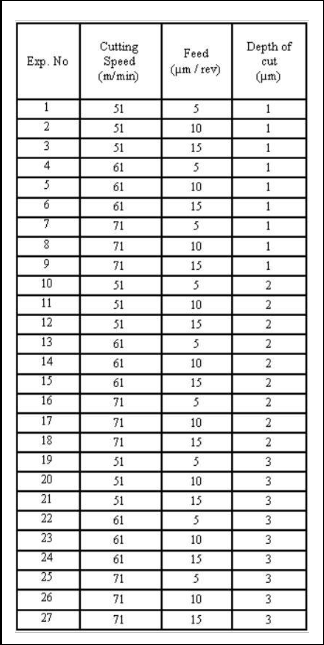
5.8 Experimental Procedure
The flank wear was considered as the direct indicator of tool status. Fresh Cermet was used to turn the Titanium Alloy rods under different cutting conditions (Table 5.6). At each cutting condition, the wear of the tool at every 10 minutes interval and the surface finish of the components were measured. No coolant was used during micro turning process.
IJSER © 2012
http://www.ijser.org
International Journal of Scientific & Engineering Research, Volume 3, Issue 8, August 2012 7
ISSN 2229-5518
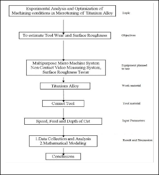
The methodology adopted for this project is illustrated in
Fig.5. 6.
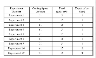
Table 5.7 Experiments conducted at various levels
5.10 Result of the above Experiments
The following Table 5.8 shows the measured values of a particular experimental level by using the video measuring system and the Table 5.9 shows the output measured surface roughness responses by using the surface tester.
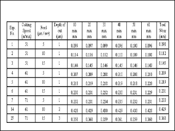
5.10.1 Tool Wear Measurement
Table 5.8 Tool Wear Measure for every
10th min. Interval
Fig.5.6 Methodology of the proposed Work
5.9 Experiments Conducted at various Levels of
Microturning Parameters
The following Fig, 5.7 shows the turned piece of a particular material and the Table 5.7 shows the proposed experimental level by using the cermet insert.
Fig. 5.7 Turned Component
IJSER © 2012
http://www.ijser.org
International Journal of Scientific & Engineering Research, Volume 3, Issue 8, August 2012 8
ISSN 2229-5518
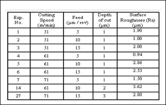
5.10.2 Surface Roughness Measurement
Table 5.9 Measured Surface Roughness (Ra)
6 CONCLUSION
6.1 Work done
1. Extensive literature survey has been carried out in the following areas such as

Micromachining.
Microturning of various combination of workpiece material and tool.
2. Selection and procurement of materials

Titanium Alloy is selected as workpiece material.
Cermet is selected as tool material.
3. Design of Experiments
 Microturned parameters such as Cutting speed, feed
rate and depth of cut and their levels are selected.
 Trail run have been carried out to familiarize in the
microturning process. Based on the experimental
design nine experiments were conducted.
6.2 Work to Be Done
 The remaining experiments (18Nos.) have to be conducted as per the full factorial method.
 During each experiment the Tool wear and the Surface roughness of work piece has to be measured by using Video measuring system and Surface Roughness tester respectively.
 Regression analysis has to be carried out to predict
the Tool Wear and the Surface Roughness.
 Taguchi analysis has to be carried out to find out the
optimum parameters to get the lower tool wear and better Surface roughness.
REFERENCES
[1] Z.Lu, T.Yoneyama, (1999),’ Micro cutting in the Lathe Turning System’ International Journal of Machine Tools and Manufacture, Volume 39, Pages 1171-1183.
[2] T.Masuzawa, (2000),‘State of the art of Micromachining’
Annals of the CIRP’ Volume 49(2), PP 473-488.
[3] Nabhani, F., (2001) ‘Machining of aerospace Titanium Alloys’ Robotic Computer Integrated Manufacturing’ Volume 17, PP 99-106.
[4] M.Azizur Rahman , M.Rahman , A.Senthilkumar,
H.S.Lin (2005),’CNC Micro turning an application to
miniaturization, International Journal of Machine Tools
& Manufacture, Volume 45, PP 631-639.
[5] D.I.Lalwani, N.K.Mehta, P.K.Jain, (2008) ‘Experimental Investigation of cutting parameters influence on cutting forces and surface roughness in finish hard turning of MDN 250 steel’ Journal of Materials Processing Technology, Volume 206, PP 167-179.
[6] N.Fang, Q.Wu (2009), ‘A Comparative study of the cutting forces in high speed machining of Ti-6Al-4V and Inconel 718 with a round cutting edge tool, Journal of Materials Processing Technology, Volume 209, PP:4385-
4389.
[7] Ihsan Korkut, Mustafa Kasap, Ibrahim Ciftic, Ulvi Seker (2004), ‘Determination of Optimum cutting parameters during machining of AISI 304 austenitic stainless steel’ Materials and Design, Volume 25, PP:303-305.
[8] K.S.Woon, M.Rahman, K.S.Neo and K.Liu, (1994), ‚ The
effect of tool edge radius on the contact phenomenon of tool-based micromachining‛ Journal of Precision Engineering, Volume 16, Pages 70-71.
[9] W.H.Yang and Y.S.Tang, (1998), ‚Design optimization of cutting parameters for turning operations based on the Taguchi method‛, Journal of Materials Processing Technology, Volume 84, Pages 122-129.
[10] Zafer Tekiner and Sezgin Yes ilyurt (2004),
‚Investigation of the cutting parameters depending on process sound during turning of AISI 304 austenitic stainless steel‛ Journal of Materials & Design‛ Volume
25, Pages507-513.
[11] Isan Korkul, Mustafa Kasap, Ibrahim Ciftci and Ulvi
Sekar, (2004), ‚Determination of optimum cutting parameters during machining of AISI 304 austenitic stainless steel,‛ Journals of Materials and Design, Volume 25, Pages 303-305.
[12] Kai Liu and Shreyes N.Melkote (2006), ‘Effect of plastic
side flow on surface roughness in micro-turning process’, International Journal of machine tools and manufacture, Volume 46 ,Pages 1778-1785.
[13] Gowri.S.; Kumar, P.Ranjith;Vijayaraj, R.; Balan, A.S.S.,
(2007), ‘Micromachining technology for the future’,
IJSER © 2012
http://www.ijser.org
International Journal of Scientific & Engineering Research, Volume 3, Issue 8, August 2012 9
ISSN 2229-5518
International Journal of Material and Structural Integrity, Volume 1, Pages 161-179.
[14] Hasan Gokkaya and Muammer Nalbant, (2007), ‘The effects of cutting tool geometry and processing parameters on the surface roughness of AISI 1030 steel’, Journals of Materials and Design’ Volume 28, Pages 717-
721.
[15] Leonardo R.Silva.J.Paulo Davim. Antonio Festas.
A.M.Abrao, (2009) ‘Machinability aspects concerning
micro-turning of PA66-GF30-reinforced polymide’, International Journal of Advanced Manufacturing Technology, Volume 41, Pages 839-845.
[16] P.Ranjith Kumar, A.S.S. Balan, S. Gowri, (2010),
‘Monitoring and prediction of tool wear in microturning
of copper, International Journal of Precision Technology, Volume 1, Pages 343-355.
IJSER © 2012
http://www.ijser.org