International Journal of Scientific & Engineering Research, Volume 3, Issue 4, April-2012 1
ISSN 2229-5518
Designing an Automated Wheel chair with Stair
Crossing Facility
Mst. Nasima Bagum, Choudhury Abul Anam Rashed, Sanjoy Kar
Abstract—now a day‟s all comforts in human life is the result of revolutionary advancement in technology. Modern Automation techniques; a part of technology is utilized in this design of “Automated Wheelchair” to give user a fully automated control. But the key story is not about control. The key approach was to find an easier way to cross inclined stairs with users. A new phenomenon was found from engineering analysis to cross stairs in an efficient way by the proper selection of wheel radius. The comfort is dedicated to the people who are suffering in normal movement. The developed „Automatic Wheel Chair‟ would provide a comfortable and dynamic life-style to the handicaps which might be very much closer to their dreams.
Index Terms—Automation, Ergonomics, Handicaps, Power, Stairs, Wheel Chair, Wheel radius.
—————————— ——————————
1 INTRODUCTION
A special type of wheel chair is designed which can be used to ride on stairs. So many works were done on automated wheelchair. But this factor was not considered or solved before in the way which would be discussed later. Emphasis was giv- en on solving the problem as well as other facilities provided before. Giving ease to user in different postures is another im- portant purpose [1]. The design presented in this paper will provide more physical and psychological advantages to the user because of scientific approaches and creativities. Our de- sign will provide complete automatic control and higher me- chanical efficiency. The most important thing is that, we in- cluded new scientific criteria (found by our analysis and expe- riment) that would provide the facility to ride on stairs that was not provided before. Obstacles in free movement are a curse to a human life. The wheel chairs available in the market provide them little facilities but it needs a lot of manual work done by users or helper to be operated. Its’ movement area is limited also. This limitation creates a mental stress on a handi- cap specially those who are handicaps by accident [2]. These phenomena added fuel to fire in this thinking and this is why a highly efficient wheel chair is presented.
2 STATE OF THE ART
Dugas [3], invented the "Safer Automatic Wheelchair Wheel Locks". As the medical director of the Marion Nursing Home for some three decades, he became aware of the problem of wheelchair-related falls among semi-ambulatory patients who did not or could not remember to use manual brakes on their wheelchairs. Some patients in wheelchairs, particularly the elderly, have a tendency to fall and injure themselves whentry- ing to stand because they fail to engage the manual locks. Du- gas [3] hence attempted to find a way to save these patients from potentially debilitating injuries. He began his experimen- tation with locking systems and procured his first patent on April 20, 1993.
A motorized wheelchair, power-chair, electric wheelchair or electric-powered wheelchair (EPW) is a wheelchair that is propelled by means of an electric motor rather than manual power. Motorized wheelchairs are useful for those unable to
propel a manual wheelchair or who may need to use a wheel- chair for distances or over terrain which would be fatiguing in a manual wheelchair. They may also be used not just by people with 'traditional' mobility impairments, but also by people with cardiovascular and fatigue based conditions [4].
Iturrate et al. [5] developed Non-Invasive Brain-Actuated Wheelchair Based on a P300 Neuro-physiological Protocol and Automated Navigation. Their research describes a new nonin- vasive brain-actuated wheelchair that relies on a P300 neuro- physiological protocol and automated navigation. When in operation, the user faces a screen displaying a real-time virtual reconstruction of the scenario and concentrates on the location of the space to reach. A visual stimulation process elicits the neurological phenomenon, and the electroencephalogram (EEG) signal processing detects the target location. This loca- tion is transferred to the autonomous navigation system that drives the wheelchair to the desired location while avoiding collisions with obstacles in the environment detected by the laser scanner. This concept gives the user the flexibility to use the device in unknown and evolving scenarios. The prototype was validated with five healthy participants in three consecu- tive steps: screening (an analysis of three different groups of visual interface designs), virtual-environment driving, and driving sessions with the wheelchair. On the basis of the re- sults, this paper reports the following evaluation studies: 1) a technical evaluation of the device and all functionalities; 2) a users' behavior study; and 3) a variability study. The overall result was that all the participants were able to successfully operate the device with relative ease, thus showing a great adaptation as well as a high robustness and low variability of the system.
IBOT wheelchair Stair-climbing wheelchair was founded by inventor and entrepreneur, Dean Kamen [6] to transform the way people work and live. Dean Kamen's inventions always start the same way by looking at a problem, ignoring the con- ventional thinking that surrounds it, and working tirelessly
IJSER © 2012
http://www.ijser.org
International Journal of Scientific & Engineering Research Volume 3, Issue 4, April-2012 2
ISSN 2229-5518
until it is solved. Before there was a Segway HT, Kamen and
the researchers at his company DEKA developed the iBOT, the balancing wheelchair. The iBOT's code name was "Fred" or "Fred Upstairs" for the ability of the balancing and stair- climbing wheelchair to give the user the agility of the famous dancer, Fred Astaire. Like the Segway HT, the iBOT contains patented dynamic stabilization (iBALANCE) technology, an integrated combination of sensor and software components and multiple computers that work in conjunction with gyros- copes. Gyroscopes are motion sensors that help maintain bal- ance. When the gyroscopes sense movement, a signal is sent to the computers. The computers process the information and tell the motors how to move the wheels to maintain stability. This electronic balance system is custom-programmed to the user's center of gravity, to monitor and respond to subtle changes in motion. Reach forward to shake hands, and the iBOT moves with you. Lean back and it moves away as well. The iBOT con- stantly realigns and adjusts its wheel position and seat orienta- tion to keep the user upright and stable at all times, even when driving up and down curbs or inclines. In addition, the iBOT includes built-in triple redundant backup systems, as well as auditory and visual signals to provide even more safety and assurance. With input from the rider or an assistant, in "Stair Function" the iBOT utilizes gyroscopes and adjusts to the driver's center of gravity, climbing stairs by rotating wheels up and over each other. The iBOT can allow riders to stand up to the same eye-level as colleagues. The "Balance Function" of the iBOT can raise the rider to eye level for any number of busi- ness or social interactions. It lets the rider see over counters, and reach a high shelf in the office, kitchen or supermarket, safely and easily.
3 HUMAN FACTORS AND ERGONOMICS
We have to do analysis about the position of centre gravity of human body. Some experiments were made to find out the actual position of Center of gravity of human body. But from different experiments it was proved that the position shifts depending on postures. Even our prime concern of locating the position of “COG” in sitting posture on a chair varies due changes in following variables:-
Sitting posture (Upright or Relaxed)
Slope of inclined plane.
Kinematic Status (Static or Dynamic)
S. Ashahara [7] from Japan did a significant job of determining the mean position of combined center of gravity of human and chair with standard deviations. For this purpose he divided his test areas of human body in 13 segments as dshown in fig.
1. His experiment was good enough for determining the posi- tion in static conditions with a great accuracy. So he suggested a zone where the Combined “COG” would be found is about
2.5 inch to 6 inch from the axis passed through shaft of rear wheel perpendicularly [7].
In present calculation the “COG” of chair and human was
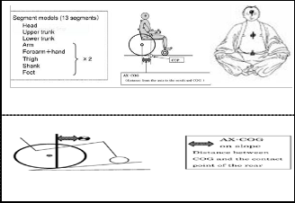
considered separately because the chair’s “COG” is fixed when the following factors are fixed:- Material and design as shown in fig. 2.
Fig. 1. Center of Gravity of human body
Fig. 2. Distance of AX-COG during Slope Propulsion.
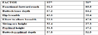
Some other data were taken which are necessary to ensure comfort as shown in table 1.
TABLE 1
ANTHROPOMETRIC DATA
4 RESULTS AND ANALYSIS
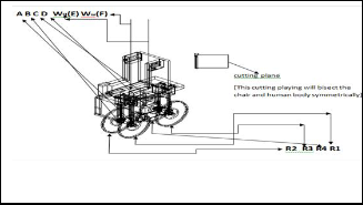
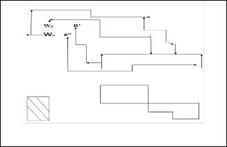
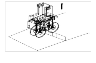
Fig. 3. Free body diagram (of Wheel Chair) subjected to weight of human, Motor, battery and its own.
Now; ∑ Fy=0; so; R1+R2+R3+R4= WH + WW [ R´= R1+R2 and R’’ = R3+R4.]
Here R and R’´ act at the midpoint of AD and BC respectively (P & q).Because of the symmetry of human body and the chair. WH= 154×9.8=Weight of human body. 1000×9.8 =WW=Weight of wheel chair, motor, battery. E= Center of gravity of human body; F= center of gravity of wheel chair (as shown in fig 3). WH is taken based on mean weight of handicaps calculated from a sample of 12 handicaps and injured person. Ww is cal-
IJSER © 2012
http://www.ijser.org
International Journal of Scientific & Engineering Research Volume 3, Issue 4, April-2012 3
ISSN 2229-5518
culated from the materials and design of the chair.
So; R´+R = WH+Ww=11310 N (1)  Mp=0; 0.36×WW + 0.6×WH + 0.9144R =0
So, R”=4966.8N ( 2)
Solving (1) & (2)
R´= 6343.12 N and R = 4966.8N and So; R1=R2=2483.4N& R3=R4
= 3171.56N
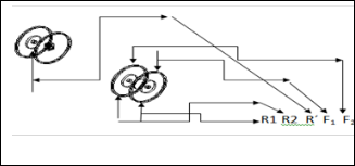
Front wheels
Fig. 4. Front Wheels.
∑FY = 0; SO, F1+F2= 4966.8
∑MA=0; So AB(F1 -R1)=0; So, F1=2483.4N.So; F2= 2483.4N
Wheel connecting Rod

Shearing stress
= Force/Area=F/2πL =.024 Mpa. Here; r= .0381M; L= .43M
Force
Left Leg and Right Leg
σ= F/ A= 0.157 MPa, τ= F/A= 0.09 MPa, δs = 5.17x 10⁻⁷m
δn = 3.14 x 10⁻⁷m; [Here, ∑Fy = 0, so, So, F4+F3=R4+R3.] (3)
∑Mc=0, So, CD (F4- R4)= 0 (4)
From Eqn (3) and (4)
F4 =3171.56 N = F3
Backward/Rear Wheels-Wheel Connecting rod (stress),
τ= 2.253 MPa, σ = 0.099MPa
Ball Bearing for (F3) and (F4)
Circular Disc, τ= 0.8 MPa, Sphere, τ = 0.563325MPa
Wheel (3) and (4)-
Shearing Stress τ = 0.145 MPa; σ =0.06993 MPa
Supporting Plate (F3 and F4) Backward legs
σ = 0.4428 MPa; τ = 2.657 MPa; F3 = F4= 3171.56 N
Stress and deformation on spring τ=284.708 MPa,δ=3.09x 10⁻¹⁶
Load on hollow rectangular support (Left and right)
F= 2481.84N; σ =0.121 MPa; τ = 0.069 MPa; δs = 3.95x 10⁻⁷ m; δn =
2.42x10⁻⁷m
Flexure Stress on Seat
The shear fig 5 showing that maximum Bending moment

hence Flexure stress occurs at point of action of Chair’s weight.
Max M= 4966.8 X0 .36=1787.77 N-M; Max =MaxM/S = 6*
MaxM/ bh2 = (6*1787.77)(0.76*0.132) = 0.88 Mpa
Normal stress σ =

r 2
= 0.187 MPa
Ball-Bearing [At Position k and L]
F1

[(Sphere shape) for F2 and F1] so; stress =
4r 2
F2
= 0.725 Mpa;
stress =

4r 2
= 0.725 MPa
Supporting plate (on ball bearing)
Normal stress, For F1, σ= F1/ A = 0.57MPa, for F2, σ = 0.57 MPa
Shearing stress, (for F1 and F2) = 3.42 MPa ;Deformation, δn=
s d=ev1e.lo0p8ed×o1n 0s ms, δs = =Le1ft./R0i8gh×t l1eg0 m,E=40 Gpa
Fig. 5. Cross-Section and shear diagram.
Dynamics (General and aerodynamics)
∑Fy = 0; So; Ww+Ww= R1+R2+R3+R4


stres
E= (

= 366.42 Mpa
pring
F1 or F2
R = 1.25in
D =5 in
For Movement; ∑Fx≥0

FEolorngcaetionand stress on sprinmg= s = 4
S = G = 83 Gpa = modulus
So, Fs≥ µk (WH + WW) + 0.5 (cd AρV2) ≥ 3393.24 N

Le=f3t.98leg and right leg Force = F1= 3307.82 [Actually F1- (FB+ Fp+
= 83 10 NM
≥ Fs x υ ≥3393.24W
Right leg
9 -2

N = 10
wheel
FH=/3B66).4]2 M(Fpao; rS c= e3.9s89i1n0-1c0mrease while jumping on stairs)
[Here,Fs=Force Supplied, F
k=kinetic frictional force;
stress developed on springs
 =
= (
( 
= 366.42 Mpa
Elongation
S = 
= 3.98x 10⁻¹⁶m
Right leg
τ= 366.42 Mpa ; S = 3.98910-10m
Left/Right leg
F1 or F2
R = 1.25in
D =5 in
m = 2R/d= 4
G = 83 Gpa = modulus of Elasticity
= 83x109NM-2
N = 10
0.5CDAρv2= Aero-dynamic reistance; Cd= 0.50 drag coeffi- cient; A= 0.8 m2; ρ= 1.2 (air); v= 1m/s, µk =0.3]
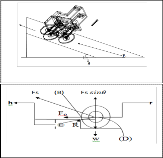
Moving through inclined plane as in fig 6 (For movement)
Fs≥ µk (Ww+ Wh) cosθ + (Ww+ Wh) Sinθ+ Far≥ 11336N Ps= Fs x v≥ 7.59 HP [Where; v=0.5ms-1; θ= 30°; µk= 0.58] Where; v= 0.5ms-1 θ= 45°; µk= 1
Ps≥ 10.72 HP; So increasing the angle of inclination results in more power requirement.
Movement through Inclined Plane (Stairs) as in fig 7
Here a new criteria is developed about the force required to cross an obstacle of a certain height.
Load and stress on hollow rectangular support
Fo×CB> (w- Fs Sinθ) x CD
Fs cosθ x CB > (w- Fs Sinθ)x

2rh h2
IJSER © 2012
http://www.ijser.org
International Journal of Scientific & Engineering Research Volume 3, Issue 4, April-2012 4
ISSN 2229-5518
Fs>(w- Fs Sinθ)x
2rh h2
force requirement. But user can’t ignore the presence of ob-


(r h) cos
2
stacle. So the design is focusing to an optimized approach of
“increasing the wheel radius hence to increase the difference
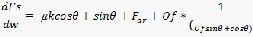
Hence Of= 2rh h
(r h) cos
= Obstacle factor
between radius and height of obstacle”. But this approach would increase the total weight acting in the system. But here it can be proved the increment in radius would not result in a significant change in force requirement but significantly re- duce the total force needed.
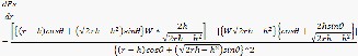
Fig. 6. Moving through incline plane.
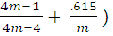
For θ= 30°, r= 7.5 in, h = 5 in, W= 11310N, dFs / dr= -1065.618 N/ in
For θ= 30°, µk= 0.58

dFs
dw
= 2.24
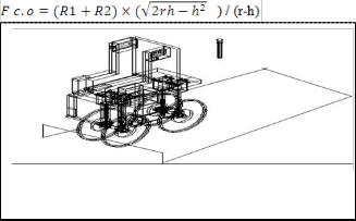
Fig. 7. Movement through inclined plane (stairs)
Here; r=radius of wheel; h= height of obstacle; R=reaction on point of contact; W=weight acting on wheel; Fo =Component of force (Fs) required to cross an obstacle of a certain height. So, radius should be greater than height of obstacle.
Condition –I as in fig-8 (All wheels try to cross the obstacle)
Fs ≥ µk(ww + wh) cosθ+ (ww + wh) Sinθ+ Far+ Fc.o ≥ µk(ww + wh)
But increment of weight is 8.5 N/inch radius increased, so it results in 19.04 N/inch
So, dFs/ dr > > dFs / dw
So, increase the radius within the size restriction. Here power
is calculated in terms of velocity. But moment or Torque is more significant than the velocity because sufficient moment should be generated to overcome an obstacle against the mo- ment due to weight.
Condition of Maximum moment (All wheels try to cross the obstacle) 
Condition-II as like fig 9 (Front wheels try to cross the ob-
cosθ+ (ww + wh) Sinθ+ Far + Of*

ww wh
O f Sin cos
≥ 25367.95N
stacle; Rear wheels moving on flat plane)
For r= 7.5 in, h= 5in, W= 11310N; τs >2031.334N-M
So; Ps ≥10.20 HP; Where, v = 0.3ms-1; θ= 30°; µk= 0.58; h=5 inch;
r =7.5in
Fs ≥ µk(R1 + R2) + Far+ Fc.o≥15546.144 N. So Ps≥10.42 HP
For θ= 30°, r= 7.5 in, h= 5 in, R1 + R2= 4996.8 N; µk= 0.58, V= 0.5.
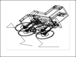
Fig. 9. Condition- II (Front wheels try to cross obstacle, rear wheels moving on flat plane).
Fig. 8. Condition-I (all wheels try to cross obstacle).
Condition of minimum Force hence power supply when weight, angle of inclination and velocity is fixed.
i.e. (dOf / dr) = 0
That indicates the absence of Obstacle would result in lower
Condition-III as like fig 10 (Rear wheels try to cross the ob-
stacle; Front wheels moving on flat plane)
Fs ≥ µk(R3 + R4) + Far+ Fc.o≥ 11544.375N; So, Ps≥7.74HP;
For θ= 30°, r= 7.5 in, h= 5 in, R1 + R2= 4996.8 N; µk= 0.58, V= 0.5
IJSER © 2012
http://www.ijser.org
International Journal of Scientific & Engineering Research Volume 3, Issue 4, April-2012 5
ISSN 2229-5518
Motor Outer Dia=19.69 in and Motor Length= 6 in (App.)
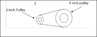
This is the torque input in the smaller 3 inch Pulley. The power is transmitted to a 9 inch larger pulley by a V-Belt which is connected to the rear shaft.
Fig. 10. Condition-III (Rear wheels try to cross the obstacle, front wheels moving on flat plane)
TABLE 2
STATISTICAL DATA FOR ANGLE OF INCLINATION, STAIR HEIGHT AND
WEIGHT
Fig. 11. Motor and its Torque- RPM relation.
Pin=10000 w; τin =1200 N-M, Pout=10000 w (App.) (slip and slack is negligible)
So, Nin = 79.58 rpm, τout =3600 N-M; S0, Nout= 26.5 rpm
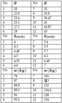
Fig. 12. Power Transmission.
So, velocity of rear wheel V=
2N out * r

60
=0.53 m/s > 0.3m/s(req.), τout= 3600 N-M>2031.334 N-M. These allowances are given due to prevent unknown (without experiment) reverse torque generated due to collision among wheels and stairs.

Voltage Applied to the DC poles; V applied = 273.6 V, Rarme- ture=1.10(Cu);
For 50th Percentile, θ = 30°, h= 5in, w= 98.25 kg; For 95th percentile, θ= 45°, h=
7in, w= 154 kg “[9]”.
5 SOURCE OF POWER AND POWER TRANSMISSION
From the calculation it is found that the pulley connected to wheel should provide power greater than 10.72 HP. A 10kw (Cont.) is utilized here; 273.6 VDC Brushless DC servo motor / torque motor; 273.6 VDC as a power source. Torque motors are frameless kit motors. They consist of a permanent magnet rotor and a laminated stator. Cooling system is provided with Motor [10].
Motor Torque (Cont.) =1200 N-M
P= I. Vcemf= Pout = 1000W; So, I= 44.517 A
Pinput= V applied * I=12180 w (App.) ; Heat generated=I2 *R=2180
w (App.) ; Efficiency =10000/12180=82%(App.); Torque of L.P
= (T1- T2) *r1 =3600 N-M; Torque of S.P = r2 (T1- T2)=1200N-M Here (T1-T2) =31500 N(App.) is the resultant force in the belt. So belt should be selected based on:-
Cross sectional area of V-belt
Max tolerable stress
Stress developed, Torque, RPM
Length
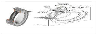
Now A Nickel Metal Hybrid Battery is used as a voltage
hence power source to motor [11].
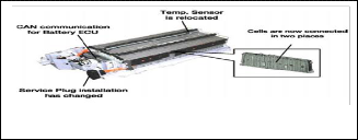
The HV battery pack contains six nickel-metal hydride 1.2V
cells that are connected in series to form one modulle In the
01-03 Prius, 38 modules are divided into two holders and
connected in series. Thus the HV battery contains a total of 228 cells and has a rated volted of 273.6V. The electrode plates in the HV battery are made of porous nickel and metal hydride alloy.
IJSER © 2012
http://www.ijser.org
International Journal of Scientific & Engineering Research Volume 3, Issue 4, April-2012 6
ISSN 2229-5518
Fig. 13. Battery.
Both motor and battery manufacturer provide cooling system. In the present design the facility of containing and circulating cooling fluid (Liquid and air) is provided.
Motor Controller (Features)
Speed Control by Pulse Width Modulating (PWM) only the low-side drivers reduces switching losses in level converter circuitry for high voltage motors.
Open or closed loop motor speed control.
Externally selectable input to output code for 600 1200,
2400, or 3000 electrical sensor spacing.
Three or four phase operation.
Analog Speed control.
Forward/Reverse control.
Output Enable control.
Positive Static Braking.
Overcurrent Sensing.
Six outputs drive switching bridge directly.
Input/output Description: Commutation Selects (Pins 1, 20)
These inputs are used to select the proper sequence of out- puts based on the electrical separation of the motor position sensors. With both inputs low (logic zero), the sequence is ad- justed for 600 electrical separation with CS2 high and CS1 low
1200 separation sequence is selected, with CS1 high and CS2 low 2400 separation sequence is selested and with CS1 and CS2 high the 3000 separation sequence is selected. Note that in all cases the external output drivers are disabled for invalid SENSE input codes. Internal pull down resistors are provided at Pins 1 and 20 causing a logic zero when these pins are left open.
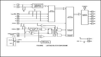
Fig. 16. LS7362.
Recommendation for Electric Cables
EXRAD FX 600 volt shielded battery cable designed specifical- ly to handle the higher voltage and current. The jacket insula- tion isolates any stray currents making this cable very safe. Thin wall and high temperature insulations allow for lower weight and less space. EXRAD FX 600 volt shielded battery cable is able to withstand temperatures of 240°C and higher [13].
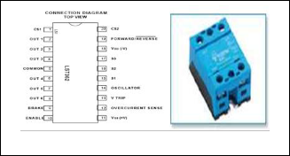
Fig. 17. Electric Cable.
Fig. 14. Motor controllers.
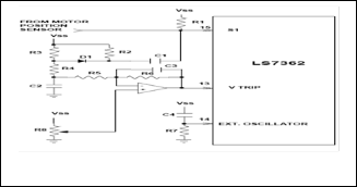
The COMMON, Pin 5, is tied to the positive supply rail and LS7362 Output 1, 2, and 3 are used to drive level converters Q101, Q102 and Q103, respecively. Only the motor top side drivers consisting of Q107, Q108 and Q109 Which are connected to the motor supply, VM, Will be subject to the high speed switching currents that flow through the motor. The level converters are turned on and off at the slower commutation rate.
Fig. 15. Closed loop speed controller.
6 OTHER OPERATIONS
Er=Energy for rotation; EF= Energy for friction; S=r*α; α=π/4;

r=0.216m. For moving the front wheel in an angle =45 deg
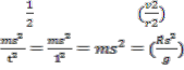
Er= 2× IW2= mn2W2=mr2 =mn2
= = 18.61W
EF = µk * R×s= 323.50W; Et = EF+Er= 342.11W;
This would be supplied from battery by using H-bridge for both rotations. One 1 KW DC motor is used for this operation. Cylindrical Rods standing on Wheel’s shaft are connected with a V-belt Drive Consists of identical pulley to maintain same speed of rotation of both wheels.
H-bridge is an electronic circuit which enables a voltage to be
applied across a load in either direction. These circuits are of- ten used in to allow DC motors to run forwards and back-
IJSER © 2012
http://www.ijser.org
International Journal of Scientific & Engineering Research Volume 3, Issue 4, April-2012 7
ISSN 2229-5518
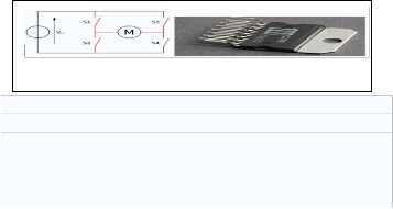
wards [14].

Fig. 18. Structure of an H- Bridge (highlighted in Red).
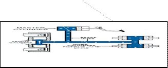
Seat-back angle control
Switching the carriage also include magnetism in magnet and pulls down the lock. Here another electromagnetic mechanism is used by switching control board. we can move the carriage back and fro to get preferred a seat back angle.
Power Needed S= rθ=0.48m
W=FS=31.65J; P=10.54W; [T=3S;F=65.90N(µkR)]
Seat length control
This is not an automatic control. Before starting to use the user
will set the length. The back support is on a rectangular car-
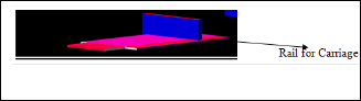
riage which can be moved through a passage containing lock- ing system to set the length in desired positions.
Fig. 19. Seat.
9 MATERIALS
Low cost Grey cast Iron for Body and frame (providing Damp- ing capacity and required load bearing capacity) [16], Respec- tive materials for accessories as recommended, Cotton Foams for seat and Lead free painting and coatings are required.
10 COST ANALYSIS
The costing is for a single automated wheel chair.
TABLE 3
INDIVIDUAL PARTS COST
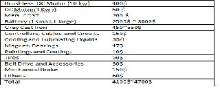
Statements that serve as captions for the entire table do not need footnote letters. By reducing the power requirement (Battery, Motor etc.), Mass production and location of warehouse could be cost reducing factors efficient Sourcing could reduce cost
7 MECHANICAL BRAKES
For safety a mechanical brake is used .It would help the motor brake to stop a heavy load (Big momentum) easily. Hydraulic System is used. It can be controlled by hand.
Fig. 20. Mechanical Brake.
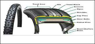
8 TIRES
11 DISCUSSION
The wheel chair was developed by considering different prin- ciples of science and engineering and our innovative ap- proach. But due to high cost we could not test it practically. This is why emphasis was given on developing the theoretical background by considering all known factors which can affect the functioning of the product.
12 CONCLUSION
In developed nations almost all buildings have the facilities of elevators and separate stair ways for wheels. But these facili- ties are rarely found in homes of South Asian, African Nations. A narrow band of customers are focused who can afford to buy this facility of leading a self dependent (In movement) life being a handicap. Further improvement can make this chair more outstanding and to overcome the remaining shortfalls.
Fig. 21. Tire.
Tires are used to make frictional grip to resist slipping because
some user may have tiles fitted in stairs. They are selected based on rating to provide necessary frictional grip hence Coefficient of friction as stated before [15].
IJSER © 2012
http://www.ijser.org
International Journal of Scientific & Engineering Research Volume 3, Issue 4, April-2012 8
ISSN 2229-5518
REFERENCES
[1] M. Halender, “A Guide to the Ergonomics of Manufacturing,” 1st
East-West Edition, Publisher, Taylor & Francis, pp. 21 ~ 23
[2] http://helpguide.org/mental/post_traumatic_stress_disorder_sympto ms_treatment.htm, 2004
[3] G. A. Dugas, "Safer Automatic Wheelchair Wheel Locks," http://en.wikipedia.org/wiki/Motorized_wheelchair, 1993.
[4] www.freepatentsonline.com/4898256.html , 2008
[5] I. Iturrate, J. Antelis, A. K¨ubler and J. Minguez, “Non-Invasive Brain- Actuated Wheelchair Based on a P300 Neurophysiological Protocol and Automated Navigation,” http://webdiis.unizar.es/~jminguez/,
2007
[6] D. Keman, “IBOT wheelchair Stair-climbing wheelchair,”
https://www.msu.edu/~luckie/segway/iBOT/iBOT.html, 2000.
[7] S. Ashahara, “Research work on Combined centre of Gravity of hu-
man and wheelchair,” unpublished
[8] F.L. Singer, “Strength of Materials,” 4th Edition, Harper & Row, Pub- lishers, Inc. , pp. 131~139, 1987
[9] http://en.wikipedia.org/wiki/Percentile, 2009
[10] G. A. McCoy, “Energy-Efficient Electric Motor Selection Hand-
book;Direct Drive Torque Motors for Machine Tool Applications”,
pp. 217-219, 2004
[11] “Toyota Hybrid System” course-071, section-3, pp. 3-1 to 3-8
[12] http://en.wikipedia.org/wiki/LSIComputerSystem-LS7362, 2010 [13] www.champcable.com/pdf/EXRAD-Hybrid , 2009
[14] http://en.wikipedia.org/wiki/H_bridge , 2008
[15] www.bridgestone.co.in/tyre/tyreknowledge/index.asp , 2010
[16] B.K. Agarwal, “Introduction To Engineering Materials,” Tata
McGraw Hill, New Delhi, India, pp. 209~216, 1997
IJSER © 2012
http://www.ijser.org