Fan type : Mixed flow fan
Number of blades : 7
Orientation of blades : Backward inclinedairfoilcrosssection
Internal diameter of the fan : 43mm External diameter of the fan : 233mm Rpm : 2920
Material : frp
Shroud thickness : 4m
International Journal of Scientific & Engineering Research Volume 2, Issue 9, September-2011 1
ISSN 2229-5518
Design of cooling fan for noise reduction using CFD
G.V.R. seshagiri rao, Dr.V.V.subba rao,
Abstract— Cooling fans are one of the main noise sources in pumps. Tonal noise produced at a multiple of the rotational frequency of th e fan, the so-called blade passing frequency (BPF) and its higher harmonics generally dominate fan noise. Noise reduction is perhaps one of the most important parameter in pumps. Every noise reduction process starts with identification of noise sources and ranking of sound sources from the machinery. After the initial identification of typical noise sources, the noise levels are to be eliminated or reduced either by modifying noise producing equipment or redesigning. In the present work, a cooling fan system of a sea water pump is considered. CATIA software is used to model the system and computational fluid dynamics (CFD) techniques are implemented for the analysis. In the first phase, CFD analysis procedure is developed and implemented to the baseline fan to designate the sound levels at inlet and outlet. Experiments are conducted for the same baseline fan in anechoic chamber and noticed high frequencies. The numerical results obtained through CFD are corroborated with experimental results and they are found to be in good agreement. After validating the theoretical procedure, an attempt is made to redesign the existing fan with National Advisory Committee for Aeronautics (NACA) series by way of changing geometrical parameters to reduce noise levels. The nois e levels are computed and compared with the baseline fan results. The redesign fan results indicate that the noise levels are low by 5-10dBs.
—————————— ——————————
Noise is to a great extend, a purely subjective personal phenomena. Perhaps the best definition of it is as an unwanted sound. Noise does, however, have two basic characteristics. The first is the physical phenomenon that can be measured and thus used in technical specification. The second is the psycho acoustical characteristic, which attempts to judge the effect of noise on human beings. In industries that use small cooling fans, fan noise simply interferes with the ability of the people working nearby to concentrate on their work. The factors of greatest importance to the system designer are the psychological influences on the person rather than the physical influences of sound on the human ear. Cooling fan is a device that creates a pressure difference by exchanging momentum from the blades to the surrounding gaseous fluid. The primary purpose of motor fan is to move a required volume flow rate of air. Motor fans should be designed with minimum noise and minimizing the overheating of motor. Fan noise consists of tonal noise, broadband aerodynamic noise, Mechanical noise and motor nose. To reduce fan noise in cost effective manner, it is necessary to incorporate the component of noise reduction into an early design stage.
There are two main types of fans axial and centrifugal. Radial, backward-curved and forward-curved types of fans are mostly used in industrial applications. The radial fan is noisiest and least efficient, but useful for dirty and corrosive flows. The forward- curved fan is least efficient and usually made of lightweight and low-cost materials. The backward-inclined or backward-curved airfoil fan is most efficient, but it is only suitable for clean-air industrial applications because dust and other particles can adhere to the fan blades and cause malfunctioning. The primary purpose of fan is to move a required volume flow rate of air against a given back pressure with maximum efficiency. In the Present problem cooling fan is an axial flow fan of 10 straight blades. It is driven by
14.71 KW (20 HP) electric motor (EM). These motors are used in
submarines for pumping sea water. Noise reduction is perhaps one of the most important areas in optimizing sea water pump, which especially is used for under water applications. As the fan in this application rotates at single constant speed, the investigation is done at only one operating point, which corresponds to the flow
————————————————
Dr.v.v.subbarao is currently working as professor in mechanical
resistance caused by electric motor surface having cooling ribs. The objective of the work is to establish design criteria for the geometry of the fan in order to reduce the noise generated without reducing the fan operating point.
The geometry of the fan test system is constructed in the grid generator (gambit) Fig 1.0 shows part of the model for the base line fan, Fig 2.0 shows meshed fan model. The mesh is exported to the fluent solver and the problem is defined by choosing the appropriate flow model and prescribing the boundary conditions. Fluent uses a control volume based technique to convert the governing equations that can be solved numerically. The principle equation in the CFD models for general viscous flow may be represented by the time averaged Navier-stokes equation.
A complete Computational Fluid Dynamic analysis has been made and the details of the parameters used for analysis are provided for future reference. The noise radiated from the fan at different receiver locations is found out and are plotted. The model used for noise radiated due to the flow of air Ffowcs- Williams and it considers the mean velocities obtained from the CFD analysis to predict the noise radiated from the cooling fan. In this analysis the intention is to see the flow of the fluid and the noise radiated from the fan itself. Moreover the geometry should be supplied with a shielding/-diverting cap to divert the flow smoothly on to the motor. The excitation of the cap may also contribute to the total noise, which is not considered in this analysis. A similar type of fan with bell mouth entry is analyzed with protective / shielding cap and the noise levels are observed in the same range. Since the motor geometry of the motor is considered as rough estimate we can observe a long jump of fluid and a fair amount of swirl as the flow takes place on the motor surface. The information for the integrated fan blade cover system performance is generally lacking from the fan manufacturers test data; i.e., the fan performance, based only on the fan blade design, is provided from the manufacturers.
A commercial CFD software, Fluent, is used to develop the
CFD model. Three- dimensional flow simulations are performed at various fan speeds for a specific fan model. The noise levels are calculated and compared with experimental measurements and fan law predictions to validate the CFD model.
engineering department in Jntu, Kakinada, India. PH-0919440555477. E- mail: rao703@yahoo.com
IJSER © 2011
International Journal of Scientific & Engineering Research Volume 2, Issue 9, September-2011 2
ISSN 2229-5518
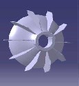
In order to estimate the noise generated by the fan due to fluid flow along the blade passages the first step is to analyze the fluid flow through the fan. This aspect has been proved from the CFD analysis of the impeller. Fig.3 shows airfoil geometry of new designed fan.Fig.4 shows 7 numbers of blades fan. Number of test cases has been run in fluent a commercially available CFD code for the fluid dynamics. Test cases for the mixed flow fan with 7 numbers of aerofoil geometry blades are tested. In the present work, the fluid dynamic analysis for a fan with 7 numbers of blades with constant radius of curvature is performed.
Fan type : Mixed flow fan
Number of blades : 7
Orientation of blades : Backward inclinedairfoilcrosssection
Internal diameter of the fan : 43mm External diameter of the fan : 233mm Rpm : 2920
Material : frp
Shroud thickness : 4m
Fig1. Baseline Fan with 10 Numbers Of Blades
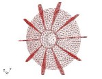
Fig.2. meshed model of baseline fan
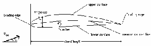
Fig.3 Airfoil geometry
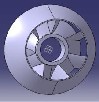
Fig 4.Seven Blades Fan with Aerofoil Geometry of NACA
65-006 Series.
Figure 5.0 shows the experimental set-up for validating the baseline fan with computer model thus developed. The experiments are conducted in an anechoic chamber.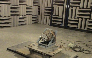
Fig 5.0 Experimental set-up for existed fan to measure noise inside a semi anechoic chamber
An anechoic chamber is a room that is isolated from external sound or electromagnetic radiation sources, sometimes using soundproofing, and prevents the reflection of wave phenomena. Anechoic chambers are widely used for measuring the acoustic properties of acoustic instruments, measuring the transfer functions of electro-acoustic devices, testing microphones and performing psychoacoustics experiments. The main features of an anechoic chamber are SPL measurements, ranking of sound sources, noise source identification and directivity of sound sources and receivers. The measurement point is located at upstream 1 m of the fan inlet, with the microphone aligned to the motor shaft. This is a common location for microphones in test setup.
Fig. 5.0 shows experimental set-up for baseline fan to
measure noise inside an anechoic chamber. The walls, and ceiling are lined with glass-fiber wedges, and the working space in the center of the room is 8 x 8 x 6 m. Room evaluation measurements shows that the room is suitable for measurements from about 125
Hz to 20 kHz.
The result so obtained from numerical analysis is
compared with the experimental results obtained by conducting experiment in anechoic chamber. It is found that there is good agreement between numerical and experimental results which are presented in later sections. It is observed the variation between numerical analysis results and experimental results is 3 to 5 dB. The error between numerical and experimental observed may be due to interference between the rotating blades and shroud, motor- fan casing, noise generated by electric motor, vibration due to unbalanced rotating masses etc. Table 1.0 shows the comparison of the measured and CFD overall SPL values for baseline fan.
IJSER © 2011
International Journal of Scientific & Engineering Research Volume 2, Issue 9, September-2011 3
ISSN 2229-5518
In order to validate the procedure developed is implemented to estimate the noise generated by the fan due to fluid flow along the blade passages the first step is to analyze the fluid flow through the fan. A number of test cases have been run in fluent a commercially available CFD code for the fluid dynamics. Test cases for the mixed flow fan with seven numbers of blades and
10 numbers radial blades are tested.
As per the observation of the experimental data for 10-
blade radial mixed flow fan gives a high noise as developed at inlet and outlet. It is necessary to reduce the systems blade passing frequency (BPF) noise.
The figure 4.0 shows the complete solid model of 7 blades with aerofoil section fan was modeled in CATIA v5 r16 commercial solid modeling package. Test cases for the mixed flow fan with seven numbers of aerofoil shaped blades are tested. The Following Graphsfig.6 & Fig.7 shows Blade thickness noise is generated by volume displacement of fluid. Fan blades have its thickness and volume. As the rotor rotates, the volume of each blade displaces fluid volume, then they consequently fluctuate pressure of near field, and noise is generated. This noise is tonal at the running frequency and generally very weak for cooling fans, because their RPM is relatively low. Therefore, thickness of fan blades hardly affects to cool fan the noise. The tonal noise is affected at initial stage because suddenly fluid is entered into the fan, it show high sound pressure 65 to 95 dBs for all NACA 65 series fans And once the fan rotation is stable it maintains smooth fluid flow and also maintains low noise.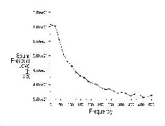
Fig.6. SOUND PRESSURE Vs FREQUENCY OF NACA 65-006 AT RECEIVER 1
Results are presented for the measurement point located at
1 m of the fan inlet, with the microphone aligned to the impeller shaft for baseline fan measurements. Broadband and narrowband noise analysis is carried out for fansat same fan operating point. The operating point corresponds approximately to the best efficiency point (BEP). . Broad band analysis is used to obtain noise spectra in the range of 20–20,000 Hz and narrow band analysis is used to obtain noise spectra in the range 0–5000 Hz.
Fig. 8 shows narrowband sound pressure spectrum of
baseline fan for frequency in the range of 0-5 kHz. Fig. 9 and Fig.
10. Shows the results of 1/3 octave band pressure level for baseline
fan. It can be observed that tonal noise is predominant in low frequency range (0-1000 Hz) only, while broadband noise extends in the entire range of frequency.
The overall Sound Pressure Level (SPL) for baseline fan is
82.3 dB(A). This value is higher because of straight blade design
producing more turbulence. Overall SPL for motor without fan is
61.8 dB(A). From experimental results it is observed that the effect
of motor on total SPL is not significant and the dominant noise
source is motor-fan (dipolar noise source as noise is generated due to aerodynamic pressure fluctuation). These results indicate that the blade of the cooling fan is the main contribution to the aero acoustic characteristics of the flow field.
Fig.8 denotes high peak value of 69.9 dB was observed at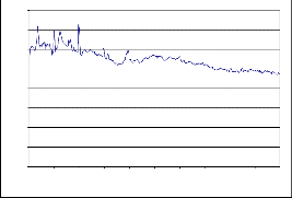
blade passing frequency (BPF) 485 Hz. The tonal aerodynamic noise generated at this frequency is mainly caused by the impeller–motor cooling fins interaction. Besides, another peak value of 72.8 dB was observed at harmonics of blade passing frequency (970 Hz). A high peak at the impeller rotation frequency (RF) 48.5 Hz is clearly shown in Fig. 8. Another peak is observed at 175 Hz, which could be a harmonic of shaft speed. Some of the noise peaks other than at shaft RF, BPF and their higher harmonics, could be due to resonant frequency of the motor-fan casing, noise generated by electric motor, vibration due to unbalanced rotating masses etc. The maximum acoustic radiation is observed on the fan axis. The acoustic pressure level decreases as the listening point is moved away from the fan axis. According to Fig. 8 the harmonics decrease rapidly and present a weak acoustic pressure level.
80
70
60
50
40
30
20
10
0
0 500 1000 1500 2000 2500 3000 3500 4000 4500 5000
Frequency (Hz)
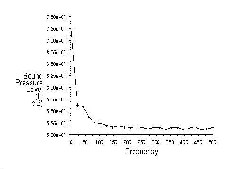
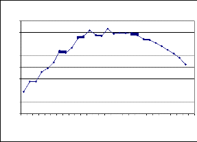
Fig.7. SOUND PRESSURE Vs FREQUENCY OF NACA 65-006 AT RECEIVER 2
IJSER © 2011
International Journal of Scientific & Engineering Research Volume 2, Issue 9, September-2011 4
ISSN 2229-5518
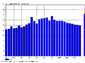
Table1.0 Experimental results of baseline fan
Receiver Position | x (m) | y (m) | Z (m) | Overall SPL dB(A) 125 Hz to 20 kHz |
Receiver Position | x (m) | y (m) | Z (m) | Measurement |
Inlet | 1 | 1 | 0 | 86.4 |
Outlet | -1 | 1 | 0 | 103.3 |
Table2.0 computational results of baseline fan
SOUND PRESSURE SPECTRUM
80
70
60
50 blades)
40
Table 3.0 the computational results of redesigned fan (7
30
20
10
0
FREQUENCY (Hz)
Wide from 40 Hz to 20 kHz
Overall SPL reduction of redesigned Fan is 10 dB (A) compared to baseline fan. It is observed that noise reduction was mainly due to bell mouth entry at inlet and NACA 65-006 aerofoil profile of blade geometry. Table 1.0 Summarize the measured first two discrete sounds and the overall SPL values for baseline fan and redesigned Fan. Table 2.0& Table 3.0 show computational results of Baseline fan and redesigned fan. Finally it is concluded that there was a significant broad band noise reduction obtained with designed Fan. It is observed from Table 4.0 the NACA 65-006 obtains the low noise when compared to other.
Table 4.0 Computational predictions of various NACA
series sound pressures at inlet (1, 1, 0) and outlet![]()
(-1, 1, 0).
IJSER © 2011
International Journal of Scientific & Engineering Research Volume 2, Issue 9, September-2011 5
ISSN 2229-5518
An efficient analysis procedure is developed for the analysis of a cooling fan system using computational fluid dynamics. An anechoic chamber is prepared to conduct experiments. The noise radiated from the fan at different receiver locations is found out and are plotted. It is observed 86.4 dBs at inlet and 103.3 dBs at out let positions.
The sound pressure levels are observed for various NACA
series, it is found that the NACA 65-006, has minimum sound pressure level and they are noted at inlet 64.4 dBs and outlet 72.8 dBs.
The sound pressure levels are observed for the base line fan and prototype model, the noise level is reduced when compare to10 blades radial flow fan.
The receiver positions are increased, the sound pressure is decreased
It is observed the smooth surface body will produce low noise and aerofoil shaped blade helps to reduce noise levels.
The author wish to express his deep sense of gratitude to Dr.v.v.subbarao, professor, jntu, Kakinada,(India) for his valuable guidance and support to complete this paper.
[1] Gutin, L. On the sound field of a rotating propeller. Zhurnal tekhnicheskoifiziki,
1936, Translated as NACA TM 1195 (1948), 6, pp. 899-909.
[2] Lighthill, M. J. On sound generated aerodynamically: I. General theory. Proceedings of the Royal Society (London), 1952, A 211, pp. 564-587.
[3] Curle, N. The influence of solid boundaries upon aerodynamic sound. Proceedings of the Royal Society (London), 1955, A 231, pp. 505-514.
[4] Hubbard, H. H and Maglieri, D. J. Noise characteristics of helicopter rotors at tip speeds up to 900 feet per second. The Journal of the Acoustical Society of America,
1960, 32, pp. 1105-1107.
[5] Bragg, S. L. and Bridge, R. Noise from turbojet compressors. Journal of the Royal
Aeronautical Society, 1964, 68, pp. l-10
[6] Sharland, I. J. Sources of noise in axial flow fans. Journal of Sound and Vibration,
1964, 1 (3), pp. 302-322.
[7] Powell, A. Origin and Characteristics of Sound Generation in Compressors and
Fans. The Journal of the Acoustical Society of America, 1966, 40(5), pp. 1237.
[8] Ffowcs Williams, J. and Hawkings, D. Sound generation by turbulence and surfaces in arbitrary motion. Philosophical Transactions for the Royal Society of London,
1969, A 264, pp. 321–342.
[9] Duncan, P. E. and Dawson, B. Reduction of interaction tones from axial flow fans by suitable design of rotor configuration. Journal of Sound and Vibration, 1974,
33(2), pp. 143-1549.
[10] Boltezar, M., Mesaric, M. and Kuhelj, A. The influence of uneven blade spacing on
the SPL and noise spectra radiated from radial fans. Journal of Sound and Vibration,
1988, 216(4), pp. 697-711.
[11] Quinlan, D. A. and Bent, P. H. High frequency noise generation in small axial flow fans. Journal of Sound and Vibration, 1988, 218(2), pp.225-232.
Cudina, M. Noise generated by a vane-axial fan with inlet guide vanes. Noise control
[12] engineering journal, 1992, 39 (1), pp. 21-30.
[13] Neise, W. Review of fan noise generation mechanisms and control methods. An
International INCE Symposium, 1992, Senlis, France, pp. 45–56.
[14] Maaloum, A., Kouidri, S. and Rey, R. Aeroacoustic performance evaluation of axial flow fans based on the unsteady pressure field on the blade surface. Applied Acoustics, 65 (2004), pp. 367–384.
[15] Kudo, T. Development of Noise-reduction method for radiator fan of automobile.
Japan Society of Mechanical Engineers of Annual meeting Lecture collected papers
in 2004(7), 2004, pp. 75-76.
.
IJSER © 2011