i.e.G(x) =1 + x + x2 + x4 + x5 + x6 + x7 + x11 + x12 + x13.
delay elements. Zeroth row of interleaver becomes the N-1 row in the deinterleaver. 1st row of the former becomes N-2 row of later and so on.
International Journal of Scientific & Engineering Research Volume 2, Issue 7, July-2011 1
Issn 2229-5518
Design and Performance analysis of a 3GPP LTE/LTE-Advance turbo decoder using software reference models
Lohith Kumar H G, Manjunatha K N, Suma M S, C K Raju, Prof.Cyril Prasanna Raj P.
—————————— • ——————————
4G evolution. One of the main advantages of 3GPP LTE is high throughput. For example, it provides a peak data rate of
326.4 Mbps for a 4×4 antenna system, and 172.8 Mbps for a
2×2 antenna system for every 20 MHz of spectrum. Furthermore, LTE-Advance [3], the further evolution of LTE, promises to provide up to 1 Gbps peak data rate. The channel coding scheme for LTE is Turbo coding [4]. The Turbo decoder is typically one of the major blocks in a LTE wireless receiver. Turbo decoders suffer from high decoding latency due to the iterative decoding process, the forward backward recursion in the maximum a posteriori (MAP) decoding algorithm and the interleaving/de-interleaving between iterations. Generally, the task of an interleaver is to permute the soft values generated by the MAP decoder and write them into random or pseudo-random positions.
2 FUNDAMENTALS OF TURBO CODES
In order to explain the proposed Turbo decoder architecture, the fundamentals of Turbo codes are briefly described in this section.
———————————————
Lohith Kumar H G is currently pursuing masters degree program in VLSI
& Embedded Systems in Visveswarayya Technological University, India,
PH-+91-99640 89486.
Email: lohithkumar.hg@gmail.com
Manjunath K N is currently pursuing masters degree program in VLSI &
Embedded Systems in Sri Siddartha Institute of Technology, India, PH-
+91-98447 19520. E-mail: manju23687@gmail.com
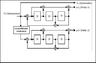
As shown in Fig. 1, the Turbo encoding scheme in the LTE standard is a parallel concatenated convolutional code with two 8-state constituent encoders and one convolutional interleaver [5]. The function of the convolutional interleaver is to take a block of N-bit data and produce a permutation of the input data block. From the coding theory perspective, the performance of a Turbo code depends critically on the interleaver structure [8]. The basic LTE Turbo coding rate is
1/3. It encodes an N-bit information data block in to a code word with 3N+12 data bits, where 12 tail bits are used for trellis termination. The initial value of the shift registers of the
8-state constituent encoders shall be all zeros when starting to encode the input information bits. LTE has defined 188 different block sizes.
The convolutional encoder can be represented as follows [6]:
• g0 = 1 + D + D2 + D3 + D6
• g1 = 1 + D2 + D3 + D5 + D6
The convolutional encoder basically multiplies the generator
Polynomials by the input bit string, as follows:
• A(x) = g0(x) * I(x) = a b c … g
• B(x) = g1(x) * I(x) = P Q R … V
Interleaving the two outputs from the convolutional encoder yields E(x) = aPbQcR … gV, which can also be written as:
E(x) = (a0 b0 c0 … g0) + (0P0Q0R … 0V) = A(x2) +x*B(x2) Therefore, E(x) = A(x2) +x*B(x2) and A(x2)=g0 (x2) +I(x2) and B(x2) = g1(x2) * I(x2), with the following.E(x) = g0(x2) * I(x2) + x * g1(x2) * I(x2)
= I(x2) * (g0(x2) + x * g1(x2))
IJSER © 2011 http://www.ijser.org
International Journal of Scientific & Engineering Research Volume 2, Issue 7, July-2011 2
Issn 2229-5518
= I(x2) * G(x)
Where G(x) = g0(x2) + x * g1(x2)
i.e.G(x) =1 + x + x2 + x4 + x5 + x6 + x7 + x11 + x12 + x13.
delay elements. Zeroth row of interleaver becomes the N-1 row in the deinterleaver. 1st row of the former becomes N-2 row of later and so on.
Fig. 1. Structure of rate 1/3 Turbo encoder in LTE [7]
The basic structure of a Turbo decoder is functionally illustrated in Fig.2. A turbo decoder consists of two maximum a posteriori (MAP) decoders separated by an interleaver that permutes the input sequence. The decoding is an iterative process in which the so-called extrinsic information is exchanged between MAP decoders. Each Turbo iteration is divided in to two half iterations. During the first half iteration, MAP decoder 1 is enabled. It receives the soft channel information (soft value Ls for the systematic bit and soft value
Lp1 for the parity bit) and the a priori information La1 from the
other constituent MAP decoder through deinterleaving to generate the extrinsic information Le1 at its output. Likewise, during the second half iteration, MAP decoder 2 is enabled, and it receives the soft channel information (soft value Ls for a permuted version of the systematic bit and soft value Lp 2 for the parity bit) and the a priori information La2 from MAP decoder1 through interleaving to generate the extrinsic information Le2 at its output. This iterative process repeats until the decoding has converged or the maximum number of iterations has been reached.
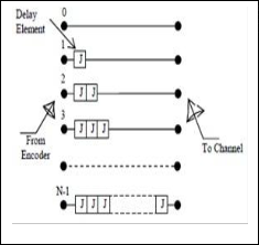
A convolutional interleaver [8] consists of N rows of shift registers, with different delay in each row. In general, each successive row has a delay which is J symbols duration higher than the previous row as shown in Fig. 3. The code word symbol from the encoder is fed into the array of shift registers, one code symbol to each row. With each new code word symbol the commutator switches to a new register and the new code symbol is shifted out to the channel. The i-th (1 � i � N-1) shift register has a length of (i-1)J stages where J = M/N and the last row has M-1 numbers of delay elements. The convolutional deinterleaver performs the inverse operation of the interleaver and differs in structure of the arrangement of
Fig 3: convolutional interleaver [8].
In order to verify the Verilog HDL models for the interleaver and deinterleaver the authors have developed another top level Verilog HDL model, combining interleaver and deinterleaver [8]. The scrambled code words from the output of the interleaver is applied as input to the deinterleaver block along with clock as synchronization signal. It is observed in Fig 4 that the scrambled code word is converted into its original form at the output of the deinterleaver block.
Simulink model of a Turbo Encoder and Turbo Decoder are shown below.
It consists of two convolutional encoders. The outputs of the turbo encoder are the information sequence, together with the corresponding parity sequence produced by first encoder and the parity sequence produced by the second encoder block, the input to second encoder is through interleaver, which scrambles the data bit sequence. Simulation model of Turbo encoder – decoder is shown in
fig 5.
IJSER © 2011 http://www.ijser.org
International Journal of Scientific & Engineering Research Volume 2, Issue 7, July-2011 3
Issn 2229-5518
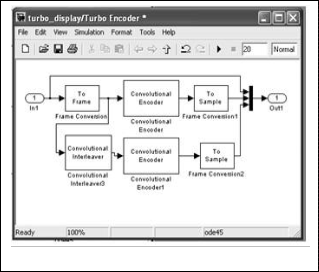
Fig 6: Simulink Model of Turbo Decoder
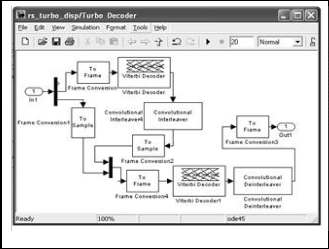
Fig 5: Simulink Model of Turbo Encoder
The proposed Turbo decoder shown above in Fig 6 uses iterative decoding. The turbo code decoder is based on a modified Viterbi algorithm that incorporates reliability values to improve decoding performance. The turbo decoder consists of M-elementary decoders one for each encoder in turbo encoding part. Each elementary decoder uses the Soft Decision Viterbi Decoding to produce a soft decision for each received bit. After an iteration of the decoding process, every elementary decoder shares its soft decision output with the other (M – 1) elementary decoders.
The AWGN Channel [1] block adds white Gaussian noise to a real or complex input signal. Each of the major blocks mentioned above have individual sub blocks which are configured to meet the Specifications (After scaling, keeping in mind the mathematical constraints of modeling a real time system).
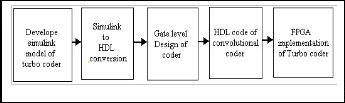
First Simulink model for turbo encoder and Turbo decoder is developed on MATLAB platform. The verilog HDL coding is made on Modelsim and verified. Finally implemented on FPGA, Fig 7 shows the work flow for implementation.
Fig 7: W ork flow for implementation
With the above Turbo encoder, Turbo decoder and channel specifications, the Bit Error Rate (BER) is analyzed for 3 samples per frame; it is 0.000254 so error rate is of order (10-3). The simulink model for turbo encoder and turbo decoder is as shown in Fig.5 and Fig 6. Similarly with the same encoder and decoder specifications are tested for different samples per frame. Here the computation time varies as the number of samples per frame increases; these cases also provide the BER of order 10-3.The obtained results are shown in the Table 1, and the obtained graph is as shown in Fig.8.
Table1: Bits Per Frame Vs Corresponding BER
IJSER © 2011 http://www.ijser.org
International Journal of Scientific & Engineering Research Volume 2, Issue 7, July-2011 4
Issn 2229-5518
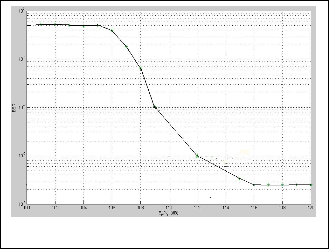
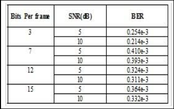
Fig 8: The Plot of BER along y-axis and signal to noise ratio
This work is carried out at MSRSAS, Bangalore as part of final year M.Tech project work. The authors would like to thank the management of RVCE, Bangalore and SSIT, Tumkur for providing support in carrying out their work.
[1] Evolved Universal Terrestrial Radio Access (EUTRA) and Evolved Universal Terrestrial Radio Access Network (EUTRAN), 3GPP TS 36.300.
[2] General UMTS Architecture, 3GPP TS 23.101 version 7.0.0, June 2007.
[3] S.Parkvall, E.Dahlman, A.Furuskar, Y.Jading, M.Olsson, S.Wanstedt, K. Zangi, “LTE-advanced- evolving LTE towards IMT advanced”, in: IEEE Vehicular Technology Conference, September2008,pp.1–5.
[4] Multiplexing and channel coding, 3GPP TS 36.212 version
8.4.0, September 2008.
[5] H. R. Sadjadpour, N. J. A. Sloane, M. Salehi, and G. Nebe,
‘Interleaver design for turbo codes’ IEEE Journal on Selected
Areas in Communications, vol. 19, no 5, pp. 831- 837, 2001.
[6] R. D. Raut, Dr. K.D. Kulat “International Journal of Computer Applications”(0975 - 8887) Volume 1 – No. 24 ©2010 [7]Y. Sun, J.R. Cavallaro,” Efficient hardware implementation of a highly-parallel 3GPP LTE/LTE-advance turbo decoder”, Integration VLSI J. (2010), doi:10.1016/j.vlsi.2010.07.001
[8] B. K. Upadhyaya, S. K. Sanyal “ VHDL Modeling of Convolutional Interleaver- Deinterleaver for Efficient FPGA Implementation”, International Journal of Recent Trends in Engineering, Vol 2, No. 6, November 2009.
In this paper, presented a brief survey about turbo codes, designed a turbo encoder and turbo decoder on simulink and coded in Verilog HDL and implemented on FPGA. The codes and coding techniques are carried by Viterbi decoder. For turbo codes, turbo decoders and their decoding algorithms like log-MAP/SOVA are used. Based on the algebraic constructions, the interleaver offers capability which enables Turbo decoding by using MAP decoders working concurrently. We proposed low complexity recursive architecture for generating the convolutional interleaver addresses on the fly. The convolution interleavers are designed to operate at full speed with the MAP decoders. The proposed architecture has been scaled and can be tailored for different throughput requirements.
IJSER © 2011 http://www.ijser.org