International Journal of Scientific & Engineering Research Volume 2, Issue 5, May-2011 1
ISSN 2229-5518
Design and Development of Fault Tolerent
Control system for an Infant Incubator
Suswetha Parisineti, Eswaran.P
Abstract— This paper proposes the design and implementation of real time monitoring of an infant incubator, based on sensor fault tolerant control system, using a PIC microcontroller. Temperature and humidity are two parameters considered for the design infant incubator. The purpose of a Fault tolerant control systems (FTCS) scheme is to ensure that faults do not result in malfunctioning and system failure and to achieve the of best performance even with minimum number of sensors working. Fault tolerant control systems (FTCS) have ability to detect sensor fault automatically and to isolate faulty sensor which leads to system failure. The fault detection and the isolation (FDI) problem is an inherently complex one and for this reason the immediate goals are to preserve the stability of the process and, if is possible, to control and continue the process in a slightly degraded manner. The role of the FDI algorithms is that the control equipment must automatically isolate the faulted area, to adopt the correct attitude, to generate, to choose and to validate the correct decision. Prototype of infant incubator using FTCS was implemented by using redundant sensor with Build in self test (BIST) facility.
Index Terms— Sensor fault tolerant control, real time based, microcontroller, FTCS.
—————————— • ——————————
HE objective of a fault tolerant control system (FTCS) is to maintain system availability when fault occurs, to improve the reliability of the control system and to
minimize the effects on the system performance and safe- ty [1].
Fault is a kind of malfunction in the system, which may lead to system degradation or any unaccepta- ble performance of the system. The output of the Sensor should be constrained between the lower and upper lim- its, if it crosses these bounds then it is said that the senor is failed.
Fault tolerant control (FTC) has been increasing in the last few years because FTC system has the ability to increase complex systems reliability and performance requirement in the events of faults. The design of a FTC system requires knowledge of advanced control mechan- ism [3]. Systems mostly are very complicated. Designing a FTC system could also be very challenging. Different types of faults such as actuators, sensors, and system faults can occur. Each type of fault requires different ap- proach to work with. A fault tolerant control system must be able to perform, fault detection, fault isolation, and fault diagnosis [3]. FTC should also have the ability to detect faults and provide correction. Fault tolerant control system results on two approaches: active and passive. The active approach relies on fault detection and isolation (FDI) scheme to detect the occurrence of faults in the sys-
————————————————
• Suswetha Parisineti is currently pursuing masters degree program in Embedded system Technologyry, in SRM University, Kattankulathur, Chennai, India. PH-04427452270. E-mail: suswetha.p@gmail.com
• Eswaran.P is currently working as Assistant professor in SRM University,
Kattankulathur, and Chennai, India. PH-04427452270.
E-mail: eswaranp@ktr.srmuniv.ac.in
tem and to identify the source and severity of the faults. Secondly, in passive FTC, potential component faults are known a prior and are all taken into consideration in the control system design stage [5].
Infant incubator provides a controlled environment for newborns needing special care, such as those born prema- turely. By placing an infant in an incubator, doctors and nurses can set and monitor different aspects of the child’s environment in order to create ideal conditions for sur- vival and moreover it protect infants from pollutants and infection[2].
This paper proposes the design and development of microcontroller based temperature and humidity con- troller for an infant incubator monitors and controls these two parameters constantly which are very critical for the normal growth of the new born (premature) babies. Infant incubator is used mainly to keep a baby’s care tempera- ture stable at 37 Celsius and the relative humidity is maintained at (45 to 55)%RH.This system can automati- cally control the infant’s temperature at optimum level and to maintain high relative humidity so as to minimize the thermal loss. The developed system must be user friendly, cost effective and accurate.
Infant incubators and other advances in medical tech- nology have made it possible for small or premature ba- bies to survive in higher numbers than they did in the middle of the 20th century. An incubator is an infant- stimulating system used for intensive care of the new born, premature or sick baby. It provides a safe and clean environment, which has fresh air, clean and sterile am-
IJSER © 2011 http://www.ijser.org
International Journal of Scientific & Engineering Research Volume 2, Issue 5, May-2011 2
ISSN 2229-5518
bient conditions for the babies. In addition to these, the incubator environment provides a homogeneous and sta- ble temperature, a relative humidity (RH) level that are needed especially for intensive care of the premature ba- by.
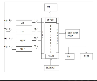
LED’S ( 4 red and 4 green), 8 switches connected, each on either side of the 4 sensors, and a relay board for connection of a fan and a heater. The implementation blockdiagram was shown in the figure 2.
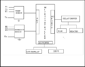
The sensor fault tolerant control was implemented for an infant incubator system. The system mainly consists of the microcontroller along with two temperature sensors, two humidity sensors, switches connected on either side of the sensors, a relay board with fan and heater, an LCD and LED’s for display purpose. The block diagram of an infant incubator is shown in the figure 1.
The input of the sensor ambient condition of infant incubator and the output of the sensor is connected to the analog to digital converter (ADC) of the microcontroller. The microcontroller gets the value from the sensors and then displays in LCD display. The control action is taken by the micro controller to detect which sensor is failed or working properly according to the values taken by the sensors. The LED’s, LCD display and the relay board are connected to the I/O ports of the microcontroller. The heater and fan are connected to the relay board.
Fig.2: Implementation block diagram of an infant incubator
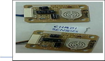
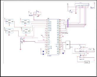
LM35 is an integrated circuit temperature Sensor and CHR01 is an Impedance type humidity sensor are shown in the figure 3 (a), (b). The three pins of LM35 sensors are input pin (is connected to VCC power supply), the output is connected to the ADC of the microcontroller and the ground pin is connected to the ground. ULN2002 used as driver to relay. Through relay load terminals the heater and fan are connected as shown in the figure 4 (a).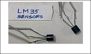
Fig. 1. Block Diagram of an infant incubator.
Temperature and humidity are two very important para- meters that need to be monitored continuously in the infant incubator chamber. Similar environment can be replicated for the pre-term infant or new born baby. Temperature can be displayed in terms of degree Celsius (0C) and humidity in terms of relative humidity which is expressed as % Relative Humidity (%RH).
The PIC16F877A microcontroller chip selected for the purpose of realizing the plant model. The model mainly con- sists of two LM35 temperature sensors, two CHR-01 humid- ity sensors, power supply circuitry, Switching board with 8
Fig.3 (a) LM35 Temperature Sensors
IJSER ©
Fig.3 (b) CHR-01 Humidity Sensor
International Journal of Scientific & Engineering Research Volume 2, Issue 5, May-2011 3
ISSN 2229-5518
.
Fig.4 (a) Circuit diagram of the hardware components in the infant incubator.
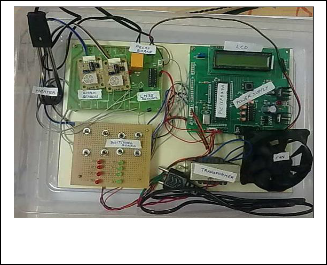
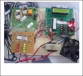
Fig 4 (d) Hardware Implementation of the FTCS for Infant
Incubator
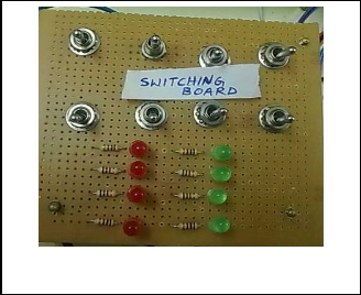
The switching board consists of 8 ON/OFF switches and 8 LEDs used to do self test of FTCS system. Of these 8
LEDs 4 are red LEDs and 4 are green LED’s. Red LED glows, indicate the failure operation and the green LED- glows, indicate the correct and the safe operation and their component layout are shown in the figure 4 (b), (c).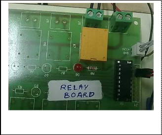
Fig.4 (b) Switching Board practice
Figure 4 (d) shows the complete hardware implemen- tation of the FTCS Infant incubator system.It has micro- controller module, sensors module (two temperature and two humidity sensors), BIST module (sensor switching board), Power supply module, and Load driver module with fan and heater.
Consider,
T1 is the value from the temperature sensor1
T2 is the value from the temperature sensor2
H1 is the value from the humidity sensor1
H2 is the value from the humidity sensor2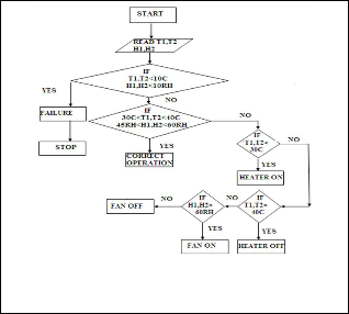
Fig.4 (c): Relay Board.
Fig.4(e) Flow chart of the operation of the Infant Incubator system.
IJSER © 2011 http://www.ijser.org
International Journal of Scientific & Engineering Research Volume 2, Issue 5, May-2011 4
ISSN 2229-5518
TABLE 1
Analysis of the Sensor Fault Tolerant Control System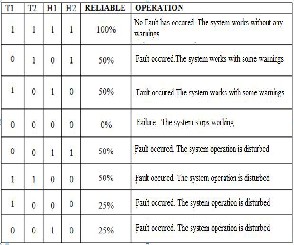
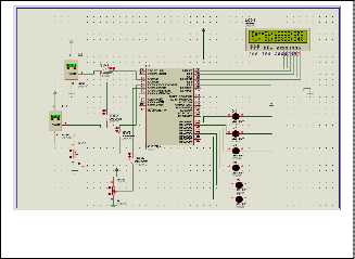
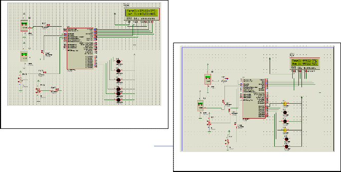
Table 1 shows the sensor conditions for FTCS. The flowchart shown in the figure 4 (e) explains the operation of the sensor fault tolerant control of an infant incubator system. The T1, T2, H1, H2 values are taken from the sen- sors, the microcontroller reads the values and then com- pares them with the upper and lower limits. If it is not within the limit then the heater or fan operations are han- dled. If the values read by the sensors are less then 10 C or 10RH then the sensors are said to be failed. If all the sensors show the error value then the system is said to be a failure one and the operation should be stopped.
Figure 5(a) shows the Simulation results of complete circuit carried out using Proteus software. The results obtained from the PIC16F877A microcontroller interfaced with two temperature sensors, two potentiometers as humidity sensors, an LCD and LED’s. The LCD is used to monitor the sensor readings. The LED’s are also con- nected for identification of the sensor working properly.
Fig.5(b) Hardware of FTCS showing Temperature sensors and
Humidity sensors are working effectively.
The figure 5 (b) shows that the two LM35 temperature sensors and the two CHR01 humidity sensors are work- ing correctly and the system is said to be 100% reliable. The LED’s glowing indicates the sensors are working properly and there is no malfunction in the system. The LCD display shows both the temperature and the humidi- ty sensors values are within the specified range.
Fig.5(c) FTCS Showing One humidity sensor and one tempera- ture senor are isolated.
Fig.5(a) Simulation result showing Temperature sensors and
Humidity sensors are working effectively.
IJSER
Fig.5(d) One humidity sensor and one temperature senor are failed.
International Journal of Scientific & Engineering Research Volume 2, Issue 5, May-2011 5
ISSN 2229-5518
Figure 5 (c) shows that the only one LM35 tempera- ture sensor and the only one CHR01 humidity sensor are working correctly. In that case the system is said to be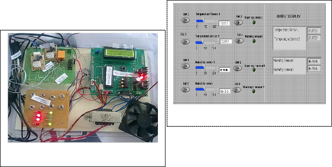
50% reliable. If one of the LED was not glowing indicates the system operation continues with some warnings. The LCD display shows one temperature sensor value and the one humidity sensor value are within the specified range and one temperature sensor value and the one humidity sensor value are not within the range since they are iso- lated.
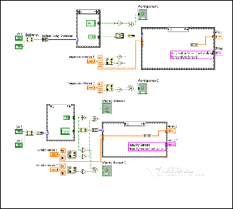
The figure 5 (f), (g) shows the implementation of FTCS infant incubator in LABVIEW environment, that the all the sensors are working effectively and the value dis- played also is within the desired range. So the system works correctly without any error or warnings. The LED glowing indicates the error or failure operation.
Fig.5 (g) Front Panel view of switching operation using LAB- VIEW.
Fig.5 (e) FTCS showing one humidity sensor and one tempera- ture senor are failed.
The figure 5 (d), (e) shows that the only one LM35 temperature sensor and the only one CHR01 humidity sensor are working correctly and one temperature sensor and one humidity sensor are failed. The system is said to be 50% reliable. The LED’s are not glowing indicates the system operation is not disturbed but some warnings are arised. The LCD display shows one temperature sensor value and the one humidity sensor value are within the specified range and one temperature sensor value and the one humidity sensor value are not within the range since they are failed.
Fig.5(f) Block diagram of the switching operation using LAB-
The results are analyzed for different conditions of sensor. If they are not within the desired upper and lower limits then the LED indicating the specific sensor glows as the alarm to inform that the sensor is failed or an error is occurred to the sensor.
6 CONCLUSION
A suitable and realistic sensor fault tolerant control system for real-time implementation on an infant incuba- tor for parameters like temperature and humidity is im- plemented according to the specifications given in Table:1 using the PIC16F877A microcontroller. The system uses the redundancy technique, i.e., if one sensor is failed then the microcontroller considers the value from the other sensor. The FTCS oeration represented by the flowcharts are then translated into equivalent C language and com- piled using MPLAB IDE, the PIC16F877A software devel- opment tool. MPLAB IDE then translates the C files into corresponding hex files which are uploaded onto the PIC16F877A microcontroller. The microcontroller em- bedded with the proposed FTCS for real time implemen- tation. Software Simulation using proteus IDE and circuit was implemented with hardware and tested. Test result shows PIC microcontroller is capable of realizing the FTCS operation.By simulation results were obtained for various input conditions manually, by ON and OFF of the switches connected in series andparallel to the sensors. Using LABVIEW, the operation BIST implemented with the switches is explained for how the LED glows and in- dicates the safe and error and failure operation. The dif- ferent sensor condition are considered and tested. For each and every condition and the output is determined. By various tests infant incubator with FTCS was working effectively and it is observed that the overall system has a
VIEW
R © 2011 http://www.ijser.org
International Journal of Scientific & Engineering Research Volume 2, Issue 5, May-2011 6
ISSN 2229-5518
reliabity of 50%.
[1] Chen, J., Patton R.J. (1999). Robust model based fault diagnosis for dynamic systems. Kluwer Academic Publishers.
[2] Simon BN, Reddy NP, Anand K.A theoretical model of an in- fant incubator dynamics J. Biomech Eng; 116:263-6, 1994.
[3] Patton, R.J. (1997) Fault-tolerant control: the 1997 situation.
Proceedings of the IFAC SAFE PROCESS, 2, 1033-1055.
[4] S. S. Yang, Haider A. F. Mohamed, M. Moghavvemi, P. H. Ng.
Real-time Model Based Sensor Fault Tolerant Control System on a Chip.
[5] Blanke, M., Staroswiecki, M., Wu, N.E. (2001).Concepts and
Methods in Fault- Tolerant Control. Proceedings of the Ameri- can Control Conferences, 4, 2606-2620.
IJSER © 2011 http://www.ijser.org