International Journal of Scientific & Engineering Research Volume 4, Issue3, March-2013 1
ISSN 2229-5518
Design of an Ultrasonic Distance Meter
Md. Shamsul Arefin, Tajrian Mollick
Abstract- There are several ways to measure distance without contact. One way is to use ultrasonic waves at 40 kHz for distance measurement. Ultrasonic transducers measure the amount of time taken for a pulse of sound to travel to a particular surface and return as the reflected echo. This circuit calculates the distance based on the speed of sound at 25°C ambient temperature and shows it on LCD display. Using it, we can measure distance up to 2.5 meters. In this circuit, a 40 kHz transducer is used for measurement in the air medium. In this project, we excite the ultrasonic transmitter unit with a 40 kHz pulse burst and expect an echo from the object whose distance we want to measure. It travels to the object in the air and the echo signal is picked up by another ultrasonic transducer unit (receiver), also a
40 kHz pre-tuned unit.
Index - IC, LED, LCD, Microcontroller, Rangefinder, Transducer, Ultrasonic Sensors.
—————————— • ——————————
1 INTRODUCTION
distance detector is any device capable of measuring the distance between two points. The origins of distance measurement by means of graduated lengths
of material such as chain, tape measure or piece of knotted
rope are lost to antiquity. Optical distance measurement also has a long history, and is usually taken to stem from the work of James Watt in 1771. Electro-magnetic measurements make up a third method, where the time of travel of radio or light waves is converted into a distance. Since James Watt, hundreds of different types of instrument have been produced to make indirect distance measurement using light. All kinds of devices or equipment nowadays, begin with the basic design, basic theory and then all the weakness followed by improvement step by step.
So this project will also do right the same reason which the
improvement will be applied to bring the advantages to the user when measuring the distance depending on several problems that had been identified. The purpose of why this project is being carry out is the ultrasonic technology that is been used for this project because ultrasonic technology is one of the medium on how the distance will be measure and this is one of the ways that the world today widely used especially in some kind of general application such as in warfare applications, engineering applications and also in scientific and medical applications. Basically this ultrasonic technology is based on ultrasound and a common use of ultrasound is in range finding that perfectly related to the objectives of this project. This technology can be used for measuring: wind speed and direction (anemometer), fullness of a tank, and speed through air or water. For measuring speed or direction a device uses multiple detectors and calculates the speed from the relative distances to particulates in the air or water. To measure the amount of liquid in a tank, the sensor measures the distance to the surface of the fluid.
1.1 Project Background
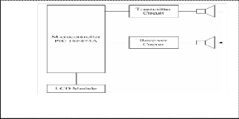
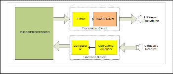
The system consists of only one main component, a microcontroller unit which acts as the brain of the system. Input and output components such as transmitter unit, receiver circuit, temperature control and LCD modules are connected to the system brain. Fig. 1 shows the components of the system and how they are connected. The transmitter generates a 40 kHz signals and begin the transmission time together with the process of sending signals. While the signals begin to transmit through ultrasonic transducer, the microcontroller will capture the starting point of transmission time and hold it until the receiver gets the echo signal back. The signal will contact with any obstacle ahead and will bounce back to the receiver circuit. When the signal is back, the receiver must detect the echo signal, process & send to the microcontroller. The microcontroller will stop the transmission time immediately and will calculate the range using the transmission time and display the range on LCD modules. If the transmit signal cannot touch any obstacle in front it, or the time is very fast, the system will display error message on the LCD modules, indicate the range is not suitable for the system.
Fig. 1. Schematic diagram of Transmitter and Receiver signals.
1.2 Objective
The objective of this work is to replace the old traditional range detector, used in several applications. In present work
IJSER © 2013 http://www.ijser.org
International Journal of Scientific & Engineering Research Volume 4, Issue3, March-2013 2
ISSN 2229-5518
the object position is measured electronically by using seven segment displays by replacing the heavy and bulky circuits with the compact circuits using intelligent Microcontroller. The bulky pressing switch is replaced by the small and one touch tactile switch. It saves electric consumption, saves the no. of man power, through seven segment display and one microcontroller as well as ultrasonic receiver & transmitter sensors.
1.3 Ultrasonic Distance Meter
Ultrasonic distance meter works on a principle similar to radar or sonar which evaluates attribution of a target by interpreting the echoes from radio or sound waves respectively. Ultrasonic sensors generate high frequency sound waves and evaluate the echo which is received back by the sensor. Sensors calculate the time interval between sending the signal and receiving the echo to determine the distance to an object.
This technology can be used for measuring: wind speed
and direction (anemometer), fullness of a tank and speed through air or water. For measuring speed or direction a device uses multiple detectors and calculates the speed from the relative distances to particulates in the air or water. To measure the amount of liquid in a tank, the sensor measures the distance to the surface of the fluid. Further applications include: humidifiers, sonar, medical ultrasonography, burglar alarms and non-destructive testing.
Systems typically use a transducer which generates sound waves in the ultrasonic range, above 18,000 hertz, by turning electrical energy into sound, then upon receiving the echo turn the sound waves into electrical energy which can be measured and displayed. The technology is limited by the shapes of surfaces and the density or consistency of the ma material. For example, from the surface of a fluid in a tank could distort a reading.
1.4 Literature Review
Distance measurement is the activity of obtaining and comparing in our real world. It is one of the important functions in science, engineering and astronomy to business activities. There are many types of distance measurement systems we use in our environment from normal rulers to Interferometer. In applications, basic concept of electronic distance measure system is adopted in many areas like aviation, navigation and many more. In aviation, direct feedback system is required for linear positioning and motion control application. One of the good examples for distance measurement in navigation is GPS system using satellites. So there is no doubt about the usefulness of distance measurement technology in our environment. Reviews of available literature of this project have been performed to ensure more understanding to construct ultrasonic distance meter. The areas that were focused are on behavior of ultrasound through journals, books, and internet. Although many different type of ranging systems available in market, there are only three major type of ranging systems used in technology which are Ultrasonic Ranging System.
2 METHODOLOGY
The technique of distance measurement using ultrasonic in air include continuous wave & pulse echo technique. In the pulse echo method, a burst of pulses is sent through the transmission medium & is reflected by an object kept at special distance. The time taken for the pulse to propagate from transmitter to receiver is proportional to the distance of object. For contact less measurement of distance, the device has to rely on the target to reflect the pulse back to itself. The target needs to have a proper orientation that is it needs to be perpendicular to the direction of propagation of the pulses. The amplitude of the received signal gets significantly attenuated and is a function of nature of the medium and the distance between the transmitter and target. The pulse echo or time-of-flight method of range measurement is subject to high levels of signal attenuation when used in an air medium, thus limiting its distance range.
2.1 Block Diagram

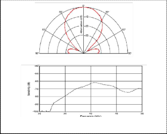
Fig. 2. Graphical Characteristics of Ultrasonic Sensor Ranger
Fig. 3. Block diagram of Ultrasonic Distance Meter
IJSER © 2013 http://www.ijser.org
International Journal of Scientific & Engineering Research Volume 4, Issue3, March-2013 3
ISSN 2229-5518
2.2 Components
For the purpose of making the Ultrasonic Range Meter the following components are used.
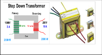
2.2.1 Step-Down Transformer
A step-down transformer accepts a given voltage on the primary winding (coil), and outputs a lower voltage on its secondary winding. A good example is a doorbell transformer we might buy for our home. It uses 120 volts from the house electrical system and steps it down to a safer 18 volts used to ring the doorbell. The voltage produced is a function of the
'turns-ratio' of the transformer. For example, if the transformer has 500 turns of wire in the primary, and 125 turns of wire in the secondary, we would say it has a turn’s ratio of 4:1 (pronounced "four-to-one").If we feed 120 volts into the primary, the secondary would produce 30 volts.120:30 =
4:1Step down transformers are designed to reduce electrical voltage. Their primary voltage is greater than their secondary voltage. This kind of transformer "steps down" the voltage applied to it. For instance, a step down transformer is needed to use 110 V product in a country with a 220 V supply. Step down transformers convert electrical voltage from one level or phase configuration usually down to a lower level. They can include features for electrical isolation, power distribution, and control and instrumentation applications. Step down transformers typically rely on the principle of magnetic induction between coils to convert voltage and/or current levels. Step down transformers are made from two or more coils of insulated wire wound around a core made of iron. When voltage is applied to one coil (frequently called the primary or input) it magnetizes the iron core, which induces a voltage in the other coil, (frequently called the secondary or output). The turn’s ratio of the two sets of windings determines the amount of voltage transformation. An example of this would be: 100 turns on the primary and 50 turns on the secondary, a ratio of 2 to 1.Step down transformers can be considered nothing more than a voltage ratio device. With step down transformers the voltage ratio between primary and secondary will mirror the "turn’s ratio" (except for single phase smaller than 1 KVA which have compensated secondary’s). A practical application of this 2 to 1 turn’s ratio would be a 480 to 240 voltage step down. Note that if the input were 440 volts then the output would be 220 volts. The ratio between input and output voltage will stay constant. Transformers should not be operated at voltages higher than the nameplate rating, but may be operated at lower voltages than rated. Because of this it is possible to do some non- standard applications using standard 10 transformers. Single phase step down transformers 1 KVA and larger may also be reverse connected to step-down or step-up voltages. (Note: single phase step up or step down transformers sized less than
1 kVA should not be reverse connected because the secondary
windings have additional turns to overcome a voltage drop when the load is applied. If reverse connected, the output voltage will be less than desired.)
Fig. 4. Step Down Transformer
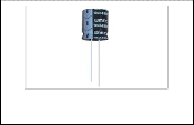
2.2.2 Electrolytic Capacitor
An electrolytic capacitor is a type of capacitor that uses an electrolyte (an ionic conducting liquid) as one of its plates to achieve a larger capacitance per unit volume than other types, but with performance disadvantages. All capacitors conduct alternating current (AC) and block direct current (DC) and can be used, amongst other applications, to couple circuit blocks allowing AC signals to be transferred while blocking DC power, to store energy, and to filter signals according to their frequency. Most electrolytic capacitors are polarized; hence, they can only be operated with a lower voltage on the terminal marked "-" without damaging the capacitor. This generally limits electrolytic capacitors to supply-decoupling and bias-decoupling uses, since signal coupling usually involves both positive and negative voltages across the capacitor. The large capacitance of electrolytic capacitors makes them particularly suitable for passing or bypassing low-frequency signals and storing large amounts of energy. They are widely used in power supplies and for decoupling unwanted AC components from DC power connections.
Super capacitors provide the highest capacitance of any
practically available capacitor up to thousands of farads, with working voltages of a few volts. Electrolytic capacitors range downwards from tens (exceptionally hundreds) of thousands of microfarads to about 100 nano farads—smaller sizes are possible but have no advantage over other types. Other types of capacitor are available in sizes typically up to about ten microfarads, but the larger sizes are much larger and more expensive than electrolytic (film capacitors of up to thousands of microfarads are available, but at very high prices). Electrolytic capacitors are available with working voltages up to about 500V, although the highest capacitance values are not available at high voltage. Working temperature is commonly
85°C for standard use and 105° for high-temperature use;
higher temperature units are available, but uncommon. Unlike
IJSER © 2013 http://www.ijser.org
International Journal of Scientific & Engineering Research Volume 4, Issue3, March-2013 4
ISSN 2229-5518
other types of capacitor, most electrolytic capacitors require that the voltage applied to one terminal (the anode) never become negative relative to the other (they are said to be "polarized"), so cannot be used with AC signals without a DC polarizing bias (non-polarized electrolytic capacitors are available for special purposes).Leakage current, capacitance tolerance and stability, equivalent series resistance (ESR) and dissipation factor are significantly inferior to other types of capacitor, and working life is shorter. Capacitors can lose capacitance as they age and lose electrolyte, particularly at high temperatures. A common failure mode which causes difficult-to-find circuit malfunction is progressively increasing ESR without change of capacitance, again particularly at high temperature. Large ripple currents flowing through the ESR generate harmful heat.
Two types of electrolytic capacitor are in common use:
aluminum and tantalum. Tantalum capacitors have generally better performance, higher price, and are available only in a more restricted range of parameters. Solid polymer dielectric aluminum electrolytic capacitors have better characteristics than wet-electrolyte types—in particular lower and more stable ESR and longer life—at higher prices and more restricted values.
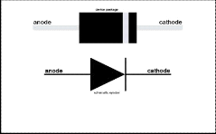
2.2.4 Diode
An electrical device with two active terminals, an anode and a cathode, through which current passes more easily in one direction (from anode to cathode) than in the reverse direction. Diodes have many uses, including conversion of AC power to DC power, and the decoding of audio-frequency signals from radio signals. In electronics, a diode is a two- terminal electronic component with asymmetric transfer characteristic, with low (ideally zero) resistance to current flow in one direction, and high (ideally infinite) resistance in the other. A semiconductor diode, the most common type today, is a crystalline piece of semiconductor material with a p-n junction connected to two electrical terminals. A vacuum tube diode, now used only in some high-power technologies and by enthusiasts, is a vacuum tube with two electrodes, a plate (anode) and filament (cathode).The most common function of a diode is to allow an electric current to pass in one direction (called the diode's forward direction), while blocking current in the opposite direction (the reverse direction). Thus, the diode can be viewed as an electronic version of a check valve. This unidirectional behavior is called rectification, and is used to convert alternating current to direct current, including extraction of modulation from radio signals in radio
receivers—these diodes are forms of rectifiers.
Fig. 5. An Electrolytic Capacitor
2.2.3 7805 Voltage Regulator IC
7805 is a voltage regulator integrated circuit. It is a member of
78xx series of fixed linear voltage regulator ICs. The voltage source in a circuit may have fluctuations and would not give the fixed voltage output. The voltage regulator IC maintains
2.2.5 LCD QY-1602A
Fig. 7. Diode
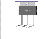
the output voltage at a constant value. The xx in 78xx indicates the fixed output voltage it is designed to provide. 7805 provides +5V regulated power supply. Capacitors of suitable values can be connected at input and output pins depending upon the respective voltage levels. Fig. 6 shows the 7805 voltage regulator IC.
Fig. 6. 7805 Voltage Regulator IC
Short for liquid crystal display, a type of display used
in digital watches and many portable computers. LCD displays utilize two sheets of polarizing material with a liquid crystal solution between them. An electric current passed through the liquid causes the crystals to align so that light cannot pass through them. Each crystal, therefore, is like a shutter, either allowing light to pass through or blocking the light. Monochrome LCD images usually appear as blue or dark gray images on top of a grayish-white background. Color LCD displays use two basic techniques for producing color: Passive matrix is the less expensive of the two technologies. The other technology, called thin film transistor (TFT) or active-matrix, produces color images that are as sharp as traditional CRT displays, but the technology is expensive. Recent passive-matrix displays using new
CSTN and DSTN technologies produce sharp colors rivaling
IJSER © 2013 http://www.ijser.org
International Journal of Scientific & Engineering Research Volume 4, Issue3, March-2013 5
ISSN 2229-5518
active-matrix displays. Most LCD screens used in notebook computers are backlit, or transmissive, to make them easier to read.
maximum working voltage of the resistor. Practical resistors have a series inductance and a small parallel capacitance; these specifications can be important in high-frequency applications. In a low-noise amplifier or pre-amp, the noise characteristics of a resistor may be an issue. The unwanted inductance, excess noise, and temperature coefficient are mainly dependent on the technology used in manufacturing the resistor. They are not normally specified individually for a particular family of resistors manufactured using a particular technology.[1] A family of discrete resistors is also characterized according to its form factor, that is, the size of the device and the position of its leads (or terminals) which is
relevant in the practical manufacturing of circuits using them.
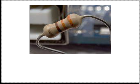
Fig. 8. LCD QY-1602A
2.2.6 Resistor
A resistor is a passive two-terminal electrical component that implements electrical resistance as a circuit element. The current through a resistor is in direct proportion to the voltage across the resistor's terminals. This relationship is represented
by Ohm's law:
Fig. 9. Resistor
2.2.7 Microcontroller
A microcontroller is a small and low-cost computer built for the purpose of dealing with specific tasks, such as displaying

I=
R
(1)
information in a microwave LED or receiving information
from a television’s remote control. Microcontrollers are mainly
Where I is the current through the conductor in units of
amperes, V is the potential difference measured across the conductor in units of volts, and R is the resistance of the conductor in units of ohms. The ratio of the voltage applied across a resistor's terminals to the intensity of current in the circuit is called its resistance, and this can be assumed to be a constant (independent of the voltage) for ordinary resistors working within their ratings. Resistors are common elements of electrical networks and electronic circuits and are ubiquitous in electronic equipment. Practical resistors can be made of various compounds and films, as well as resistance wire (wire made of a high-resistivity alloy, such as nickel- chrome). Resistors are also implemented within integrated circuits, particularly analog devices, and can also be integrated into hybrid and circuits. The electrical functionality of a resistor is specified by its resistance: common commercial resistors are manufactured over a range of more than nine orders of magnitude. When specifying that resistance in an electronic design, the required precision of the resistance may require attention to the manufacturing tolerance of the chosen resistor, according to its specific application. The temperature coefficient of the resistance may also be of concern in some precision applications. Practical resistors are also specified as having a maximum power rating which must exceed the anticipated power dissipation of that resistor in a particular circuit: this is mainly of concern in power electronics applications. Resistors with higher power ratings are physically larger and may require heat sinks. In a high-voltage
circuit, attention must sometimes be paid to the rated
used in products that require a degree of control to be exerted by the user.
2.2.7.1 PIC Microcontroller
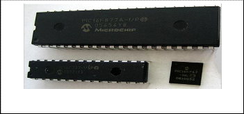
PIC is a family of modified Harvard architecture microcontrollers made by Microchip Technology, derived from the PIC16F72ISP originally developed by General Instrument's Microelectronics Division. The name PIC initially referred to "Peripheral Interface Controller". PICs are popular with both industrial developers and hobbyists alike due to their low cost, wide availability, large user base, extensive collection of application notes, availability of low cost or free development tools, and serial programming (and re- programming with flash memory) capability. They are also commonly used in educational programming as they often come with the easy to use PIC legislator' software.
Fig. 10. Microcontroller
2.2.8 12 MHz Crystal Oscillator
IJSER © 2013 http://www.ijser.org
International Journal of Scientific & Engineering Research Volume 4, Issue3, March-2013 6
ISSN 2229-5518
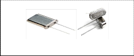
An oscillator is something that produces an output that repeats regularly. In the electronics field this will be an electrical waveform, often but not always a sine wave. The most important property of an oscillator is its frequency the rate at which the output repeats. This is measured in Hertz (Hz for short). One Hertz is one repetition per second. One Megahertz (MHz) is one million repetitions per second. One of the problems in designing a high quality oscillator is maintaining the output frequency at the value required. One method is to control it by a quartz crystal; this is cut so that it vibrates mechanically at the design frequency, and is coupled to the electronics by the piezoelectric effect. A 12 MHz crystal oscillator is an electronic circuit, whose output frequency is controlled by a quartz crystal to repeat 12 million times per second.
Fig. 11. 12 MHz Crystal Oscillator
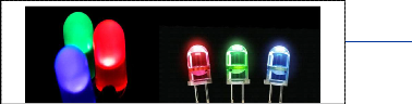
2.2.9 Light-Emitting Diode (LED)
A light-emitting diode (LED) is a semiconductor light source. LEDs are used as indicator lamps in many devices and are increasingly used for other lighting. Appearing as practical electronic components in 1962 early LEDs emitted low- intensity red light, but modern versions are available across the visible, ultraviolet, and infrared wavelengths, with very high brightness. When a light-emitting diode is forward- biased (switched on), electrons are able to recombine with electron holes within the device, releasing energy in the form of photons. This effect is called electroluminescence and the color of the light (corresponding to the energy of the photon) is determined by the energy gap of the semiconductor. An LED is often small in area (less than 1 mm2), and integrated optical components may be used to shape its radiation pattern.[6] LEDs present many advantages over incandescent light sources including lower energy consumption, longer lifetime, improved physical robustness, smaller size, and faster switching. LEDs powerful enough for room lighting are relatively expensive and require more precise current and heat management than compact fluorescent lamp sources of comparable output.
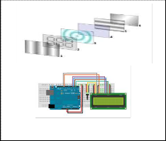
2.2.10 Ultrasonic Sensors
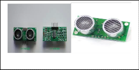
Ultrasonic sensors (also known as transceivers when they both send and receive) work on a principle similar to radar or sonar which evaluate attributes of a target by interpreting the echoes from radio or sound waves respectively. Ultrasonic sensors generate high frequency sound waves and evaluate the echo which is received back by the sensor. Sensors calculate the time interval between sending the signal and receiving the echo to determine the distance to an object. This technology can be used for measuring: wind speed and direction (anemometer), fullness of a tank and speed through air or water. For measuring speed or direction a device uses multiple detectors and calculates the speed from the relative distances to particulates in the air or water. To measure the amount of liquid in a tank, the sensor measures the distance to the surface of the fluid. Further applications include: humidifiers, sonar, ultrasonography, Burglar and testing. Systems typically use a transducer which generates sound waves in the ultrasonic range, above 18,000 hertz, by turning electrical energy into sound, then upon receiving the echo turn the sound waves into electrical energy which can be measured and displayed. The technology is limited by the shapes of surfaces and the density or consistency of the material. For example foam on the surface of a fluid in a tank could distort a reading.
Fig. 13. Ultrasonic Sensors
3 DESIGN PROCEDURE
The circuit has been divided into two divisions.(i) Digital section- micro controller and LCD display unit with 5volt power supply (ii) Analog section – (a) Transmitting side -
Ultrasonic transducers, gain amplifier using analog switch.
IJSER © 2013 p://www.ijser.org
International Journal of Scientific & Engineering Research Volume 4, Issue3, March-2013 7
ISSN 2229-5518
(b) Receiving side - TL084 comparator, gain amplifier, voltage limiter. (c) +15V and -15V power supply.
Fig. 14. Basic Block Diagram
3.1 Construction of Project
The microcontroller closes the switch for duration of 250 microseconds to allow 10 cycles of 40 kHz sine wave. The sine wave varying between 0-1V passes through the switch to the gain Amplifier. The level shifter and gain amplifier gives a sine wave with output varying between -10V and +10V. The transmitter sends out a burst of 10 pulses. As the transducers are directional they are positioned to face the target. The microcontroller waits to receive the pulses for a maximum duration of 12 milliseconds. This is the time taken for the ultrasound waves to travel a maximum distance of 4 meters (time of flight gives twice the time taken to traverse a unit distance). If it doesn’t receive the pulses within this time it is considered as absence of object or object out of range. Once the pulses are received the microcontroller counts 10 pulses with a time spacing of 25 microseconds only then the measurement is considered valid and the computation using the formula is implemented. Necessary hex to decimal conversion and decimal to ASCII conversions are performed to be play the output of the computation in the LCD. The appendix gives the detailed program with necessary comments for this application.
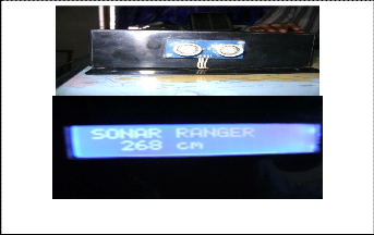
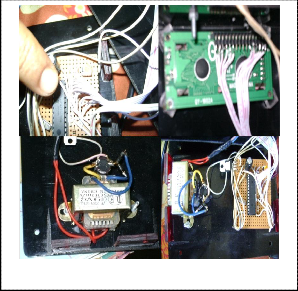
Fig. 16. Project set up pictures
4 PIC PROGRAMMING
// Software for ultrasonic distance meter
// PIC16F72
// Crystal/ 4MHz
// Ultrasonic Sensor
#include <16F72.h>
#use delay (clock=4000000)
#fuses XT, NOWDT, PUT, NOPROTECT
#byte PORTA = 0x05
#byte PORTB = 0x06
#byte PORTC = 0x07
#byte TRISA = 0x85
#byte TRISB = 0x86
#byte TRISC = 0x87
#byte ADCON1 = 0x9F
// Signal port = RC3
// Input switch to start = RC4
// OUTPUT PORT FOR LED = RC2
#define _IO_SIGNAL PORTC.3
#define _D_SIGNAL TRISC.3 sbit LCD_RS at RB1_bit;
sbit LCD_EN at RB2_bit; sbit LCD_D4 at RB4_bit; sbit LCD_D5 at RB5_bit; sbit LCD_D6 at RB6_bit; sbit LCD_D7 at RB7_bit;
sbit LCD_RS_Direction at TRISB1_bit; sbit LCD_EN_Direction at TRISB2_bit; sbit LCD_D4_Direction at TRISB4_bit; sbit LCD_D5_Direction at TRISB5_bit; sbit LCD_D6_Direction at TRISB6_bit; sbit LCD_D7_Direction at TRISB7_bit;
// End LCD module connections
void main()
{
Fig. 15. Project set up pictures
unsigned int EchoTime = 0, Distance = 0;
unsigned char Text[10];
IJSER © 2013 http://www.ijser.org
International Journal of Scientific & Engineering Research Volume 4, Issue3, March-2013 8
ISSN 2229-5518
PORTA = 0; PORTB = 0; PORTC = 0; ADCON1 = 6; LCD_Init();
Lcd_Cmd(_LCD_CLEAR);
Lcd_Cmd(_LCD_CURSOR_OFF); LCD_Out(1, 1, "SONAR RANGER ");
// wait time for initialize Sonar Module
Delay_ms(100);
while(1)
{
5 RESULTS & DISCUSSIONS
5.1 LCD Reading
// set signal to Lo
_IO_SIGNAL = 0;
_D_SIGNAL = 0;
// send start signal for Tout time
_D_SIGNAL = 1; Delay_us(5);
_IO_SIGNAL = 0;
_D_SIGNAL = 0;
// wait for Thold time
Delay_us(750);
_D_SIGNAL = 1;
// clear counter EchoTime = 0; Distance = 0;
// count echo time, every count equal 3us
while(_IO_SIGNAL == 1){ EchoTime++; }
// substract 37*3 = 111us(minimum distance) from
EchoTime
EchoTime -= 37;
// every 20*3us equivalent to 1 cm
Distance = EchoTime / 2000;
// show on LCD WordToStr(EchoTime, Text); LCD_Out(2, 1, Text); LCD_Out_CP(" mm");
// give delay before next measurement
Delay_us(200); Delay_ms(500);
}
}
Fig. 17. Distance Measurement with Scale and Ranger
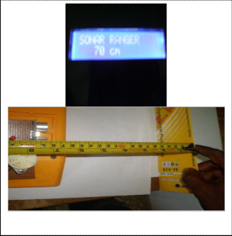
Table 1
Measurement data with scale and Ranger
RANGER | SCALE |
26cm | 29cm |
32cm | 34cm |
49cm | 49cm |
57cm | 68.5cm |
5.2 Control System
The ultrasonic transducer board will link to ultrasonic transmitter port and receiver port. The board is simply mounting the transducers and no Circuit components are integrated. Main circuit board consists of Power supply circuit (240V, 12V and 5V), Microprocessor circuit, Transmitter circuit and Receiver circuits integrated together. Controller circuit is only a mounting board to install Start and Reset Switches and One status indicating LED.
5.3 Discussions
During the final week of the project, the performance measurement was conducted. However, the ultrasonic distance detector could measure a distance less than 500 cm. Due to space constrains, the device was only tested on 200 cm
range without any obstruction. The observation was that, the
IJSER © 2013 http://www.ijser.org
International Journal of Scientific & Engineering Research Volume 4, Issue3, March-2013 9
ISSN 2229-5518
ultrasonic distance detector gave an LED Indication when the object was too near around less than 10 cm. The long range of distance performance need to fine tune as the result performance is not good enough.
6 CONCLUSION & RECOMMENDATION
6.1 Conclusion
The objective of this project was to design & implement an Ultrasonic Obstruction Detection & Distance Measurement device. As described in this report a system is developed that can detect objects & calculate the distance of the tracked object. With respect to the requirements for an ultrasonic rangefinder the followings can be concluded.
• Th e sy st e m i s a b l e t o de t e c t ob j e c t s wi t h i n t h e
sen sing range.
• Th e sy st e m c a n c a l c u l a t e t h e di st a n c e of t h e ob st r u c t i on wi t h sufficient accuracy.
• This device has the capability to interact with other peripheral if used as a secondary device.
• This can also communicate with PC through its serial port.
• This offers a low cost and efficient solution for non-contact type distance measurements.
The R angef i nder has numer ous a ppli ca ti ons. I t ca n
b e u se d f or a u t o ma t i c guided vehicles, positioning of
robots as well as measuring generic distances, liquid levels in tanks, and the depth of snow banks. The device can serve as a motion detector in production lines. The ultrasonic detection range relates with size, figure, material and position of the object. The bigger the reflector is, the better the reflectance is, and the stronger the reflection signal is. The ultrasonic distance measurement is an untouchable detection mode. Compared with else detection modes, it does not get much influenced by ray, temperature and color etc, and it has the great capability to adapt to various circumstances and ambient conditions. A restricted target angle (it requires a near perpendicular surface) & large beam, which can create poor resolution, seem to be the Rangefinders’ only limitations. Also there is a blind area and distance limitation in ultrasonic distance measurement. Despite these drawbacks, we find the device’s main features to be extremely useful.
6.2 Recommendation
After the design was implemented and tested, we would like to recommend a few areas for future improvement. The Temperature Control, Circuit Board Implementation, Installation of On-Board Programming Circuit is several ideas and modifications that can be improved the performance of this system in the future.
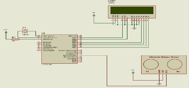
7.1 Main Board Schematic Diagram
7 APPENDIX
IJSER © 2013 http://www.ijser.org
International Journal of Scientific & Engineering Research Volume 4, Issue3, March-2013 10
ISSN 2229-5518
8 REFERENCES
[1] Spasov Peter, Microcontroller Technology the 68HC11 and 68HC12
Upper Saddle River, Pearson Prentice Hall, Fifth Edition, 2004.
[2] Sinclair Ian R. and Dunton John, Practical Electronic Handbook, 6th
Edition, 2007.
[3] Horton Ivor, Beginning C, Wrox Press Ltd, Birmingham, U.K, 2nd
Edition, 2002.
[4] Brown Forrest John, Embedded Systems Programming in C and
Assembly, Van Nostrand Reinhold, N.Y, Prentice-Hall, 2003.
[5] Deshmukh V Ajay, Microcontrollers Theory and Applications,
New Delhi, Tata McGraw-Hill Publishing Co. Ltd, 2005.
[6] Microchip Technology PIC 16F87XA Data Sheet
(www.microchip.com,2002)
————————————————
Md. Shamsul Arefin is currently working as a Lecturer in EEE department in IBAIS University, Dhaka, Bangladesh. He completed his B.Sc. degree in EECE from MIST, Dhaka, Bangladesh. E-mail: arefinshamsul1@yahoo.com
Tajrian Mollick is currently pursuing Master’s degree program in Information
& Communication Technology in IICT, BUET, Dhaka, Bangladesh. E-mail:
evu_eece@yahoo.com
IJSER © 2013 http://www.ijser.org