Email: jagmehender@gmail.com
International Journal of Scientific & Engineering Research, Volume 4, Issue 6, June-2013 235
ISSN 2229-5518
Sonia Sharma, Jagmehender Sheoran, Om Prakash Goswami
Abstract-In this paper, a new open ended Quadrifilar Helical Antenna (QHA) is proposed. A Quadrifilar Helical Antenna with parasitic helical strips for circular polarization. The mutual coupling effect between the grounded helical strips and the feeding helical arms provides a good impedance match and wider hemispherical coverage. The impedance bandwidth corresponding to VSWR < 2 is 200 MHz, from 2.28 GHz to 2.48 GHz. This antenna is design on FEKO software and prototype model is tested for the transmission of voice, video and different digital data with satisfactory results. This antenna works well for wi- fi signals reflected off from building and moving vehicles. This antenna is small in size, low cost, and light in weight. Quadrifilar helix antennas are used in the lower microwave band, from L-band to X- band. Typical applications are for TT&C-links in satellites and narrow band data links. The other applications are in GPS- receivers, both in satellite based and ground based systems.
Index Terms: Cardiod, Circular Polarization, Helix, hemispherical coverage, QHA, S-Band, Satellite Communication
The Quadrifilar Helix Antenna (QHA) invented by Gerst [1], consists of four tape helices equally spaced circumferentially on a cylinder and fed with equal amplitude and in phase quadrature of 0°, 90°, 180° and 270° as shown in fig.1[2]. All methods employed for phase quadrature involves couplers created using microstrip line. A branch line coupler produces two equal magnitude outputs ±90 out
of phase and could be used in combination with a ±180 or rat race hybrid which produces two equal magnitude outputs ±180 out of phase to produce the desired phase shift [3].The top view of QHA is shown in fig.2. The quadrifilar helix antenna can transmit and receive circular polarized signals over a large angular region. Its radiation characteristics are determined mainly by the shape of the helices, i.e. the number of turns, pitch angle, antenna height and antenna diameter, and for conical shaped helices also the cone angle. These are typically fixed in space by winding them on some substrate of dielectric material, or by etching them on a substrate which is then formed into a cylinder. Helical antennas offer
many advantages over dipole structures. Helical antennas are compact because of its cylindrical geometry .The antenna's which offers good gain factor and can operate over wideband. The unique property of circular polarized radiation pattern makes them more suitable for satellite communication. A helical antenna can also be used as a feed for a parabolic dish for higher gains [4].
Sonia Sharma received her M-Tech degree in ECE in 2011, from Manv Rachna International University. Her research areas include Patch, Fractul antenna and Log periodic antenna. She has worked for Nokia speech data base project at KIIT collge of Engineering, gurgaon. She is working for miniturisation of antenna.
Email: soniasharmamr@gmail.com
Om prakash Goswami received his B.Tech degree in ECE in
2009, from G.L.A. institute of engineering and technology,and persuing his M.Tech from KIIT collge of Engineering, Gurgaon His research area include patch, Log periodic antenna, antenna miniturisation and he is working for DWT based OFDM systems.
Email: om9837@gmail.com
Jagmehnder Sheoran has received his diploma in Electronics in 2001. His research interest includes PLC control, Pneumatics and electrical control systems for industries. He has worked for Nokia speech data base project at KIIT college of Engineering, Gurgaon. He is also working on very low beam width antennas for high power transmission from satellite.
The QHA, while typically fed as an
unbalanced antenna, is best considered a balanced structure. The opposing filars tend to form a dipole like structure. The two separate pair of filars fed in phase quadrature forms a
hemispherical circular polarized radiation pattern [5]. It is capable of radiating a cardiod shaped, circularly polarized pattern [6]. There are a number of different types QHA
IJSER © 2013 http://www.ijser.org
International Journal of Scientific & Engineering Research, Volume 4, Issue 6, June-2013 236
ISSN 2229-5518
including the multi-turn backfire, self-resonant and fractional-turn QHA. Fractional turn helices are used on board satellites due to their cardiod shaped and circularly polarized radiation patterns [7].The backfire helix can be realized by extending the multi-turn QHA to an integral number of turns results in excellent circular polarization as well as shaped beam. The QHA can either be shorted at the top [6] of the antenna or left open [8]. Almost all helical antennas are designed with uniform diameter and turn spacing. Long helical antennas requires variations in diameter and spacing over the length of the antenna, similar to the optimized Yagi- Uda antenna for very high gain which has varied element lengths and spacing in between the elements [4]. Antenna radiation characteristics can be changed by varying the antenna’s physical parameters and using various materials in helical antenna design. Helical antenna provides good axial ratio and precisely measures the polarization of the received signal due to immunity of the circularly polarized wave to Faraday rotation of the signal propagating through the ionosphere. In addition to circular polarization, helical antennas offer the advantage of high gain in axial direction over a wide range of frequencies which makes them suitable for applications in broadband satellite communications.[9]
The QHA can be described according to a
number of parameters.
Number of turns, N: The number of revolutions each helix of the QHA makes. The performance of the QHA is greatly affected by the number of turns. The QHA with the lower number of turns has better VSWR.
Pitch: The distance between the same points on the consecutive turns of each element. The QHA with pitch less than 0.6 λ has good performance. The desired cardiod shaped is commonly found in QHA having mid range pitches. High antenna gain and good axial
ratio over a broad frequency band are easily achieved by various designs of helical antenna which can take many forms by varying the pitch angle.[9]
Radius Rh: The radius of the circular by QHA. At a set pitch the performance of antenna varies with radius. The VSWR of the antenna
improves for increased radius. The QHA with lower pitch has good overall performance for all radii.
The helix dimensions are targeted for a center frequency of 2.37 GHz and different parameters from 2.28 to 2.48 GHz.. The schematic of the QHA is shown in fig.1. The numbers of turns, N of QHA are 1.018 with QHA radius, Rh of 8.631mm shown in fig.2.
The wire diameter of the antenna, D is 633.9 um with ground plane radius, Rg of 17.26 mm.The QHA height, Hh and height of feed points, Hf are 69.79 mm And 1.328 mm respectively. The antenna is right handed circularly polarized.
The performance of the quadrifiler helix antenna depends on the number of turns, pitch and radius of the antenna. The number of wires in helical antenna is used to control the directivity pattern of the antenna. Monofilar and multifilar helical antennas are the most widely proposed antennas in satellite communications systems because of circular polarization. The proposed antenna covers
2.28 GHz to 2.48 GHz on VSWR <2.0. A QHA with bandwidth of 200 MHz is designed and simulated which gives a good overall gain. The crossed dipoles and reflectors used for different applications provide circular polarization. Quadrature feed used in QHA gives phenomenal results for receiving good noise immune signal.
IJSER © 2013 http://www.ijser.org
International Journal of Scientific & Engineering Research, Volume 4, Issue 6, June-2013 237
ISSN 2229-5518
The low simulated VSWR result is shown in
Fig.3 which is 2 or <2.0 from 2.28 GHz to
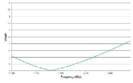
2.48 GHz. At center frequency, 2.37 GHz the value of VSWR is 1.04. The value of impedance for the antenna is about 52Ω as shown in Fig 4. The Fig.5 shows the reflection coefficient which is below -10db for the specified range and the value of reflection coefficient is -31 db at 2.37 GHz. Other results such as different pattern, 3-D pattern are shown in Figs. 6 to 9. Table 1 shows physical parameters of the antenna.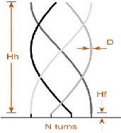
Fig.1: Schematic Open Ended Quadrifilar Antenna
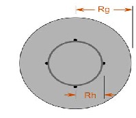
Fig. 2 Top view of QHA
Fig.3 VSWR
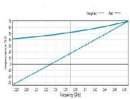
Fig. 4 Impedence
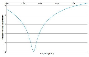
Fig. 5 Reflection Coefficient
IJSER © 2013 http://www.ijser.org
International Journal of Scientific & Engineering Research, Volume 4, Issue 6, June-2013 238
ISSN 2229-5518
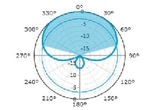
Fig.6 Horizontal Gain 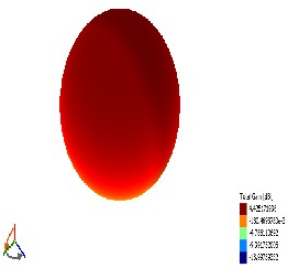
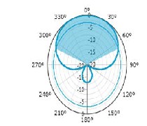
Fig. 9 3D Radiation Pattern
TABLE 1
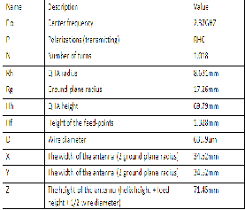
Physical parameter of antenna
Fig.7 Vertical Gain
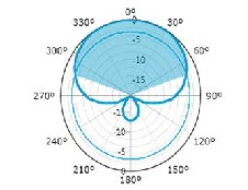
Fig. 8 Total Gain
We would like to express our indeptness to Prof. N.K.Agarwal (HOD, ECE, KIIT)retired Scientist Indian Space Research Organization, Thiruvananthapuram (India) for his kind
assistance, support and valuable insight.
IJSER © 2013 http://www.ijser.org
International Journal of Scientific & Engineering Research, Volume 4, Issue 6, June-2013 239
ISSN 2229-5518
[1] Printed Square Quardrifiler Helix Antennna (QHA) for GPS receiver , Korea advanced institute of science and technology (KAIST), Deajeon, Korea.
[2] C.Gerst, Multifilar contrawound helical antenna study and analysis, Surveillance Technology Study and Analysis, vol. 1
Technical Report.
RADC- TR -67-145, May.1967 and vol.2, Final Report, Feb. 1967. [3] C.Gerst and R.A. Worden, Helix Antenna Take Turn for the Better. Electronics, August 100-110, 1966.
[4] Helical Feed Antennas Paul Wade
W1GHZ©2002w1ghz@arrl.net
[5] Quadrifilar Helical Antennas for Personal Satellite Terminals
Frank M. Caimi, Ph.D.Greg O’Neill September 2004
[6] Peter Berlin. Satellite Platform Design. Kiruna Space and
Environment Campus, 2003.
[7] Helical Antennas in Satellite Radio Channel Maja Škiljo and
Zoran Blažević University of Split, Faculty of electrical
engineering, mechanical engineering and naval architecture, Croatia
[8] Josaphat Tetuko Sri Sumantyo, Koichi Ito, and Masaharu Takahashi. Dual-Band Circularly Polarized Equilateral Triangular- Patch Array Antenna for Mobile Satellite Communications. IEEE Transactions on Antennas and Propagation, 53(11):278–280, November 2005
[9] Lan, C. W., Chang, T. H. & Kiang, J. F. (2004). Helical antenna for GPS applications, Proceedings of IEEE Antennas and Propagation Society International Symposium, ISBN 0-7803-8302-
8, June 2004.
IJSER © 2013 http://www.ijser.org