Inte rnatio nal Jo urnal o f Sc ie ntific & Eng inee ring Re se arc h, Vo lume 3, Issue 2, February -2012 1
ISS N 2229-5518
Design of Data Acquisition System Implemented with a Free Cooling Unit (FCU) Controller
For a BTS Room
Sadeque Reza Khan, Ahmed Al Mansur, Alvir Kabir, Md. Modasshir, Ahmed Al Marouf
—————————— ——————————
Free Cooling Unit is a ventilation system dedicated to the tele- com BTS [1]. The main objective of free cooling is to reduce AC run time and save electricity cost at the BTS sites [2]. It also can reduce the carbon emission as like as the IVS (Intelligent Ventilation System) used in Robi, another leading telecom operator in Bangladesh which is really an environment frien d- ly feature [3].
A special feature is now added with this ventilation system
which is data acquisition. Data acquisition systems, as th e-
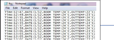
name implies, are products and/or processes used to collect information to document or analyze some phenomenon [4]. So by using this data logger system we can store millions of data of BTS room temperature as well as outside temperature in- cluding the relevant date and time and also can collect those data for further analysis and improvement.
So Free Cooling Unit (FCU) controller is a microcontroller based electronic system that maintains the overall environ- ment of a BTS room by controlling a Fan Unit, a Filter Unit and an AC by observing the room temperature and ba ttery voltage level of a BTS room. It also contains a data acquisition unit using SD card [5].
The FCU is made up of the following major components;
Controller Unit: Controller Unit monitors the whole environ- ment of the BTS room and manages the room temperature by controlling the Fan Unit, Filter Unit and the Air Conditioner. It also contains a data logging section.
———— ——— ——— ——— ———
Ahmed Al mansur is currently pursuing PhD degree in EEE in I slamic
University of Technology, Bangladesh, E-mail: mansur.iut@gmail.com
Alvir Kabir is with the dept of ETE in University of Liberal Arts Bangla-
desh (ULAB), E-mail:alvirkabir@gmail.com
Md. Modasshir is with the dept. of ETE in ULAB,Bangladesh,E -mail:
Ahmed Al Marouf is currently pursuing BSc in CSE in IUT, Bangladesh.
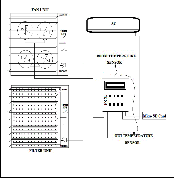
Fig. 1. Total Free Coo ling Unit (FCU) system proposed by Banglalink
Fan Unit: This equipment first opens the louver by using a twelve volt DC motor when a Fan Run Signal comes from the controller. The rotation of the motor is conjusted in a certain level using limit switch. Fig. 1 shows the total FCU system proposed by Banglalink.
IJSER © 2012
Inte rnatio nal Jo urnal o f Sc ie ntific & Eng inee ring Re se arc h, Vo lume 3, Issue 2, February -2012 2
ISS N 2229-5518
Filter Unit: Filter Unit also opens the louver initially as same as the Fan Unit. Next it maintains a dust free air circulation in the BTS room.
Air Conditioner (AC): Although it is not the part of a FCU but still its operation is maintained by the Controller Unit. Now-a- days most of the BTS do not contain a n AC as well.
Most of the BTS rooms contain battery of 48 volt or 24 volt DC to give suppot when the PDB is unavailable. So it is necessary to convert this 48 volt or 24 volt DC to a 12 volt DC to run the controller circuit. This power supply is used to run the motor of the louver as well as it give support to the 5 volt DC section of the controller. We can easily convert the 12 volt DC to 5 volt DC by using LM7805 IC. Fig. 2 shows a power supply section.
For measuring the temperature, FCU controller required two LM35DZ sensors shown in fig. 3. One is for the room tempera- ture and another is used to measure the outdoor temperature. The LM35 series are precision integrated-circuit temperature sensors, whose output voltage is linearly proportional to the Celsius (Centigrade) temperature [8]. Temperature is directly measured by the AN0 and AN1 pin of microcontroller IC.
Battery voltage level monitoring section shown in fig. 4 is one of the important part of this device. In this section we have used a 5kohm multiturn which provides fine resistance a d- justment [9]. So we can monitor the battery voltage level of a BTS room precisely.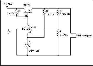
Fig. 4. Battery Voltage monitoring Section
Fig. 2. Pow er supply section
It is a special feature of this contoroller. It works as an external watchdog timer which can reset the whole system when ever it enters in to a forever loop. It is designed with HEF4047B which is an astable or monostable multivibrator IC [6] and used as an edge detector in this section.
The control module is built with the microcontroller IC. The central controller is Microchip PIC18F4520 . PIC18F4520 is an enhancaed flash microcontroller with a 10 bit A/D converter and nano technology [7]. It consists of 36 I/O (Bi directional lines) with 25mA current in per pin. It also has 13 channel built-in A/D converter and 32kbytes of program memory.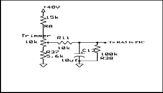
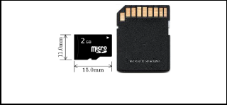
To store the room temperature and outdoor temperature data consecutively a micro SD card shown in fig. 5 is used with an adapter in this controller. The microSD memory Card is a functionally compatible with the SD Memory Card but is smaller in dimensions [10]. The microSD memory Card com- munication is based on an advance 8-pin interface and the microSD memory Card host interface supports regular SD or miniSD Memory Card Adapter and operates as an SD Memo- ry Card. The capacity of micro SD/TransFlash memory cards currently range in storage size from 64 MB (megabytes) to 8GB (gigabytes) and upward [11]. In this project a 2GB micro SD card is used and to interface the SD card with PIC18F4520 an adapter is also used.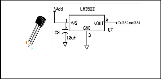
Fig. 5. Micro SD card and Adapter
Fig. 3. Pin Conf iguration and Connection diagram of LM35DZ
For display section a 4x20 line LCD (Liquid Crystal Display) is used. LCD is now a very common choice for graphical and alphanumeric displays. Generaly LCD is a high contrast con- trol module with a 4-bit or 8-bit data bus and built in tempera-
IJSER © 2012
Inte rnatio nal Jo urnal o f Sc ie ntific & Eng inee ring Re se arc h, Vo lume 3, Issue 2, February -2012 3
ISS N 2229-5518
ture control module [12].
tence, as in
(1)
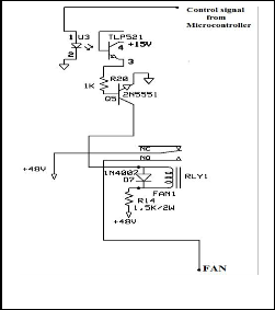
This section is designed to provide a 48 volt battery voltage to the Fan Unit when it is required shown in fig. 6. This is ex- ecuted by the main controller through the logic execution.
Fig. 6. Fan Driving Section
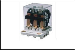
For AC driving a 3-phase 120 ampere DC relay is used which operates at the coil voltage of 12 volt shown in fig. 7.
Be sure that the symbols in your equation have been de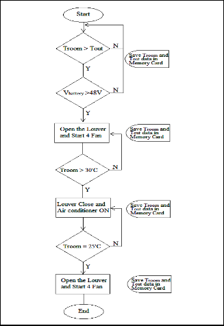
Fig. 7. AC Driving Relay [13]
To open the hood of the louver a low RPM (atleast 10 RPM) motor is used whose operating voltage and direction is con- trolled by the main controller shown in fig. 8.
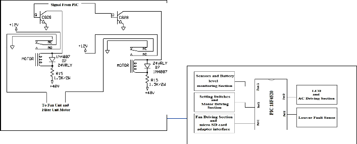
The PIC microcontroller 18F4520 always senses the room tem- perature and outdoor temperature using its 10 bit A/D con- verter. It also monitors the battery voltage level as well. It is important because the Fan Unit will not work if the BTS ba t- tery voltage is under some certain specified level. The control- ler also maintains the room temperature under a predeter- mined value by controlling the Fan Unit and Filter unit opera- tion. It also controls the movement of louver. If the BTS room temperature is not under a tolarent level then the controller gives priority to AC rather than Fan and Filter Unit. One of the major operations of this controller is to store the room temper- ature and outdoor temperature data with relevant time and date in to a micro SD card. Fig. 9 shows the overall system.
Fig. 8. Motor Driving section
SER © 20
:// www.ijse
Inte rnatio nal Jo urnal o f Sc ie ntific & Eng inee ring Re se arc h, Vo lume 3, Issue 2, February -2012 4
ISS N 2229-5518
The experimental setup of the controller unit is shown in fig.
10. One LCD display is used to display time, date, tempera- ture and other required outputs. Fig. 11 shows four fans and the filter unit. Filter unit always helps to filter dust and other unwanted particals.
Fig. 12. LCD Output
Fig. 10. Practical setup of the Controller Unit
Fig. 11. Fan Unit and Filter Un it
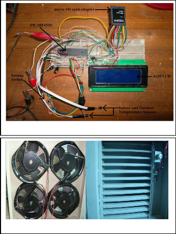
Fig. 12 shows the digital display results in the LCD display. In the display unit it shows the inside and outside temperature of the BTS room. The controller unit takes the necessary action to cool the BTS room by using cooling fans.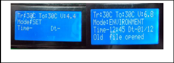
FCU is an environment friendly ventilation system for BTS rooms. It not only reduces the emission of carbon-di-oxide (CO2) in environment but also saves electricity in a great deal. The whole package of FCU is not very costly and it could be an affordable choice for a developing country like Bangladesh. Its data acquisition s ystem is an advance feature which not only helps to monitor the BTS room environment but also can provide ideas how to improve the function of the FCU system. So replacing an Air Conditioner with a Free Cooling Unit will be a profitable choice for our environment and economy as well.
[1] kk_Free_Cooling_FC-T5,_FC-T2,5_ENG v3.0.pdf, [Online], Availa- ble: www.telzas.com
[2] Free cooling.pdf, Bharat Sanchar Nigam Ltd.New Delhi.
[3] Michael Kuehner, “Roby of Bangladesh reduces CO2 emission by 30 percent in 2010”, 2011-06-21.
[4] Data Acquisition Systems, [Online]available: www.omega.com
[5] Dogan Ibrahim, “ SD Card Projects Using the PIC Microcontroller”, www.elsevier.com.
[6] HEF4047B, “MSI Monostable/astable multivibrator”,Jan 1995.
[7] PIC18F2420/2520/4420/4520 , Microcontrollers with 10-Bit A/D
and nanoWatt Technology”, 2007 Microchip Technology Inc.
[8] LM35, “Precision Centigrade Temperature Sensors”, Natinal Semi- conductor, November 2000.
[9] Multiturn vs. Single-turn, http://www.bourns.com/archive.aspx
[10] Shafik G. Punja & Richard P. Mislan, “Mobile Device Analysis”, SMALL SCALE DIGITAL DEVICE FORENSICS JOURNAL, VOL. 2, NO. 1, JUNE 2008 ISSN# 1941 -6164
[11] MicroSD Card Rev1.01, www.pqi.com.tw
[12] LCD MODULE 4x20 - 3.73mm, Available: www.lcd-module.de
[13] Electromagnetic-Relay, Available: www.sungko.com
R © 2012