International Journal of Scientific & Engineering Research, Volume 6, Issue 5, May-2015 1577
ISSN 2229-5518
Design and performance of a Cutting CO2 laser for industrial non-metallic materials
N. Aboulfotoh Ali1 *, H. A. El- flaah2
.
1 Department of Engineering Physics and Mathematics, Faculty of Engineering, Tanta University.
2 Researcher at Military Technical College, Cairo, Eygpt
* Nehal Aboulfotoh Ali: nehalzr@gmail.com, Nehal.ali@f-eng.tanta.edu.eg
Abstract— The great interest in carbon dioxide lasers stems from their continuous power capability, high efficiency and ease of construc- tion. The CO2 laser is a gas type laser with a wavelength of 10.6μm in infrared region. Their high efficiency and tremendous power output have made them one of the most commonly known transition wavelength facilitates laser cutting, drilling and marking of a wide variety of materials in the electronics and medical industries. The CO2 laser we constructed is a low cost laser. The operating voltage applied to the laser is 12 KV, and the power output is in the range of 10-22 Watts .Many of laser design parameters strongly interact with one another, and requires consideration of how they interact to reach the optimum design. The construction of a CO2 gas discharge laser with a glass laser tube design as well as clear housing is presented. Operation was characterized in power, cutting speed and stability over a long time. The results indicate a good operation, optimum powers and beam quality with maximum speed. The experimental results show marking and cutting effi- ciently of different non-metallic industrial materials such as paper, plastic, glass, texture with different thickness.
Index Terms— CO2 laser, design, cutting,experimental, marking, nonmetallic material, optimization,
—————————— ——————————
1 INTRODUCTION
he CO2 laser is comparable in simplicity, if not in size, to the microwave klystron. Both have a high- Q electromag- netic cavity, a highly efficient power-output coupling tech- nique, and an active medium fed from a simple dc power supply. Also, with slight modifications either can be used as an oscillator or an amplifier. The possibility of using molecular vibrations for laser action was clearly pointed out by Polanyi in 1961 [1]. More recently, Patel, C. K. N. [ 2] has described in some detail the laser action on the vibrational-rotational (V-R) transitions of CO2 in an electrical discharge. Shortly after- wards, progress towards high power and efficiency was achieved by Patel with the addition of N2 and with the addi- tion of He. Other molecular systems have been made to lase, but so far CO2 is the most important power producer. Many parameters affect the design and operation of the CO2 laser. The gas discharge can be powered with dc, ac, RF, repetitive pulses, or any combination thereof. The mirrors can be fixed, rotated for Q-switching, or vibrated for reactive Q-switching [4], [5]. Witteman W J. reported The CO2 laser most common- ly known laser for cutting, drilling and marking of a wide va- riety of materials in the electronics and medical industries Ready, J. F. [6] reported that important innovations to be made in commercial CO2 laser technology, particularly in the low and medium power ranges. This work examine the strong dependence of the parameters of the resonator and the condi- tions of a ray launched inside the resonator parallel to the op-
tical axis remains inside the resonator, directly with the output
power. The laser was designed and constructed out of glass and is contained in a suitable casing so that all of its function- ing components can be observed. The laser simply plugs into a standard outlet and from 10 to 25 Watts of coherent, mono- chromatic laser radiation is produced, enough to burn paper and wood. The calculations for an optical resonator and the prediction of the output power was conducted, for an indus- trial CO2 laser that combine high reliability and low operating cost.
2. EXPERIMENTAL WORK
2.1. Determination of output power
Approximate maximum output power of CO2 laser operating in an optimized condition with respect to gas ratio, pressure, and tube current can be calculated if design data on the optical cavity and laser tube are known.

Where, P is the output power of laser in watts, the total cavity loss equal 1, T is the fractional transmission of output coupler, α is the gain coefficient, and l is active length (length of dis- charge providing gain), in centimeters. The diffraction loss of a Gaussian laser beam of radius w when it passes through an aperture with a radius r is given by
,where, the radius r is the radius of the cavity ap- erture, when it located near the spherical mirror, and beam radius w is defined as the spot size of the beam on that mirror.
IJSER © 2015 http://www.ijser.org
International Journal of Scientific & Engineering Research, Volume 6, Issue 5, May-2015 1578
ISSN 2229-5518
2.2. The laser cavity
The system consists of discharge tube, electrodes, mirrors, cooling system, gas system and power supply as shown in figure 1. The function of an optical cavity is to ensure that the light waves generated have the required shape and spacing. The design adopted cylindrical gas discharge tube of length
0.85 m, shown in Figure 2. The glass discharge tube was de- signed from Pyrex glass to operate under high temperature conditions, with two feed-through for cooling jacket (diameter
46 mm) in order to circulate the cooling water around the tube. The bore diameter and length of the discharge were chosen to be 13 mm and 0.6 m respectively, the diameter de- pends on the ultimate operation, according to the curves relate the gain (dB/m) and the discharge current (mA) for different bore diameters [7], and the length was picked from the tables on the bases of the output power [8]. The suitable output cou- pler transmission relative to discharge length and tube diame- ter is 65% [7].
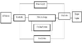
Figure 1 Schematic diagram for typical CO2 laser system
The stainless steel electrodes in this system which with- stand high temperatures with good electrical conductivity are fixed in Teflon holder. Figure 3. shows the electrode holder dimensions and design. The cylinder electrode has length of 80 mm, outer diameter 14 mm and inner diame- ter 13 mm.
Figure 2. Sketch of the discharge tube
The gas inlet part was made of copper with diameter 4 mm to deliver the gas mixture to the tube. Construction of the laser was kept simple to reduce expense and excessive consumption
of time. The simplest optical resonator consists of a pair of plan or spherical mirrors located opposite to each other as shown in figure 4.They are aligned to a common optical axis and are perpendicular to this axis. This cavity has a zinc sele- nide plane mirror output coupler and an enhanced gold rear copper mirror [9] is used as a highly reflector of curvature ra- dium. The design incorporates a laser bore nested in a water cooling jacket, with a feed through the water jacket so that the discharge can go to an external cathode and anode, having the external electrodes lower than the axis of the laser bore reduc- es the possibility that sputtering or oxidation will contaminate the optics [10-11]. The chiller temperature could be adjusted at (15C°) and pumped towards the cooling jacket tube with pumping rate (10-15 Liters /minute). Using deionized water in a closed loop cooling to make the laser self-contained [14].
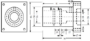
Figure 3. Schematic diagram for the electrode (dimensions are in mm)
Figure 4 Laser tube and resonator scheme
Water inlet and outlets are positioned so that air bubbles which from inside the water jacket are ejected as they rise to the top of the tube. Without this design, air buildup inside the jacket would create a radi- al temperature differential, detuning the resonator and/or thermally poisoning the gain medium [12-13].
The gas supply system consists of a premixed mixture of Carbon dioxide, Nitrogen and Helium. The used ratio is (6 % CO2 – 13.5% Nitrogen – 80.5% Helium) [15] .To control the vacuum and the gas
pressure, two solenoid valves were used, through the paths of evacu-
IJSER © 2015 http://www.ijser.org
International Journal of Scientific & Engineering Research, Volume 6, Issue 5, May-2015 1579
ISSN 2229-5518
ation and filling.
The high voltage power used is optimized for use in mid-power car- bon dioxide and similar laser applications. A high voltage transform- er supplies an alternating voltage (at the power line frequency - 50 or
60 Hz) of 12 kV, 20 mA was used in the system. The output of the
transformer was controlled by using a variable autotransformer (Var- iac) to power the system. Figure 5. is a schematic diagram showing the whole CO2 laser system.
Figure 5. Schematic diagram of the CO2 laser system
2.3. Laser operation and optimization
After the laser system assembled and aligned, it has been test- ed for vacuum. The lowest vacuum value obtained was about
0.2 m bar. The laser tube was then filled to a nominal pressure of (10 mbar) for initial operation. Several attempts were car- ried out for discharge tests with different pressure and voltag- es.
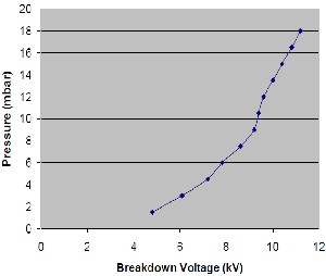
Figure 6. Relation between Pressure and Breakdown Discharge Voltage
Lasing action is now repeatably attainable. Figure 6 shows the
range of pressure and breakdown discharge voltage necessary for continuous, homogenous discharge in the tube. The in- crease of the discharge voltage means the increase in the pres- sure and that lead to increase the output laser power to a cer- tain limit. It is difficult to separate completely the influence of the various parameters on the output power of CO2 laser. The current and the pressure have primarily effect. As the current increases the laser output increases steadily to maximum value and then decreases slowly as the current exceeds its optimum value which depends in turn on gas pressures. Gas mixture pressure plays a dominant role in the configuration of laser output power.
(a)
(b)
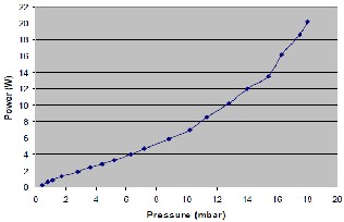
Figure 7. (a) Laser output power as a function of the discharge voltage,(b)
laser output power as a function of the pressure.
TABLE 1
EFFECT OF THE DISCHARGE VOLTAGE ON THE PRESSURE AND OUT-
PUT POW ER
Voltage (kV) | Pressure (mbar) | Power (W) | Vo ltage (kV) | Pressure (mbar) | Power (W) |
3 | 0.4 | 0.2 | 8 | 8.8 | 5.9 |
3.5 | 0.8 | 0.6 | 8.5 | 10.2 | 7 |
4 | 1.1 | 0.9 | 9 | 11.3 | 8.6 |
4.5 | 1.7 | 1.3 | 9.5 | 12.8 | 10.2 |
5 | 2.8 | 1.9 | 10 | 14 | 12 |
5.5 | 3.6 | 2.4 | 10.5 | 15.4 | 13.5 |
6 | 4.4 | 2.8 | 11 | 16.3 | 16.2 |
6.5 | 5.2 | 3.3 | 11.5 | 17.5 | 18.6 |
7 | 6.3 | 4 | 12 | 18 | 20.2 |
7.5 | 7.2 | 4.7 | - | - | - |
The gas pressure is a function of the applied discharge volt- age. Figure 7. (a) illustrates the relation between laser power and charging voltage, while figure (b) represents the laser output power as a function of the pressure. The results shows the direct relation between the output power with both volt- age and pressure. The minimum voltage that produces output
IJSER © 2015 http://www.ijser.org
International Journal of Scientific & Engineering Research, Volume 6, Issue 5, May-2015 1580
ISSN 2229-5518
power of 0.2 W was found to be 3kv. Table 1. Summarize the values of pressure and voltage necessary for continuous, ho- mogenous discharge in the tube and maximum measured output laser power for each value.
3. WORKING SETUP FOR CUTTING
The parameters that affect the cutting process and can be al- tered in order to improve the quality of the cutting process and achieve the required cutting results; include beam geome- try, beam intensity, and laser beam focusing. However, some process parameters are normally not altered by the operator.
CW laser beam is preferred for smooth, high cutting rate applications particularly with thicker sections because the highest cutting speeds can be obtained with high average power levels. However, the removal of molten is not efficient enough to prevent some of the heat in the molten/vaporized material from being transferred to the kerf walls causing heat- ing of the work piece and deterioration of the cut quality. The focusing lens focuses the parallel laser beam onto the work piece. The laser cutting process requires focusing a laser beam to a small spot that has sufficient power density to produce a cut through the material. The focusing of laser beams is illus- trated in figure 8. In which 2 z is the depth of focus (Rayleigh length), the focused spot size (d), and large raw beam diame- ter (D). Generally a small spot size is associated with a short depth of focus. The depth of focus is also dependent on the same parameters as the focused spot diameter. The raw beam is focused on to the surface of the material by means of a ZnSe lens with focal length 13 cm. The measured focused beam di- ameter is 0.2 mm.
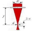
Figure 8. Focusing of the output laser beam
4. RESULTS AND DESCUSSION
The system was equipped with a computerized X-Y table, to control the movement of the workpiece. The movement velocity can be selected through the software parameters. The range of velocity available for this table is from 0.5 – 6 cm/sec in 0.5 cm/sec step.
From the large amount of different types of nonmetallic materials, four categories of these materials have been selected for this work [paper, plastic, glass and texture] currently used in various industrial applications.
The thickness of the selected materials varied from 0.11 to
1mm according to the material type as shown in table 2. The
cutting experiments carried out by the designed CO2 laser
with output power varies according to material type. The laser
beam is focused on the upper surface of the material. The ge- ometrical characteristics of the cuts were visualized and measured by means of an optical microscope.
TABLE 2
THICKNESS OF THE PROCESSED MATERIALS
A systematic study of the influence of the different varia- bles involved in the cutting process has been conducted in order to find the adequate window of parameters for satisfac- torily cut of the four categories of nonmetallic materials. Therefore each parameter was varied while keeping all others constant and the process has been repeated for materials of different thickness and with varying the speed and the output power for each kind of material. Paper, cardboard and other packaging materials which are thermally sensitive can be cut easily and quickly with the CO2 laser system.
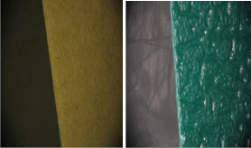
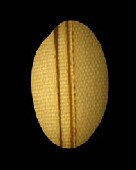
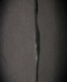
Figure 9(a) shows a clean, smooth and small kerf width of the processed paper sheets. The procedure parameters of 11W output power and 4cm/sec speed motion is the best module of the designed CO2 system for cutting 11 paper sheets with 50 μm kerf width. Figure 9(b) presents an image of cutting edge of polypropylene piece with 300 μm thickness. Results show that cutting 3 sheets of polypropylene with 13 W output pow- er and 4cm/sec are the optimum parameters to get the clean- est and the sharpest kerf width of 90 μm. The designed system is used to separate glass strips which is brittle and transparent with small thickness (1 mm). figure 9(c) illustrate the usage of laser output power of 20 W and speed of 4cm/sec results in smooth, small and fine kerf width of 120 μm. The low speed with high value of output power is the perfect conditions to cut the glass with almost no cracking where the glass surface is heated by laser beam. Compressive stress builds up in sur- face layers, but with no surface damage. Propagation of incip- ient crack in the glass sheet along the cut line leads to cutting and separation. Laser cutting equipment can be used to quick- ly and easily cut a broad range of textiles and clothing, from filter mats, canvas, fleece, and insulating materials to standard leather and cotton, even the thickest of materials such as Kev- lar can be cut with ease. The used textile piece is cotton with
170 μm thickness and it has 30% polyester, so this piece is very sensitive to temperature. The optimum conditions to obtain the cleanest cut with kerf width of 70 μm were; laser power of
12.5 W with very low speed of 2.5 cm/sec. The optimum pa- rameters are listed in table 3. as a guide for industries that use CO2 for cutting of non-metallic materials.
IJSER © 2015 http://www.ijser.org
International Journal of Scientific & Engineering Research, Volume 6, Issue 5, May-2015 1581
ISSN 2229-5518
TABLE 3
OPTIMUM LASER POW ER AND SPEED FOR CUTTING PAPER, PLAS- TIC, GLASS AND TEXTURE
MATERI- AL | THICKNESS OF SHEET (µM) | NUMBER OF SHEETS | SPEED (CM/SEC ) | POWER (W) |
PAPER | 110 | 11 | 4 | 11 |
PLASTIC | 300 | 3 | 4 | 13 |
GLASS | 1000 | 1 | 2 | 14.5 |
TEXTURE | 170 | 5 | 2 | 12.5 |
(a) (b)
(c) (d)
Figure 9. Images of cutting different nom-metallic materials with optimum condition of the designed CO2 laser. (a) Paper, (b) Polypropylene, (c) Glass, and (d) Textile.
4. CONCLUSION
The general idea is building a CO2 laser with appropriate character- istics of wavelength, power, coherent and monochromatic laser ra- diation, for the cutting of non-metallic materials according to indus- trial application, where it is possible combine high reliability and low operating cost. The work done is mainly application study of the performance of a CW CO2 laser system for cutting non-metallic materials. Plastic, paper, glass and texture exhibit high absorption at
10.6 μm and require moderate power level of 1-20 W. Thus, the con-
struction of axial flow, continuous wave carbon dioxide laser was
proposed for the current work. The experimental results show that the cutting quality varies with the kind of the materials and cutting speed. This system will allow carrying out different industrial appli- cations.
5. REFERENCES
[1] J. C. Polanyi. Selective excitation through vibrational energy transfer and optical maser action in N2-CO2. J. Chem. Phjs. 1961; 34, 347
[2] C. K. N. Patel. Continuous-wave laser action on vibrational–rotational tran- sitions of CO2. Phys. Rev. 1964; 136 (5A), A1187
[3] I. Kitazima. Effect of He and N2 on pulsed operation of CO2 lasers. Opt. Comm. 1974; 10 (2): 141-144
[4] Hall D R and Hill C A. Radiofrequency discharge excited CO2 lasers Hand- book of Molecular Laseres. New York: Marcel Dekker Inc.; 1987, p 165-257
[5] Witteman W J. The CO2 Laser. Berlin: Springer Verlag; 1987
[6] Ready J F. Industrial Applications of Lasers. New York: Academic
Press; 1978.
[7] www.laserk.com/newsletters/whiteCO.htm, David R. Whitehouse Manager, Laser Advanced Development Center Raytheon Co., Waltham, Mass.
[8] O’Shea Donald C., Callen Russell W., Rhodes William T. Introduction to Lasers and Their Applications. Reading, MA: Addison- Wesley Publish- ing Co.; 1977.
[9] J.Gary Eden. Selected Papers on Gas Laser Technology. Milestone Se- ries, SPIE , MS 159; 2000.
[10] Verdeyen J T. Laser Electronics. New Jersey: Prentice-Hall; 1981
[11] Levatter, Jeffrey, and Stong. The amateur scientist: a carbon dioxide laser is constructed by a high school student in california Scient. Amer.
1971; 225: 218-224.
[12] Weber M J. Handbook of Laser Science and Technology (Gas Lasers). Boca Raton:CRC Press; 1986.
[13] Seigman A E. Lasers. Mill Valley: University Science Books; 1986.
[14] G Botero, D Gomez, D Nisperuza, A Bastidas. Design and perfor- mance of a sealed CO2 laser for industrial applications. Journal of Physics: Conference Series 274,012058, IOP Publishing, doi:10.1088/1742-
6596/274/1/012058; 2011.
[15] N. Rykalin, A. Uglov, I. Zuev, A. Kokora. Laser and electron beam material processing. MIR Publishers, Moscow; 1988.
IJSER © 2015 http://www.ijser.org
International Journal of Scientific & Engineering Research, Volume 6, Issue 5, May-2015 1582
ISSN 2229-5518
IJSER © 2015 http://www.ijser.org