International Journal of Scientific & Engineering Research, Volume 6, Issue 4, April-2015 1279
ISSN 2229-5518
Design and Development of a Rectifier Stage
Topology for µgrid
M.Manigandan, Dr.B.Basavaraja and G.Srikanth
Abstract— Microgrids (µ-grids) are new way of electrical systems consisting of distributed energy sources and sensitive loads. The subjective of operation is to distribute stable and quality electric power. As it is intricate for the use of a real µ-grid for laboratory project, development of a model that can be connected and utilized for nominal loads. The design and development of a new system configuration of the front-end rectifier stage for µ-grid is presented in this paper. First, the mathematical model of µ-grid is developed and this configuration allows the µ-grid to supply the load separately or simultaneously depending on the availability of the energy sources. Proposed hardware implementation involves Cuk-SEPIC fused converter, a cascaded multilevel inverter and a variable load. The inherent nature of this Cuk-SEPIC fused converter, additional input filters are not necessary to filter out high frequency harmonics. For extraction of maximum power from the Solar PV and wind an adaptive MPPT is used specifically a standard perturb and observe method is used for Solar PV Hardware and Simulation results will given the scope for the use of proposed Rectifier Stage Topology.
Index Terms— Microgrid (µ-grid), Cuk converter, SEPIC converter, MLCI
—————————— ——————————
1 INTRODUCTION
he electrical grid is tending to be more distributed, intelli- gent, and flexible. The trend of this new grid is to become more and more distributed, and hence the energy genera-
tion and consumption areas cannot be conceived separately. Nowadays electrical and energy engineering have to face a new scenario in which small distributed power generators and dispersed energy storage devices have to be integrate together into the grid. A trend for the change in the performance of existing distributed generations from backup to immediate energy supply and to have a malleable contact approach which sets up for the concept of Microgrid have become incip- ient. Microgrids (µ-grids) have becoming an important con- cept to integrating distributed renewable sources and energy storage systems.
Managerial and technology, variation for power generation, environmental and economical enticements and the expansion of smaller generating systems like solar, wind, microturbine power generators have opened new goal for on-site power generation by electricity consumers [1-4]. Among all sources of µ-grid Solar PV and Wind energy holds the most potential to meet our demands. Specifically Wind energy has a high potential in supplying large amount of power but it depends on the velocity of wind at particular location. Similarly, Solar PV is also having high potential in severing load but it mostly serves potentially in the day light. By considering the draw- backs and their inherent natures a common maximum power point tracking (MPPT) algorithms is made for coupled source for improving the output power, power transfer efficiency and reliability significantly
When an individual input source is insufficient in convention the local load demands, the alternate energy source can satisfy for the change.
Many scholars have been suggested a simpler multi-input
structure by integrating renewable sources from the DC-end
with MPPT for each renewable source and many have pro-
posed a fusion of the buck and buck-boost converter and giv-
en a scope for further development [5-7]. With the literature
a passive input filters are required to remove passive input
remove the hike in current harmonics frequencies squeeze into generators of wind turbine [8-9]. The increase in power loss and decrease in lifespan of generators can be reduced by re- ducing harmonic content in generator.
In this paper, an alternative multi-input rectifier topology is proposed for µ-grid (hybrid Solar/Wind system). Hardware design is a blend of the Cuk and SEPIC converters [10-12]. The proposed topology will give a scope for the use of µ-grid with MPPT for individual source and rectification circuits. Hard- ware and Simulation results are lend to check with the utility of the proposed system.

Fig.1: Hybrid system with multi-connected boost converter
2 MICROGRID (µ-GRID)
2.1 Solar PV:
Photo Voltaic module basically in build with solar cell and it is the element in charge of transforming the sun rays or photons directly into power. For a Solar system, the voltage output is a constant DC whose magnitude depends on the composition in which the solar cells/ modules are connected [14]. The process of regulating the voltage and current output of the array must be upgraded based on the weather conditions such as irradia- tion.
Figure 2 & 3 represents the simulation results of solar with and without MPPT and I-V and P-V characteristics using
IJSER © 2015 http://www.ijser.org
International Journal of Scientific & Engineering Research, Volume 6, Issue 4, April-2015 1280
ISSN 2229-5518
Guide. Maximum power point tracking (MPPT) algorithm is developed to constantly extract the maximum amount of power from the array under varying conditions. The Ideal equations determining the I-V characteristics of the PV cell is.
 (1)
(1)
Where 
 (2)
(2)

Where, Iil is the current generated by the sun irradiation, Idiode is the diode equation, ILCdiode cell is the leakage current of the diode.
Fig.2: Simulation Output of Solar with and without MPPT

Electron charge q = 1.60217646*10-19 C, k is the Boltzmann constant and T is the temperature, and 'ad ' is the diode ideally constant.
Ar : Rotor area in (square meter)
Vw : Wind velocity without rotor interference,

Fig.4: Simulation Output of Wind
3 PROPOSED RECIFIER STAGE TOPOLOGY
The Power electronics research community and in- dustry have reacted to this demand in two different ways: developing semiconductor technology to reach higher nomi- nal voltages and currents. A system diagram of the proposed recti- fier stage of a hybrid energy system is shown in Figure 5, The fusion of the two converters is achieved by reconfiguring the two existing diodes from each converter and the shared utilization of the Cuk output inductor by the SEPIC converter. This configuration allows each converter to operate normally individually in the event that one source is unavailable. Figure5 illustrates the case when only the wind source is available. In this case, D1 turns off and D2 turns on; the proposed circuit becomes a SEPIC converter and the input to output voltage relationship is given by (4). On the other hand, if only the PV source is available, then D2 turns off and D1 will always be on and the circuit becomes a Cuk converter as shown in Figure 6.The input to output voltage relationship is given by (5). In both cases, both converters have step-up/down capability, which provide more design flexibility in the system if duty ratio control is utilized to perform MPPT control.
 (4)
(4)

(5)
2.2 Wind:
Fig.3: I-V, P-V characteristics using Guide
The mathematical expression that relates the total output voltage and the two input sources are been illustrated
To find an expression for the output DC bus voltage,
he main components of a wind energy conversion system, in-
cluding turbine blade, a gearbox, Converters, Inverters, Control circuits etc along with cables, filters, ground support equipment and interconnection equipment [13,15]. Wind turbine captures power from wind by means of turbine blades and converts it into mechanical power and Fig.2 represents the simulation output of Wind. The power contained in the wind is given by the kinetic energy of the flowing air mass per unit time as follows
Vdc , the volt-balance of the output inductor, according to Fig- ure 8. It is observed that Vdc is simply the sum of the two out- put voltages of the Cuk and SEPIC converter. This further im- plies that Vdc can be controlled by d1 and d2 individually or simultaneously
= (3)

Where Pw : Power contained in wind (in watts),
ρ : Air density,
IJSER © 2015 http://www.ijser.org
Table1:Modes of switching states
International Journal of Scientific & Engineering Research, Volume 6, Issue 4, April-2015 1281
ISSN 2229-5518


respective duty cycle (d1)


Figure 5: Proposed rectifier stage for a Hybrid wind/PV system

(6) (7)
Therefore by adjusting the respective duty cycles for each energy source, maximum power point tracking can be achieved.
(8)
(9)


Figure 6: Only wind source is opera- tional (SEPIC)

As for the current stress, it is observed from Figure 8 which is
the peak current always occurs at the end of the on-time of the 
MOSFET.
Proposed Circuit inductor Waveforms
Fig8.

Figure 7: Only PV source is operation (Cuk)

4 MPPT CONTROL OF PROPOSED CIRCUIT
(10)
The PV output current, which is also equal to the average in- put current of the Cuk converter, is given in (10). It can be ob- served that the average inductor current is a function of its
A common inherent drawback of wind and PV systems is the intermittent nature of their energy sources.
The power coefficient (Cp) is a nonlinear function that rep- resents the efficiency of the wind turbine to convert wind energy into mechanical energy. It is dependent on two variables, the tip speed ratio (TSR) and the pitch angle. The TSR, λ, refers to a ratio of the turbine angular speed over the wind speed.
Radius of turbine blade (r) Wind velocity (Vw )
Blade Pitch angle (β) Angular velocity (ωr )
Blade tip speed (λ)  ) Turbine Power Coefficient (Cp ) Maximum value of Cp is 59.3% ≈ 0.59
IJSER © 2015 http://www.ijser.org
International Journal of Scientific & Engineering Research, Volume 6, Issue 4, April-2015 1282
ISSN 2229-5518


x = different for various turbine design
,c1=0.5176,c2,116,c3=0.4,c4=5,c5=21,c6=0.0068

Power Coefficient Curve for a typical wind turbine

Figure 9: Power Curves for a typical wind turbine
Figure 8:
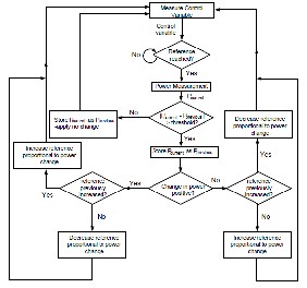
Figure 10: General MPPT Flow Chart for wind and PV
5 CASCADED MULTILEVEL INVERTER
The Cascade multilevel inverter subsists of a series of the H- bridge inverter units. The number of output phase voltage levels is 2S+1, where S is the number of DC sources and ‘s’ is the num- ber of H-bridges connected in cascade per phase. Among ‘s’ number of switching angles, generally one switching angle is used for fundamental voltage selection and the remaining (s-1) switching angles are used to eliminate certain predominating lower order harmonics. In a three-phase system with isolated neutral, triplen harmonics are cancelled out automatically, and only non-triplen odd harmonics are present [17]. The fundamen- tal voltage is obtained from the calculated switching angles α1 , α2 , α3 … αn and ‘n’ represents the order of the harmonics and the switching angles are identical to the number of DC-sources. It is required to find the switching angles in the range of 0 to π/2 con- sidering 3rd, 5th and 7th order phase voltage to zero.
The sum of all of the individual inverter outputs (V1 +V2 +V3 =Vout ) is represented in Figure.5,is voltage waveform of series H-bridge inverter which are proficient by connecting the
Hill climb search (HCS) a maximum power point tracking scheme allowed for shaping Solar and wind curves which is often applied to these energy sources to extract maximum power [16]. Conversely, if a negative change in the output power is observed, then the control algorithm will reverse the direction of the pervious perturbation step. In the case that the change in power is close to zero then the algorithm will invoke no changes to the system operat- ing point since it corresponds to the maximum power point.The MPPT scheme employed in this paper is a version of the HCS strate- gy. Figure 10 is the flow chart that illustrates the implemented MPPT scheme.
In conventional multilevel inverters, the power semi- conductor switches are combined to produce a high frequency waveform in positive and negative polarities. However, there is no need to utilize all the switches for generating bipolar lev- els.
DC source to AC output by using multiple combinations of switches.
The Fourier series of the quarter-wave symmetric for the above staircase waveform is written as follows:  (11)
(11)
For seven level cascade inverter the fundamental voltage in terms of switching angles is given in equation (12).  (12)
(12)
When all the switching angles are zero

Maximum fundamental voltage ( Modulation index (M) (13)
IJSER © 2015 http://www.ijser.org
International Journal of Scientific & Engineering Research, Volume 6, Issue 4, April-2015 1283
ISSN 2229-5518

The 7-level cascaded inverter requires three H-bridges. The non linear equations which are used to finding the switching angles and desired fundamental voltage of 7-level inverter are equations (17), (18), (19) and (20).
Fig.11: Schematic diagram of H-bridge series-connected multilevel in- verter.

6 HARDWARE AND SIMULATION RESULTS
(17) (18) (19) (20)

Fig.12: Switching angles of H-bridge series-connected multilevel invert- er.
The general function of the cascade multilevel inverter is to incorporate a desired voltage from several separate DC sources as shown in Fig.4. Each DC Source is connected to an H-bridge inverter and can generate three different voltage outputs, +Vdc, 0 and –Vdc [18]. The sum of all of the individual inverter outputs (V1 +V2 +V3 =Vout ) are represented in Figure.5,is voltage wave- form of series H-bridge inverter which are proficient by connect- ing the DC source to AC output by using multiple combinations of switches. Cascade multilevel inverter generally incorporated with different voltage sources and in these proposed cascade mul- tilevel inverter DC sources as shown in figure 6 are replaced by
µgrid (Solar, wind and Fuel Cell)
The Fourier series of the quarter-wave symmetric for the above staircase waveform is written as follows:


Fig.13: Design of Hardware Rectifier Stage Topology with 3-levelinverter
Fig.14
: Design of Hardware Rectifier Stage Topology with 5-levelinverter
Table 2: Switching Values of different Iterations using NR Method
 (14)
(14)
For seven level cascade inverter the fundamental voltage in

terms of switching angles is given in equation (15).
When all the switching angles are zero

Maximum fundamental voltage (
(15)

Modulation index (M) (16)
IJSER © 2015 http://www.ijser.org
International Journal of Scientific & Engineering Research, Volume 6, Issue 4, April-2015 1284
ISSN 2229-5518

Fig.15: Graphical representation of different Switching Values

Fig.16: Output Waveform of three level cascaded Inverter

Fig 17: Output Waveform of five level Inverter
7 CONCLUSION
Now-a-days, The Microgrid is aggregations of resources are- connected to the different application as DC source. In this paper, an alternative multi-input rectifier topology is pro- posed for µ-grid (hybrid Solar/Wind system). Hardware de-
————————————————
• M.Manigandan is currently working as Assistant Professor in Department of EEE at GITAM University, Hyderabad. E-mail:manimatlab@gmail.com
• Dr.B.Basavaraja is currently working as Professor & Chairman at Univer- sity BDT College of Engineering.E-mail: banakara36@gmail.com
• G.Srikanth currently pursuing Masters in Power systems and Automation at GITAM University Hyderbad .Email:srikanthg345@gmail.com
sign is a blend of the Cuk and SEPIC converters. The proposed topology will give a scope for the use of µ-grid with MPPT for individual source and rectification circuits. Hardware and Simulation results are lend to check with the utility of the pro- posed system
REFERENCES
[1] Y. Ito, Z. Yang, and H. Akagi, “DC Microgrid Based Distribution Power Generation System,” in Proc. IEEE Int. Power Electron. Motion Control Conf., vol. 3, pp. 1740-1745, Aug. 2004
[2] P. Chiredeja and R. Ramakumar, “An approach to quantify the technical benefits of distributed generation,” IEEE Trans. Energy Conversation, vol.19, no. 4, pp. 746-773, Dec. 2004.
[3] T.E. McDermott and R.C. Dugan, “Distributed Generation Impact on Reliability and Power Quality” in Proc. of IEEE Conf. on Rural Electric Power,2002, pp. D3-D3_7.
[4] S.K. Kim, J.H Jeon, C.H. Cho, J.B. Ahn, and S.H. Kwon, “Dynamic Modelling and Control of a Grid-Connected Hybrid Generation System with Versatile Power Transfer,” IEEE Transactions on IndustrialElectronics, vol.
55, pp. 1677-1688, April 2008.
[5] Arulampalam, N. Mithulananthan, R.C. Bansal, and T.K. Saba, “Micro grid Control of PV -Wind-Diesel Hybrid System with Islanded and Grid Connected Operations,” in Proc. IEEE Int. Conf. Sustainable Energy Technologies, pp. 1-5, 2010
[6] N. A. Ahmed, M. Miyatake, and A. K. Al-Othman, “Power fluctuations suppression of stand-alone hybrid generation combining solar photovoltaic/wind turbine and fuel cell systems,” in Proc. Of EnergyConversion and Management, Vol. 49, pp. 2711-2719, October 2008
[7] S. Jain, and V. Agarwal, “An Integrated Hybrid Power Supply for Distributed Generation Applications Fed by Nonconventional Energy Sources,” IEEE Transactions on Energy Conversion, vol. 23, June2008
[8] S.L. Helter et.al, “photovoltaic module and array evaluation,”IEEE 1984,pp
700-704.
[9] T.Ackermann, wind power in power systems, wileyNew York, 2005.
[10] R. W. Erickson, “Some Topologies of High Quality Rectifiers” in theProc. of the First International Conference on Energy, Power, and Motion Control, May 1997.
[11] D. S. L. Simonetti, J. Sebasti´an, and J. Uceda, “The DiscontinuousConduction Mode Sepic and ´ Cuk Power Factor Preregulators: Analysis and Design” IEEE Trans. On Industrial Electronics, vol. 44,no. 5,
1997
[12] N. Mohan, T. Undeland, and W Robbins, “Power Electronics: Converters, Applications, and Design,” John Wiley & Sons, Inc., 2003.
[13] J. Marques, H. Pinheiro, H. Grundling, J. Pinheiro, and H. Hey, “A Survey on Variable-Speed Wind Turbine System,” Proceedings of Brazilian Conference of Electronics of Power, vol. 1, pp. 732-738,2003.
[14] F. Lassier and T. G. Ang, “Photovoltaic Engineering Handbook” 1990
[15] Global Wind Energy Council (GWEC), “Global wind 2008report,”June 2009. [16] L. Pang, H. Wang, Y. Li, J. Wang, and Z. Wang, “Analysis of Photovoltaic
Charging System Based on MPPT,” Proceedings of Pacific-Asia Workshop
on Computational Intelligence and Industrial Application 2008 (PACIIA
‘08), Dec 2008, pp. 498-501.
[17] John N. Chiasson, Leon M. Tolbert, “Elimination of Harmonics In Multilevel Inverters Using the theory of Symmetric polynomial and Resultant” Proceedings of the 42nd IEEE Conference on Decision and Control Maui, Hawaii USA, December 2003.
[18] Zhong Du, Leon M. Tolbert, John N. Chiasson “Reduced Switching Frequency Computed PWM method for multilevel converter control” Power Electronics Specialists Conference, 2005. PESC ’05. IEEE, 2005, Page(s):
2560 – 2564.
IJSER © 2015 http://www.ijser.org