
International Journal of Scientific & Engineering Research Volume 2, Issue 8, Auguest-2011 1
ISSN 2229-5518
Design and Analysis of single disc machine top and bottom cover
S.Varatharajan, R.Krishnaraj, Dr.M.Sakthivel, K.Kanthavel, Deepan Marudachalam M.G, R.Palani
)
Abstract— The use of structural calculation software based on finite element analysis is nowadays a common practice when designing new industrial products processed from thermoplastic materials like polyamides or ABS. in order to make an adequate Prediction of the service behavior of the plastics component, it is Essential to carry out appropriate analysis when working with the software. This requires both the correct mechanical characterization of the materials used for inputting the required properties in the calculation code, and the specification of the different solution characteristics. In this work, two materials (polyamide and ABS) have been studied for the analysis of single disc machine. The single disc machine includes top cover and bottom cover. Where the top cover consist of motor, pulley and the provision provided for inserting the handle of the machine. The analysis of the top cover is to increase the contact force between the brush and surface. for that a mass of 12kg is Placed on the space provide for the top cover and The structural analysis should be carried out i n the top cover in order to reduce the maximum stress and deformation level within the safe limit. Whereas The linear impact analysis is carried out on the bottom cover in order to find a good stiffness level and the minimum hand force at an angle of 60 degree is required for the machine avoid to hitting the wall. for that to make a slot on the bottom cover and place a rubber bush in the slot to reduce the deformation level as well as life time of the machine will also increased. This simulation tests are conducted in the finite element code ANSYS and stress deformation is calculated to achieve the efficient material.
Index Terms— Single Disc machine Top and Bottom cover, FEA analysis
—————————— ——————————
plastic is an organic polymer, available in some resin form or some form derived from the basic po- lymerized resin. These forms can be liquid or paste
like resins for embedding, coating, and adhesive bonding, or they can be molded, laminated, or formed shapes, in- cluding sheet, film, or larger-mass bulk shapes The num- ber of basic plastic materials is large, and the list is in- creasing. In addition, the number of variations and mod- ifications to these plastic materials is also quite large. The methods by which these materials are processed, finished, and prepared for final use is also immense. Together, the resultant quantity of materials and processes available is just too large to be completely understood and correctly applied by anyone other than those whose day-to- day work puts them in direct contact with a diverse selection of materials. Although there are numerous minor classifi- cation schemes for polymers, depending on how one wishes to categorize them, nearly all polymers can be placed in one of two major classifications— thermosetting materials (or thermo sets) and thermoplastic materials. Likewise, foams, adhesives, embedding resins, elastomers
, and so on, can be subdivided into thermoplastic and thermosetting classifications.
John R. Edwards, San Jose, CA [1], they examined that a study of the shock response of a hard disk drive dropped from a height on to a surface with a specific contact stiffness is presented. They explained a finite element model of the hard disk drive was developed and transient response analysis of the model was performed to evaluate the shock problem. The study shows why a disk drive is particularly sensitive to shock inputs with narrow pulse widths in the order of 0.5 to 1 millisecond and presents the results of simulating the shock response of an entire
HDD dropped onto surfaces with different contact stiffness values. The simulations demonstrate the effect the surface stiffness characteristics have on both the magnitude and the pulse width of the impact shock received by the HDD and the dramatic changes in the responses of the internal components of the HDD to these different shocks.
M.Iizukal, Y.Kanai, T.Abe, M.Sengoku, and K.Mukasa [3] they examined that the design improvements of the met- al-in-gap head for rigid disk files using a finite-element method (FEM) which takes into account magnetic satura- tion will be discussed. The saturation flux density of the alloy film, thickness of the alloy film and throat height of the metal-in-gap head are all calculated analytically in Order to yield a more intensive and sharper field. It has been found that when the MIG head is manufactured as a trial and measurement of the write field is evaluated, the following data is obtained. They finding out the im- proved MIG head will advance high-density recording for rigid disk files.
Michal Kristofic, Anna Ujhelyiova [4],they examined that the synthesis of co polyamides consisting of e- caprolactam and 5.9-19.7 wt.% of nylon salt ADETA, pre- pared from adipic acid + die thyle ne triamine and the physical & thermal properties of polyamide 6 and co- polyamides, are reported. The content of this low molecu- lar compound is comparable with that reported for crude polyamide 6. The molecular weight of each co-polyamide is lower. The melting temperature is lower in comparison with PAG, and corresponds to that of the nylon salt ADETA. The crystallisation ability of co-polyamides is higher, and secondary crystallisation mainly contributes to the higher degree of crystalline. The state of organisa-
IJSER © 2011
International Journal of Scientific & Engineering Research Volume 2, Issue 8, Auguest-2011 2
ISSN 2229-5518
tion in co-polyamide s, on the basis of As values, seems to be better, mainly for the samples with developed crystal- lisation (i.e. after a long period of crystallisation).They finding out some properties of polymer products (such as mechanical properties) depend on the molecular weight of the polymer and additives used. A lower molecular weight negatively influences the mechanical properties mainly in oriented products such as fibres, films etc. For this reason, evaluation of the molecular weight (or other dependent characteristic) of the component of the blend is important. The amount of low molecular (hot water- soluble) compounds (LMC) is also important from the point of view of the efficiency of the polymer blend's pro- duction (and the recycling of the reaction components). Kasama Jarukumjorn, Nitinat Suppakarn, Wittawat wongsorat [5], suggested the addition of 20 per filler to the rubber matrix increased maximum torque as well as properties such as modulus and hardness compared to the unfilled compound. Scorch time and cure were not much affected by filler types. A good reinforcement effect on the NR with NaOH treated sisal fiber was probably due to the better rubber-filler interaction
Sandhya Rani, Kanchan Bag [6] they examined that the validation of dumper body design through finite element method (FEM). The preliminary design was carried out as per the telecom standards and modelling was done using standard CAD tools. For finite element analysis (FEA), meshing was performed using hyper mesh, linear static analysis was carried out for various load cases and all stress results are found within safe limit. However slight modifications in design were done to reduce cost and weight without compromising functional requirement. Linear static analysis was performed with the same load case in order to find out the reliability of the body and to investigate mechanical failures. Drop impact test analysis was performed. The scope of this paper is limited to li- near static analysis and impact drop test of dumper body using the capability of radios using hyper mesh, opti- struct and radios, linear static analysis has been carried out successfully stress levels obtained in analysis are within the accepted limits
A semi-crystalline, white engineering thermoplastic very similar to nylon 6 with which it is in many respects inter- changeable. Its melt viscosity is not quite as low as 6 so it is generally slightly easier to process and often preferred for molding. Relative to 6 it has somewhat higher impact strength but somewhat lower strength and stiffness and higher water absorption (the highest of all nylons).It can be monomer cast, commonly called just cast - ie.polymerised in a mould direct to a semi-fabricated shape. This allows the production of thick sections with- out voiding and gives a product with a slightly different balance of properties - a little stronger and stiffer, slightly reduced extensibility and impact strength
Nylon was the first commercially successful poly- mer and the first synthetic fiber to be made entirely from coal, water, and air. These are formed into monomers of
intermediate molecular weight, which are then reacted to form long polymer chains. Nylon was intended to be a synthetic replacement for silk and substituted for it in many different products after silk became scarce during World War II. It replaced silk in military applications such as parachutes and flak vests, and was used in many types of vehicle tires. Nylon fibers are used in many ap- plications, including fabrics, bridal veils, and carpets, musical strings, and rope. Solid nylon is used for mechan- ical parts such as machine screws, gears and other low- to medium-stress components previously cast in metal. En- gineering-grade nylon is processed by extrusion, casting, and injection molding. Solid nylon is used in hair combs. Type 6/6 Nylon 101 is the most common commercial grade of nylon, and Nylon 6 is the most common com- mercial grade of molded nylon. Nylon is available in glass-filled variants which increase structural and impact strength and rigidity, and molybdenum sulfide-filled va- riants which. Above their melting temperatures, Tm, thermoplastics like nylon are amorphous solids or viscous fluids in which the chains approximate random coils. Be- low Tm, amorphous regions alternate with regions which are lamellar crystals. The amorphous regions contribute elasticity and the crystalline regions contribute strength and rigidity. The planar amide (-CO-NH-) groups are very polar, so nylon forms multiple hydrogen bonds among adjacent strands. Because the nylon backbone is so regular and symmetrical, especially if all the amide bonds are in the Trans configuration, nylons often have high crystalline and make excellent fibers. The amount of crys- talline depends on the details of formation, as well as on the kind of nylon. Apparently it can never be quenched from a melt as a completely amorphous solid. Nylon 6,6 can have multiple parallel strands aligned with their neighboring peptide bonds at coordinated separations of exactly 6 and 4 carbons for considerable lengths, so the carbonyl oxygen's and amide hydrogen's can line up to form inter chain hydrogen bonds repeatedly, without interruption. Nylon 5,10 can have coordinated runs of 5 and 8 carbons. Thus parallel (but not anti parallel ) strands can participate in
Nylons are condensation copolymers formed by reacting equal parts of a diamond and a di carboxylic acid, so that peptide bonds form at both ends of each monomer in a process analogous to polypeptide biopolymers. Chemical elements included are carbon, hydrogen, nitrogen, and oxygen. The numerical suffix specifies the numbers of carbons donated by the monomers; the diamond first and the di acid second. The most common variant is nylon 6-6 which refers to the fact that the demine (hex ethylene de- mine) and the diacid (adipic acid) each donate 6 carbons to the polymer chain. As with other regular copolymers like polyesters and polyurethanes, the "repeating unit" consists of one of each monomer, so that they alternate in the chain. Since each monomer in this copolymer has the
IJSER © 2011
International Journal of Scientific & Engineering Research Volume 2, Issue 8, Auguest-2011 3
ISSN 2229-5518
same reactive group on both ends, the direction of the amide bond reverses between each monomer, unlike nat- ural polyamide proteins which have overall directionali- ty: C terminal —» N terminal. In the laboratory, nylon 6 can also be made using adipoyl chloride instead of adipic it is difficult to get the proportions exactly correct, and deviations can lead to chain termination at molecular weights less than a desirable 10,000 daltons (u). To over- come this problem, a crystalline, solid "nylon salt" can be formed at room temperature, using an exact 1:1 ratio of the acid and the base to neutralize each other. Heated to
285 °C, the salt reacts to form nylon polymer. Above
20,000 daltons, it is impossible to spin the chains into
yarn, so to combat this, some acetic acid is added to react
with a free amine end group during polymer elongation to limit the molecular weight .In practice and especially
for 6 the monomers are often combined in a water solu- tion. The water used to make the solution is evaporated under controlled conditions, and the increasing concen- tration of "salt" is polymerized to the final molecular weight.
Nylon can be used as the matrix material in composite materials, with reinforcing fibres like glass or carbon fi- ber, and has a higher density than pure nylon. Such thermoplastic composites (25% glass fibre) are frequently used in car components next to the engine, such as ex- haust manifolds, where the good heat resistance of such materials makes them feasible competitors to metals
Depending on the change of strain rate versus stress in-
side a material the viscosity can be categorized as having
a linear, non-linear, or plastic response. When a material
exhibits a linear response it is categorized
A visco elastic material has the following properties:
Hysteresis is seen in the stress-strain curve.
Stress relaxation occurs: step constant strain causes decreasing stress
Creep occurs: step constant stress causes increas-
ing strain
Variation of luster: nylon has the ability to be very lustrous, semi lustrous or dull.
Durability: its high tenacity fibers are used for seatbelts, tire cords, ballistic cloth and other uses.
High elongation
Excellent abrasion resistance
Highly resilient (nylon fabrics are heat-set)
Paved the way for easy-care garments
High resistance to:
o insects, fungi and animals o
o molds, mildew, rot
o many chemicals
Used in carpets and nylon stockings
Melts instead of burning
Used in many military applications
It must be made clear that polymers respond to applied loads very differently to metals, making direct compari- sons of strength and stiffness of limited use. For example, a large number of design formulae have been derived for beams, plates and columns dependent on the elastic modulus as a fundamental measure of the response of the material to stress, the implicit assumption being that the material behaves in a linear, elastic manner until yielding. For most metals, this is true; for polymers, the stress- strain curve is rarely linear, there is no true proportional limit and the behaviors are greatly affected by strain rate and temperature. Because a polymer behaves in a manner that seems to combine elastic solid and highly viscous behaviors, they are termed Viscoelastic1.
Fig1. Stress - strain curve: viscoelastic creep
Visco elastic materials creep under steady stress and relax
under steady strain. In order to design a: component that
will not creep more than, say, 1% over its projected life
IJSER © 2011
International Journal of Scientific & Engineering Research Volume 2, Issue 8, Auguest-2011 4
ISSN 2229-5518
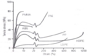
Fig2. Stress strain curve of various materials
time, it will be necessary to examine creep curves from
the material supplier to ascertain the stress level that will
restrict creep to this limit.
Acrylonitrile butadiene styrene (ABS) (chemical formula (CsHs- C4H6-C3H3N)n) is a common thermoplastic used to make light, rigid, molded products such as piping (for example Plastic Pressure Pipe Systems), musical instru- ments (most notably recorders and plastic clarinets), golf club heads (used for its good shock absorbance), automo- tive body parts, wheel covers, enclosures, protective head gear, buffer edging for furniture and joinery panels, air- soft BBs and toys, including Lego bricks. ABS plastic ground down to an average diameter of less than 1 micrometer is used as the colorant in some tattoo inks. Tattoo inks that use ABS are extremely vivid. This vivid- ness is the most obvious indicator that the ink contains ABS, as tattoo inks rarely list their ingredients
It is a copolymer made by polymerizing styrene and acry- lonitrile in the presence of polybutadiene. The propor- tions can vary from 15 to 35% acrylonitrile, 5 to 30% bu- tadiene and 40 to 60% styrene. The result is a long chain of polybutadiene criss-crossed with shorter chains of poly (styrene-co-acrylonitrile). The nitrite groups from neigh- boring chains, being polar, attract each other and bind the chains together,
making ABS stronger than pure polystyrene. The styrene gives the plastic a shiny, impervious surface. The buta- diene, a rubbery substance, provides resilience even at low temperatures. ABS can be used between -25 and 60
°C. The properties are created by rubber toughening, where fine particles of elastomeric are distributed throughout the rigid matrix. Production of 1 kg of ABS requires the equivalent of about 2 kg of oil for raw mate- rials and energy. It can also be recycled
Table 1
Chemical Properties of ABS
Acids - concentrated | Poor |
Acids - dilute | Poor |
Alcohols | Good |
Alkalis | Good-Fair |
Aromatic hydrocarbons | Good |
Greases and Oils | Good |
Halogenated Hydrocarbons | Good-Fair |
Halogens | Poor |
Ketones | Good |
Acids - concentrated | Poor |
Acids - dilute | Poor |
Alcohols | Good |
Alkalis | Good-Fair |
Aromatic hydrocarbons | Good |
Greases and Oils | Good |
Halogenated Hydrocarbons | Good-Fair |
Halogens | Poor |
Ketones | Good |
from propylene and ammonia; butadiene is a petroleum hydrocarbon obtained from the C4 fraction of steam cracking; styrene monomer is made by dehydrogenation of ethy1 benzene- a hydrocarbon obtained in the reaction of ethylene and benzene. The advantage of ABS is that this material combines the strength and rigidity of the acrylonitrile and styrene polymers with the toughness of the polybutadiene rubber. The most important mechani- cal properties of ABS are resistance and toughness. A va- riety of modifications can be made to improve impact resistance, toughness, and heat resistance. The impact resistance can be amplified Even though ABS plastics are used largely for mechanical purposes, they also have good electrical properties that are fairly constant over a wide range of frequencies. These properties are little af- fected by temperature and atmospheric humidity in the acceptable operating range of temperatures w The final properties will be influenced to some extent by the condi- tions under which the material is processed to the final product; for example, molding at a high temperature im- proves the gloss and heat resistance of the product whe- reas the highest impact resistance and strength are ob- tained by molding at low temperature.
ABS polymers are resistant to aqueous acids, alkalis, con- centrated hydrochloric and phosphoric acids, alcohols and animal, vegetable and mineral oils, but they are swol- len by glacial acetic acid, carbon tetrachloride and aro- matic hydrocarbons and are attacked by concentrated sulfuric and nitric acids. They are soluble in esters, ke- tones and ethylene dichloride.
The aging characteristics of the polymers are largely in-
fluenced by the polybutadiene content, and it is normal to
include antioxidants in the composition. On the other
hand, while the cost of producing ABS is roughly twice
IJSER © 2011
International Journal of Scientific & Engineering Research Volume 2, Issue 8, Auguest-2011 5
ISSN 2229-5518
the cost of prarfwhff polystyrene, ABS is considered su- perior for its hardness, gloss, toughness, and electrical insulation properties. However, it will be degraded (dis- solve)5 When exposed to acetone. ABS is flammable when it is exposed to high temperatures, such as a wood fire. It will "boil", then burst spectacularly into intense, hot flames.
ABS is suitable for the conveyance of potable water, slur- ries and chemicals. Being non toxic ABS complies with the toxicological requirements of the British Plastics Fed- eration and the British Industrial Biological Research As- sociation (BIBRA) code of practice for food usage. ABS Pipe Systems are very suitable for chilled water applica- tions, due to its low temperature properties. ABS is also suitable for use in compressed airline systems.
Good chemical resistance
Good abrasion resistance
Good material strength and high impact resistance
Operating temperature range -40° C to +80° C Table 2
Mechanical properties of ABS
PROPERTIES | ABS |
Young's Modulus (GPa) | 2.00 |
Poisson Ratio (No unit ) | 0.4155 |
Density (Kg/mm3) | 1.12x10⁻⁶ |
Tensile yield strength (MPa) | 35 |
Compressive yield strength (MPa) | 68 |

Fig.3 Model of top and bottom cover
A finite element model of a small form factor model was created using the commercially available finite ele- ment software package, ANSYS version 8.1. The overall model includes the model enclosure base, the head stack assembly (HSA), which includes the over mold with inla-
id coil and two arms with two head suspension assem- blies, the pivot bearing and the disk. The details of the head gimbals assembly are also modeled. The over mold, pivot shaft, screw, shim, arm, slider are meshed with sol- id elements while the hinge, load beam, gimbals, disk and the enclosure base are meshed with shell elements. The pivot bearing is simulated with 36 spring elements. The shaft, screw, shim, gimbals, arm and suspension, enclose base are made of stainless steel with the density, Young’s modulus, Poisson’s Ratio being 8.08e-6 kg/mm³, 190 Gpa, and 0.32 respectively. Fig. 3 shows a view of the model before preloading. The Cartesian coordinate, X, Y, Z are parallel to the directions of the drive length, width, and thickness respectively. The whole FE model includes
10117 solid elements and 12722 shell elements. The sus-
pension is formed with an initial bending angle to pro- duce prescribed preloading force of 0.012 N. A displace- ment loading is applied to the four corner of the slider. The displacement loading pulls the suspensions to the proper z-height and lets the two sliders rest on the upper and lower surface of the disk respectively. This preload- ing process is simulated with an implicit nonlinear static analysis in ANSYS. After the implicit static analysis, the implicit FE model is converted to an explicit FE model. Before the explicit transient analysis, the locations of the nodes of the whole model are updated with the static analysis results and the preloading stress is retained in the FE model. ‘Automatic surface to surface contact’ is defined between the bottoms of the two sliders with the disk. Fig. 4 shows the three Z-negative shock pulses ap- plied in the drop test simulations. Shock pulse 1, 2 and 3 represent the acceleration of the -300 g (1 g=9.8 m/s 2 ) and 1 ms half sine shock pulse, -300 g and 0.5 ms half sine shock pulse and -600 g and 1 ms half sine shock pulse, respectively. The shock pulse is applied on the two short edges of the base in the simulation of the linear drop test as Fig. 5 shows. This is to simulate the up-side-down drop test condition-the two short base edges of model are clamped onto the drop table. The drop table drops from a range of different heights onto a surface with different stiffness.
IJSER © 2011
International Journal of Scientific & Engineering Research Volu
ISSN 2229-5518
Table 3![]()
Comparison of polyamide and ABS
PROPERTIES | POLYA- | ABS |
Young's Modulus | 1.725 , | 2.00 |
Poisson Ratio (No | 0.39 | 0.4155 |
Density | 1.12x10⁻⁶ | 1.12x10⁻⁶ |
Tensile yield | 52 | 35 |
Compressive | 105 | 68 |

FIG.4 STRESSES ON TOP COVER

FIG.5 STRESSES ON BOTTOM COVER
1. Gerald G.Trantina and Joseph T woods, 2003, “Standard test procedure for relevant material properties for structural analy- sis,” Journal of reinforced plastics and Composites, Vol. 10, No.13 Jan/2000, pp. 233-240.
2. Timothy A. Palmer, 2000, “10 common pitfalls in thin-wall plastic part design,” Journal of reinforced plastics and Compo- sites, Vol. 20, No.11 Dec/1999, pp. 127-141.
3. Sally Carter, and David Kazmer, 2001, “Studies of plastic boss design and methodology,” International journal of solid and structure, Vol. 10, No. April/2005, pp. 530-535.
4. Christopher Roster and David Kazmer, “Defect cost analysis,”
Journal of reinforced plastics and Composites, Vol. 22, No.1
Jan/2003, pp. 62-72.
5. Lellep.J and Puman.E, 2000, “Optimization of plastic conical
shell loaded by a rigid central boss,” International journal of
solid and structure, Vol. 37, No. June/2000, pp. 2695-2708.
6. Kurt,beiter,james.A cardinal’s and kotuku, 1997, “Preliminary plastic part design : focus on material selection and basic geo- metry while balancing mechanical performance and manufac- turing cost,” Journal of reinforced plastics and Composites, Vol. 16, No.14 Dec/1997, pp. 1293-1302.
7. Azhar Iqbal and John S.Hansen, 2006, “Cost - based, inte- grated design optimization,” Springer, Vol. 32, No. Septem- ber/2006, pp. 447-461.
IJSER © 2011
