The research paper published by IJSER journal is about Design Approach of Improved Response DC Motor Analyzing Motor Characteristics in terms of Electrical and Mechanical Constants with Control Engineering Parameters 1
ISSN 2229-5518
Design Approach of Improved Response DC Motor Analyzing Motor Characteristics in terms of Electrical and Mechanical Constants with Control Engineering Parameters
P M Ilius, M Z Heider, P M Rakibul
Abstract—Accuracy of adjustment of different parameters of DC motor makes the motor speed very smooth and steady, is the main prerequisite for designing a perfect DC motor so that it can be used for very precise rotation. So, the main aim of this paper is to provide a good guidance for some design considerations how to improve the response of DC motor minimizing its overshoot (%OS), rise time (tr), settling time (ts), steady state time (tss) and increasing the steady state speed until unity supplying step input to the mo tor. To observe the performance of the motor, equation of the transfer function has been derived setting all initial conditions to zero. Two machine constant coefficients (Motor torque constant (Kt) and back EMF constant (Ke)) have been investigated to derive the compact form relate d to the motor size and material property. The material property relates the electrical constants, armature resistance (Ra) and armature indu ctance (La). A mathematical approach, based on electromagnetic field theory, has been used to formulate the two machine constants. The system has been simulated using MATLAB to analyze the different parameters of DC motor that how the speed of the motor is improved s o that the range of parameter’s value can be specified.
Key Words: - DC Motor, Transfer Function, Parameter Adjustment, Design Approach, Speed.
1 INTRODUCTION
The DC motor has been popular in the industry control area for a long time even though its maintenance costs are higher than the induction motor [1], because it has many good characteristics, for example, high starting torque, high re- sponse performance and easier to be linear control [2][3].And it is widely used in speed control systems which need high control requirements, such as rolling mill, double-hulled tank- er, high precision digital tools, etc.
Because of high importance in control scheme for control- ling speed of motor, different kinds of controller have been developed to control the speed of motor properly in accord- ance with needs, for example, PID parameters have been se- lected using particle Swarm Optimization (PSO) method for designing a PID speed controller to control the speed of DC motor [4], a real-time DC motor PID speed controller has been designed using an eight-bit C505C-L microcontroller [5].
will deal the work in details.
2 MATHEMATICAL MODELING
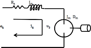
In the analysis of DC motors, the equations for the motor indicate the presence of two time constants; these are related to transfer function of the motor. One is a mechanical time constant and the other is an electrical time constant. Also these two time constants are related to armature resistance and in- ductance, motor torque constant, back EMF constant and equivalent inertia constant. The equivalent circuit diagram and equations are derived below [6].
+
+
But this work presents an assumption of values of different
parameters, to design a motor model at the time of construct- T
ing it, for which the speed of motor can be achieved quickly at
steady position with less overshoot, settling time, steady state - - time and rise time for maximum speed.
The effect major parameters related to motor, armature re- sistance (Ra), armature inductance (La), motor torque constant (Kt), back EMF constant (Ke), equivalent viscous damping coefficient (Dm), equivalent inertia coefficient (Jm), electrical time constant (te), mechanical time constant (tm), have been simulated using MATLAB program to assume the ideal values of the parameters so that almost precise speed motor can be constructed without using controllers. The following sections
Where,
ea(t)= Applied armature voltage (Volts)
ia(t)= Applied armature current (Amps) Jm= Equivalent inertia constant (Kg-m2)
Dm= Equivalent viscous damping constant (N- m-s/rad) Kt= Motor torque constant (N-m/A)
Ke= Motor back EMF constant (V/rad/sec) Vm= Motor velocity (rad/sec)
IJSER © 2013
http://www.ijser.org
The research paper published by IJSER journal is about Design Approach of Improved Response DC Motor Analyzing Motor Characteristics in terms of Electrical and Mechanical Constants with Control Engineering Parameters 2
ISSN 2229-5518
T= Motor torque (N-m)
Ra= Armature resistance (Ω)

La= Armature inductance (Ω)
= Back EMF of motor (volts)

Vm
e R J L
1


K e
D R L
R J J D
a a m a S 2 m a a a m S m m 1
According to KVL-
K t K e Ra
K t K e Ra
K t K e
K t K e
(1)
Since the current-carrying armature is rotating in the magnetic field, its voltage is proportional to speed. Thus, for back EMF of motor is-

Vm
ea t
t S 2 t
1


K e
t e t m
S (t d
1)
(7)
 (2)
(2)
Where the mechanical time constant is

t Ra J m
(8)
So the equation is-
K t K e

ea 1 S
La

ia Ra K eVm
Ra
(3)
and electrical time constant is
t La
e R
(9)
The torque is developed by the motor is proportional to the armature current; thus,
a
And the damping factor is
T Kt ia
(4)

= 0.5 tm
te
(10)

Where T is the torque developed by the motor, and is
the constant of proportionality, called the motor torque constant, which depends on the motor and magnetic field

characteristics. In a consistent set of units, the value of
In block diagram, the transfer function can be represented as

is equal to the value of . ea
. ea
Vm

Transfer function

SJ mVm DmVm a
t
(5)
(6)
3 SIMULATED RESULT
ea 1 S


La SJ mVm DmVm
Ra K eVm
Guidance for choosing data to construct a better response
DC motor, transfer function has been simulated varying dif-

Vm
ea
Ra
Ra

SJ m
Dm
K t
L


1

K e
a S
J m R

a S

J m Dm 1
ferent parameters and thus the best value of a parameter can be approximated for the design of a motor. In terms of control engineering parameters and supplying step input to the mo- tor, the output response has been observed; these are ex- plained below successively.
K t K e
Ra
K t K e
K t K e
IJSER © 2013
http://www.ijser.org
The research paper published by IJSER journal is about Design Approach of Improved Response DC Motor Analyzing Motor Characteristics in terms of Electrical and Mechanical Constants with Control Engineering Parameters 3
ISSN 2229-5518
3.1 Variation of Armature Resistance (Ra) Only
3.2 Variation of Armature Inductance (La) Only
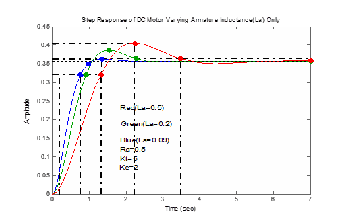
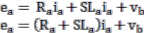
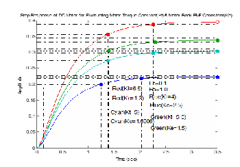
Fig.1. Step response varying armature resistance only
TABLE 1
VALUES OF CONTROLLED PARAMETERS
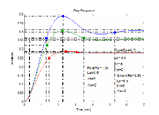
Fig.2. Step response varying armature inductance only
TABLE 3
VALUES OF CONTROLLED PARAMETERS
Obs. | % OS | tr Rise time (Sec) | tp Peak Time (Sec) | ts Set- tling Time (sec) | tss Stead y State time (sec) | Steady State Output |
Blue Curve | 21 | 0.979 | 2.27 | 5.31 | 7 | 0.42 |
Green Curve | 13.5 | 1.03 | 2.24 | 3.47 | 7 | 0.36 |
Red Curve | 3.22 | 1.19 | 2.42 | 3.07 | 4.5 | 0.275 |
TABLE 2
VALUES OF CONSTANTS RELATED TO MOTOR
TABLE 4
VALUES OF CONSTANTS RELATED TO MOTOR
Obs. | Ra | La | te | Kt | Ke | Dm | Jm | tm |
Blue Curve | 0.3 | 0.5 | 1.67 | 5 | 2 | 8 | 10 | 0.3 |
Green Curve | 0.5 | 0.5 | 1 | 5 | 2 | 8 | 10 | 0.5 |
Red Curve | 1.0 | 0.5 | 0.5 | 5 | 2 | 8 | 10 | 1 |
From the fig.1, table 1 and table 2, we observe that if arma- ture resistance is increased then overshoot, steady state time and settling time gradually decrease. And in this case the speed of motor decreases for carrying same load. But rise time increases for both cases, though the electrical time constant is deviated from unity. Even, if we increase the armature re- sistance gradually, once the motor will reach into shut down condition.
From the fig.2, table 3 and table 4, in variation of armature inductance towards increasing, peak time, settling time, rise time, steady state time all increase. But speed at steady state is the same in all cases. For increasing the armature inductance, overshoot increases until a certain value then decreases but other parameters are caused to problem.
IJSER © 2013
http://www.ijser.org
The research paper published by IJSER journal is about Design Approach of Improved Response DC Motor Analyzing Motor Characteristics in terms of Electrical and Mechanical Constants with Control Engineering Parameters 4
ISSN 2229-5518
3.3 Variation of Torque Constant (Kt)
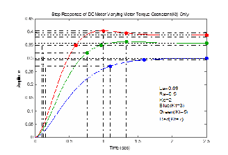
Fig.3. Step response varying torque constant
TABLE 5
VALUES OF CONTROLLED PARAMETRS
3.4 Variation of Motor Back EMF Constant (Ke)
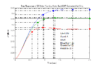
Fig.4. Step response varying motor back EMF constant
TABLE 7
VALUES OF CONTROLLED PARAMETRS
Obs. | % OS | tr Rise time (Sec.) | tp Peak Time (Sec.) | ts Settling Time (Sec.) | tss Steady State time (Sec.) | Steady State Output |
Blue Curve | 0.005 | 0.94 | >2.5 | 1.59 | 2.5 | 0.3 |
Green Curve | 1.39 | 0.632 | 1.33 | 0.964 | 2.5 | 0.357 |
Red Curve | 4.19 | 0.484 | 1.0 | 1.33 | 2.0 | 0.389 |
TABLE 6
VALUES OF CONSTANTS RELATED TO MOTOR
Obs. | Ra | La | te | Kt | Ke | Dm | Jm | tm |
Blue Curve | 0.5 | 0.09 | 0.18 | 3 | 2 | 8 | 10 | 0.833 |
Green Curve | 0.5 | 0.09 | 0.18 | 5 | 2 | 8 | 10 | 0.5 |
Red Curve | 0.5 | 0.09 | 0.18 | 7 | 2 | 8 | 10 | 0.357 |
From the fig.3, table 5 and table 6, for increasing the value of motor torque constant which is related to motor size and material property, rise time, peak time, steady state time de- crease but settling time is fluctuating. In this case steady state output is increased with increasing overshoot.
TABLE 8
VALUES OF CONSTANTS RELATED TO MOTOR
Obs. | Ra | La | te | Kt | Ke | Dm | Jm | tm |
Blue Curve | 0.5 | 0.09 | 0.18 | 5 | 1.5 | 8 | 10 | 0.667 |
Green Curve | 0.5 | 0.09 | 0.18 | 5 | 2 | 8 | 10 | 0.5 |
Red Curve | 0.5 | 0.09 | 0.18 | 5 | 3 | 8 | 10 | 0.333 |
From the fig.4, table 7 and table 8, if we change the value of motor back EMF constant towards increasing then the rise time, peak time, steady state output decrease. But the settling time decreases with fluctuation of its magnitude with respect to increasing motor back EMF constant. In this case, overshoot
and steady state time increase.
IJSER © 2013
http://www.ijser.org
The research paper published by IJSER journal is about Design Approach of Improved Response DC Motor Analyzing Motor Characteristics in terms of Electrical and Mechanical Constants with Control Engineering Parameters 5
ISSN 2229-5518
VALUES OF CONSTANTS RELATED TO MOTOR
3.5 Varying Torque Constant Increasing but Back EMF Constant Decreasing
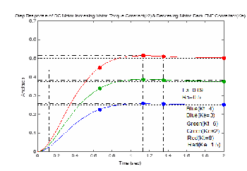
Fig.5. Step response varying Torque Constant Increasing but Back EMF Constant Decreasing
From the fig.5, in case of increasing the torque constant and decreasing back EMF constant such that the multiplication of both constants is same so that mechanical time constant is not change due to changing the constants, overshoot, rise time, peak time, settling time and steady state time are not change. But the speed of motor is increased owing to increasing torque constant though back EMF constant is increasing.
TABLE 9
VALUES OF CONTROLLED PARAMETRS
So, from the table 9 and table 10, it can be concluded that the control engineering parameters have no effect on both of the constants rather the effect of changing these parameters is the change of mechanical time constant as it is the function of torque constant and back EMF constant. On the other hand, steady state output is directly related to these constants.
3.6 Fuctuating Torque Constant and Back EMF Con- stant such that Mechanical Time Constant is Grearer than Unity
Fig.6. Step response fluctuaing torque constant and back EMF constant
TABLE 11
VALUES OF CONTROLLED PARAMETRS
TABLE 12
VALUES OF CONSTANTS RELATED TO MOTOR
TABLE 10
IJSER © 2013
http://www.ijser.org
The research paper published by IJSER journal is about Design Approach of Improved Response DC Motor Analyzing Motor Characteristics in terms of Electrical and Mechanical Constants with Control Engineering Parameters 6
ISSN 2229-5518
Curve | | | | | | | | |
Cyan Curve | 1 | 0.1 | 0.1 | 5 | 1.7 | 8 | 10 | 1.183 |
As already explained that there is no effect of mechanical time constant on steady state output and steady state output has proportional effect on torque constant and inverse propor- tional effect on back EMF constant. So, from the fig.6, table 11 and table 12, it is shown that if the value of torque constant and back EMF constant are changed at same time, the effect is the same as these are changed individually. The effects on rise time, overshoot, peak time and steady state time are same though constants are changed individually.
3.7 Fuctuating Torque Constant and Back EMF Con- stant such that Mechanical Time Constant is Less than Unity
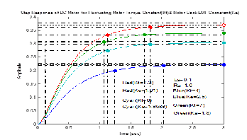
Fig.7. Step response fluctuaing torque constant and back EMF constant
TABLE 13
VALUES OF CONTROLLED PARAMETRS
TABLE 14
VALUES OF CONSTANTS RELATED TO MOTOR
Obs. | R a | La | te | Kt | Ke | Dm | Jm | tm |
Blue Curve | 1 | 0.1 | 0.1 | 4 | 2.5 | 8 | 10 | 1 |
Green Curve | 1 | 0.1 | 0.1 | 7 | 1.8 | 8 | 10 | 0.794 |
Red Curve | 1 | 0.1 | 0.1 | 7.3 | 1.61 | 8 | 10 | 0.851 |
Cyan Curve | 1 | 0.1 | 0.1 | 6 | 1.959 | 8 | 10 | 0.851 |
In this case also steady state output is proportional to the torque constant and inverse proportional to back EMF con- stant though the mechanical time constant is less than unity.
So, mechanical time constant has no effect on steady state out- put rather than torque constant and back EMF constant.
On the contrary, when mechanical time constant is changed under unity, rise time, peak time, steady state time and set- tling time are changed similarly as explained before. But there is no change in these parameters when there is no change in mechanical time constant.
3.8 Varying Equivalent Viscous Damping Coefficient
(Dm)
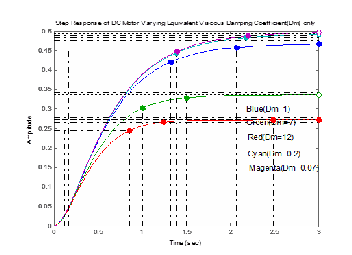
Fig.8. Step response varying equivalent viscous damping coefficient
IJSER © 2013
http://www.ijser.org
The research paper published by IJSER journal is about Design Approach of Improved Response DC Motor Analyzing Motor Characteristics in terms of Electrical and Mechanical Constants with Control Engineering Parameters 7
ISSN 2229-5518
TABLE 15
VALUES OF CONTROLLED PARAMETRS
TABLE 16
VALUES OF CONSTANTS RELATED TO MOTOR
is increased. If equivalent viscous damping coefficient is de- creased, speed of motor reaches at maximum possible stage and then speed is not changed with decreasing equivalent viscous damping coefficient.
Peak time becomes minimum for a particular value of equivalent viscous damping coefficient depending on the size and gear of motor. After that if we increase or decrease the value of equivalent viscous damping coefficient, peak time is increased.
3.9 Varying Equivalent Inertia Coefficient (Jm)
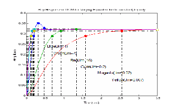
Fig.9. Step response varying equivalent inertia coefficient
TABLE 17
VALUES OF CONTROLLED PARAMETRS
From the fig.8, table 15 and table 16, it is shown that if equivalent viscous damping coefficient is increased, overshoot becomes zero with fluctuation of its magnitude. So, one peak of overshoot is greater than the next successive one and thus overshoot becomes zero. That means for excessive viscous friction, motor will not rotate.
Again, if equivalent viscous damping coefficient is de- creased, overshoot becomes zero with fluctuation of its magni- tude. So, one peak of overshoot is greater than the next succes- sive one and thus overshoot becomes zero.
With increasing equivalent viscous damping coefficient, rise time and settling time are decreased but steady state time
IJSER © 2013
http://www.ijser.org
The research paper published by IJSER journal is about Design Approach of Improved Response DC Motor Analyzing Motor Characteristics in terms of Electrical and Mechanical Constants with Control Engineering Parameters 8
ISSN 2229-5518
low. Choice of equivalent viscous damping coefficient is better when its range is towards as maximum low as possible. Be- sides, low level but towards unity is better choice of motor inertia constant.
TABLE 18
VALUES OF CONSTANTS RELATED TO MOTOR
Acknowledgment
The authors wish to thank Mr. Md. Shanowar Hossain who has helped us in different ways and continiously encouraged us.
REFERENCES
From the fig.9, table 17 and table 18, it is observed that, at unity equivalent inertia coefficient, overshoot becomes maxi- mum. But when equivalent inertia coefficient is deviated from unity towards either decreasing or increasing; overshoot be- comes zero with fluctuation of its magnitude within small range. So, one peak of overshoot is greater than the next suc- cessive one and thus overshoot becomes zero.
Again, if equivalent inertia coefficient is increased from unity, rise time is increased and if equivalent inertia coefficient is decreased from unity, rise time is decreased until a particu- lar value and then it fluctuates within a very small range.
Settling time and peak time become minimum at maximum overshoot and then if equivalent inertia coefficient is increased or decreased, both the time parameters are increased at maxi- mum possible stage. But at maximum overshoot, steady state time is minimum and all other cases cause gradual increase in steady state time.
4 DESIGN CONCLUSION
In conclusion, for design a more perfect DC motor whose characteristics will be suitable for using in very precise works, it should be kept in minds which have been explained throughout the paper. For adjusting the parameters so far ex- plained, resistance should be chosen around middle of unity in accordance with motor size and armature inductance should be kept as low as possible for better response.
Motor torque constant should be kept as moderately high as possible in accordance with the size of motor and better suited level of motor back EMF constant’s value is moderately
AUTHOR’S BIOGRAPHIES
Md. Ilius Hasan Pathan has completed his Bachelor of Science in Electri- cal and Electronic Engineering from Rajshahi University of Engineering & Technology (RUET), Rajshahi-6204, Bangladesh.Currently; he is a Lecturer of Electrical Engineering department at Bangladesh University of Business
& Technology (BUBT), Dhaka, Bangladesh. The author’s has total number
of two publications & one text book on microstrip patch antenna which has been published in Amazon.com. His teaching and interests of re- search areas include power system and Industrial control, FACTS devices, power electronics, process control, PLC application, Power system plan- ning, operation & optimization and Smart Grid(Email:pmilius2501@gmail.com).
Md. Zulfiker Heider has completed his Bachelor of Science in Electrical and Electronic Engineering from Rajshahi University of Engineering & Technology (RUET), Rajshahi-6204, Bangladesh Currently; he is an Assis- tant Engineer of Telephone Shilpa Shongstha Limited which is a Govern- ment Telecom Products Manufacturing company of Bangladesh .His interests of research areas include Efficient Power Transmission, FACTS devices, Sub-station Design, PLC application and Smart Grid (Email: zulfiker_ruet06@yahoo.com)
Md. Rakibul Hasan Pathan: is a technician has knowledge in different electrical equipments and he is expert in making different electrical devic-
IJSER © 2013
http://www.ijser.org
International Journal of Scientific & Engineering Research Volume 4, Issue 2, February-2013 9
ISSN 2229-5518
es. His interests of research areas include power system, industrial control and motor drives. (E-mail: pmrakibul@gmail.com)
IJSER lb)2013
http://www .'lser.ora