International Journal of Scientific & Engineering Research, Volume 6, Issue 3, March-2015 836
ISSN 2229-5518
DESIGN OF MB-OFDM SYSTEM USING HDL
Ms. Payal Kantute, Mrs. Jaya Ingole
Abstract - Multi-Band Orthogonal Frequency Division Multiplexing (MB-OFDM) is a suitable solution for implementation of high speed data transmission in ultra wideband spectrum by dividing the spectrum into available multiple bands. In MB-OFDM system the most important part is base band of transmitter. The standard aims at the high data transmission rates of110 Mb/s over 10 meters, 220 Mb/s over 4 meters and 480Mb/s over 1 meter. The structure of MB-OFDM system transmitter using HDL is introduced in this paper .The design has been validated with active HDL.The results show that all modules designed has achieved the expected purpose both in precision and resource, with simplicity and high efficiency and can meet the demand of MB-OFDM transmitter baseband base systems.
Index Terms - OFDM, UW B, Scrambler, Encoder, Puncturer, Interleaver, QPSK, IFFT
—————————— ——————————
Multi-Band Orthogonal Frequency Division Multiplexing (MB-OFDM) [1,2] is a suitable solution to implementation of high speed data transmission in ultra wideband spectrum by dividing the spectrum available into multiple bands. MB-OFDM is a multi-carrier system where data bits are encoded to multiple sub-carriers, while being sent simultaneously. This results in the optimal usage of bandwidth. A set of orthogonal sub-carriers together forms an OFDM symbol. To avoid ISI due to multi-path, successive OFDM symbols are separated by guard band. This makes the OFDM system resistant to multi-path effects. The baseband of transmitter is one of the most important parts in MB-OFDM system. The structure of MB-OFDM system transmitter is introduced in this section. In recent years, UWB[3] communication systems have received significant attention from both the industry and the academia. In February 2002, the Federal Communications Commission (FCC) allocated 7,500 MHz of spectrum (from 3.1 GHz to 10.6 GHz) for use by UWB devices [4]. This ruling has helped to create new standardization efforts, like IEEE 802.15.3a [5], that focus on developing high speed wireless communication systems for personal area network. A multi-band orthogonal frequency division
multiplexing (MB-OFDM) ultra wideband (UWB)
system is being considered for the physical layer of the new IEEE wireless personal area network (WPAN) standard, IEEE 802.15.3a. The standard aims at the high data transmission rates of110 Mb/s over 10 meters, 220 Mb/s over 4 meters and
480Mb/s over 1 meter [4]. Field programmable gate array (FPGA) technology[6] is not only a key technology in digital system, but also plays an important role in application specific integrated circuit (ASIC) design field because of its design flexibility, and higher integration . The technical line for the implementation of MB-OFDM transmitter baseband module with Active HDL software is introduced in this paper. It has been proved by the simulation results that the design of MB-OFDM transmitter baseband based on FPGA has good characterizes such as simple structure, easy implementation, high reliability and so on.
BEQILSPIDIFnNOnaPucAFtPcser/nSTCVaUorcKlmCbdTteuaOeabDrnrvleeAderrrTA
![]()
IJSER © 2015 http://www.ijser.org
International Journal of Scientific & Engineering Research, Volume 6, Issue 3, March-2015 837
ISSN 2229-5518
The aim of this project is to design MB- OFDM transmitter baseband base system using HDL.Basically we are implementing the digital baseband blocks of MB-OFDM transmitter [1] and its major components as follows & it is implemented with the help of VHDL code.
In telecommunications, a scrambler is a device that transposes or inverts signals or otherwise encodes a message at the transmitter to make the message unintelligible at a receiver not equipped with an appropriately set descrambling device.
Types of Scramblers:
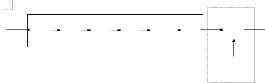
Additive scramblers transform the input data stream by applying a pseudo-random binary sequence (PRBS) (by modulo-two addition). For the synchronous operation of the transmitting and receiving LFSR (that is, scrambler and descrambler), a sync-word must be us.Additive scrambler/descrambler is defined by the polynomial of its LFSR is (1+x-14 +x-15 ) and its initial state.
![]()
1S191234567810O101I01245NYUNTC
![]()
![]()
![]()
![]()
![]()
![]()
![]()
![]()
![]()
![]()
![]()
![]()
![]()
![]()
![]()
![]()
![]()
![]()

![]()
![]()
Multiplicative scramblers perform a multiplication of the input signal by the scrambler's transfer function in Z-space. They are discrete linear time-invariant systems. A multiplicative scrambler is recursive and a multiplicative descrambler is non-recursive.They do not need the frame synchronization, hence called self-synchronizing. Multiplicative
scrambler/descrambler is defined similarly by a polynomial (for the scrambler in![]()
![]()
the figure it is (1+x-18+x-23 )), which is also a transfer function of the descrambler.![]()
![]()
![]()
In telecommunication, convolution code[7,8] is a type of error-correcting code in which each m- bit information symbol (each m-bit stream) to be encoded is transformed into an n bit symbol, where m/n is the code rate ( n>m). The transformation is a function of the k information symbols. Here we have used convolutional encoder.![]()
(nmn112,10101,1)

![]()
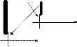
The Figure shown above is a rate 1/3 (m/n) encoder with constraint length (k) of 3. Generator polynomials are G1 = (1, 1, 1), G2 = (0, 1, 1), and G3
= (1, 0, 1). Therefore, output bits are calculated
(modulo 2) as follows:
1. n1 = m1 + m0 + m-1
2. n2 = m0 + m-1
3. n3 = m1 + m-1.
Puncturing is the process of removing
IJSER © 2015 http://www.ijser.org
International Journal of Scientific & Engineering Research, Volume 6, Issue 3, March-2015 838
ISSN 2229-5518
![]()
![]()
some of the redundant bits after encoding with an error-correction coding technique. Suppose L or![]()
SIn/Pput Data
![]()
![]()
![]()
NL bits of the output for convolution encoder, the
puncturing matrix P with NL symbols is defined as
a binary array, where “1” denotes the data that is sent out and “0” denotes the data that is deleted. If P has m zeros, the code rate after puncturing is L/(NL-m), where 0 ≤ m ≤ (N −1)L , L is the input of convolution encoder.![]()
![]()
![]()
![]()
![]()
CPNuoLncvmtoulutetrional Encoder
Writing the symbols in the constellation diagram
![]()
![]()
in terms of the sine and cosine waves used to transmit them:
![]()
![]()
S (t) = 2Es
Ts
cos(2πfc t + �2n-1�
![]()
![]()
π) ,
4
n = 1,2,3,4.
This results in a two-dimensional signal space with unit basis functions
Interleaving is a process that makes a
system more efficient, fast and reliable by arranging data in a noncontiguous manner.Also it is a device that rearranges the ordering of sequence of symbols in a deterministic manner.![]()
Φ1 (t) =
![]()
2
![]()
Φ2 (t) = �
Ts
sin(2πfct)
![]()
![]()
![]()

![]()
![]()
INTERLEAVER
The first basis function is used as the in-phase component of the signal and the second as the
quadrature component of the signal.Hence, the signal constellation consists of the signal-space 4 points

![]()

![]()
IFFT is a core of the baseband of MB- OFDM transmitter. The bit streams will be
modulated on various frequencies carrier by IFFT, initially carrier bank generating a set of subcarriers was necessary for OFDM in conventional or
QPSK uses four points on the constellation
![]()
diagram, equispaced around a circle. QPSK is used to double the data rate as compared to BPSK.The coded and interleaved binary serial input data shall be divided into groups of two bits and converted into a complex number representing one of the four QPSK [9] constellation points.The conversion shall be performed according to the Gray-coded constellation mapping. The mapping relation of QPSK module is illustrated as in figure.
analogue approach. Each subcarrier was
modulated with a constellation decided by bit
combination, but this approach made system bulky and costlier. So to make system digital, simple, cheap, and efficient IFFT is being used. The N- Point IFFT [10, 11] is shown in the figure below.![]()
![]()
![]()
.Xx..((01N1N0)))-1)
![]()
IJSER © 2015 http://www.ijser.org
International Journal of Scientific & Engineering Research, Volume 6, Issue 3, March-2015 839
ISSN 2229-5518
Using the design methods above, the simulation of each module for MB-OFDM transmitter baseband which has been validated with Active HDL is given. The following are the simulation results of the prime building blocks of the OFDM transmitter baseband base system.
The input data stream is given to the scrambler. The simulation of scrambler is shown in the figure.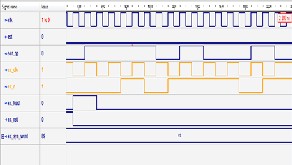
The output of scrambler is given to the input of encoder because of which the bit rate increases.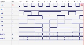
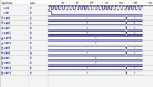
The simulation results of the puncturer are shown below in figure consisting two bit streams as input and providing only one punctured bit stream as output,which clearly shows that the bit rate is increased , it is shown below.
The output of puncture is given to the input of interleaver. It is a device that rearranges the ordering of sequence of symbols in a deterministic manner.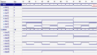
IJSER © 2015 http://www.ijser.org
International Journal of Scientific & Engineering Research, Volume 6, Issue 3, March-2015 840
ISSN 2229-5518
base system. It provides the basis for the design of MB-OFDM system. This approach can also be used to design other high-speed communication systems or to improve their speed.
After IFFT block the complete baseband simulation will be observed which clearly indicates the multiple outputs , hence showing digitally the multiple bands of the system. The complete baseband simulation observed after the last block of the OFDM baseband system is shown in figure above.
In this paper, an efficient way to design the IEEE 802 MB-OFDM transmitter baseband base system is presented. We have used VHDL coding to design each module of transmitter baseband for MB-OFDM with the help of Active HDL software
.The paper presents about scrambler, encoder, puncture, interleaver, QPSK and IFFT. The simulation results indicate that the timing of each module is true and the results can meet the requirement of MB-OFDM transmitter baseband
[1] J. Balakrishnan, A. Batra, A. Dabak, A multi- band OFDM system for UWB communication,
IEEE Conference on Ultra Wideband Systems and
Technologies, 2003, pp. 354–358.
[2] A. Batra, J. Balakrishnan, A. Dabak, and et al, MultiBand OFDM Physical Layer Proposal for IEEE 802.15.3a, http://www.multibandofdm.org/presentations. html, MultiBand OFDM Alliance SIG, 2004.
[3] First report and order in the matter of revision of part 15 of the commissions rules regarding ultra-wideband transmission systems, Federal Communications Commission (FCC 02-48), std., ET Docket 98-153, Apr. 2002.
[4] Anuj Batra, et al., “Design of a Multiband OFDM System for Realistic UWB Channel Environments ”, IEEE TRANSACTIONS ON MICROWAVE THEORY AND TECHNIQUES, VOL. 52, NO. 9, SEPTEMBER 2004.
[5] ISO/IEC, “Information technology Telecommunications and information exchange between systems — High Rate Ultra Wideband PHY and MAC Standard”, 26907, Mar.2007, pp 15-59.
[6] Ray Andraka, “A survey of Cordic algorithms for FPGA based computers”, Andraka Consulting Group, Inc,1998, pp1-10.
[7] Yunghsiang S. Han, \Introduction to Binary Convolutional Codes", Graduate Institute of Communication Engineering, National Taipei University.
[8] Dr. Chih-Peng Li, \Convolutional Codes",
National sin-Yat University ,Wireless information transmission system lab.
[9] ”Introduction to Quadrature Phase Shift Keying” http://www.en.wikipedia.org/wiki/Phaseshift_ keying
[10] M. Mohamed Ismail ,M.J.S Rangachar , Ch. D.
V. Paradesi Rao “An Area Efficient Mixed- Radix 4-2 Butterfly with Bit Reversal for OFDM Applications” Proposed processor
IJSER © 2015 http://www.ijser.org
International Journal of Scientific & Engineering Research, Volume 6, Issue 3, March-2015 841
ISSN 2229-5518
architecture that can greatly save the area cost with high-speed .They also give detail analysis
of several FFT algorithms such as radix-2, radix-4 and split radix are given.
[11] A. Corts, I. Vlez, M. Turrillas and J. F.
Sevillano, \ Fast Fourier Transform
Processors: Implementing FFT and IFFT
Cores for OFDM Com munication Systems", TECNUN (Universidad de Navarra) and CEIT Spain,www.intechopen.com.
[12]Wu Weiling,et,al. “Mobile Communication
Principle”,Publishing house of electronics
industry. Beijing, 2005,pp.161-170.
[13]ISO/IEC, “Information technology
Telecommunications and informationexchange between systems — High Rate Ultra Wideband PHY andMAC Standard”, 26907, Mar.2007, pp 15-59. Davinder Pal
Sharma,Jasvir Singh, \DSP Based
Implementation of Scrambler for 56Kbps
Modem", Signal Processing An International
Journal (SPIJ), Vol-4 (2), pp 85-96.
Department of EXTC, PRMIT&R College of Engineering Badnera, Amravati, Maharashtra, India.
Associate Professor in PRMIT&R College of Engineering Badnera, Amravati, Maharashtra, India.
IJSER © 2015 http://www.ijser.org