International Journal of Scientific & Engineering Research, Volume 4, Issue 7, July-2013 288
ISSN 2229-5518
1(M.Tech, Communication and Radar systems, ECE, K.L. University, India)
2(Head of the ECE department, K.L. University, India)
3(Scientist-SF, National Atmospheric Research Laboratory, Gadanki, India)
![]()
![]()
In this paper the array of Dual feed Micro strip Patch antenna which operates at 5GHz has been discussed in details. Microstrip patch antenna has been received tremendous attention since the last two decades and now it becomes a major component in the development of Wind Profile Radar. Microstrip antenna is a printed type antenna consisting of a dielectric substrate sandwiched in between a ground plane and a patch.
Fig1: A Typical Microstrip Patch Antenna
In this project Micro strip patch antenna technology is used for designing of the antenna suitable for WPR Because of its commercial reality with applications in wide variety of microwave systems, Personnel communication system(PCS), wireless local area network (WLAN) etc. These are preferred over other types of radiators because of its low profile and light weight but its major drawback is its narrow bandwidth and low gain. This is one of the problems that researchers around the world have been trying to overcome. In this project, we have tried to increase the gain and bandwidth of the patch antenna. It has been noticed that there is some significant increments in bandwidth and gain measurements.
IJSER © 2013 http://www.ijser.org
International Journal of Scientific & Engineering Research, Volume 4, Issue 7, July-2013 289
ISSN 2229-5518
A micro strip or patch antenna is a low profile antenna that has a number of advantages over other antennas it is light weight, inexpensive, and easy to integrate with accompanying electronics. While the antenna can be
3D in structure (wrapped around an object, for example), the elements are usually flat hence their other name, planar antennas.
Looking at the current (magnetic field) and voltage (electrical field) variation along the patch, the current is maximal at the center and minimal near the left and right edges, while the electrical field is zero in the center and maximal near the left and minimal near the right edges. The figures below clarify these quantities.
The patch's radiation at the fringing fields results in a certain far field radiation pattern. This radiation pattern shows that the antenna radiates more power in
a certain direction than another direction. The antenna is said to have certain directivity. This is commonly expressed in dB. The rectangular patch excited in its fundamental mode has a maximum directivity in the direction perpendicular to the patch (broadside). The directivity decreases when moving away from broadside towards lower elevations. The 3 dB beam width (or angular width) is twice the angle with respect to the angle of the maximum directivity, where this directivity has rolled off 3 dB with respect to the maximum directivity.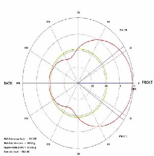
Antenna gain is defined as antenna directivity times a factor representing the radiation efficiency. This efficiency is defined as the ratio of the radiated power (Pr) to the input power (Pi). The input power is transformed into radiated power and surface wave power while a small portion is dissipated due to conductor and dielectric losses of the materials used. Surface waves are guided waves captured within the substrate and partially radiated and reflected back at the substrate edges. Surface waves are more easily excited when materials with higher dielectric constants and/or thicker materials are used. Surface waves are not excited when air dielectric is used. Antenna gain can also be specified using the total efficiency instead of the radiation efficiency only. This total efficiency is a combination of the radiation efficiency and efficiency linked to the impedance matching of the antenna.
This is the frequency range wherein the structure has a usable bandwidth compared to certain impedance,
IJSER © 2013 http://www.ijser.org
International Journal of Scientific & Engineering Research, Volume 4, Issue 7, July-2013 290
ISSN 2229-5518

usually 50 Ω. The impedance bandwidth depends on a large number of parameters related to the patch antenna element itself (e.g., quality factor) and the type of feed used. The plot below shows the return loss of a patch antenna and indicates the return loss bandwidth at the desired (S11/VSWR). The bandwidth is typically limited to a few percent. This is the major disadvantage of basic patch antennas.
Wind profiler radars are vertically directed pulsed Doppler radars capable of analysing the back-scattered signals to determine the velocity of air along the beams. By steering the beams typically 15° from zenith, the horizontal and vertical components of the air motion can be obtained.
Another approach is to see the patch as a parallel RLC resonant circuit. This means a phase shift that changes versus frequency is present, as shown in the following plot:
Wind profilers depend upon the scattering of electromagnetic energy by minor irregularities in the refractive index of air. The reflective index is a measure of the speed at which electromagnetic wave propagates through a medium. Atmosphere is the medium for wind profiling. A spatial variation in this index encountered by a radio wave causes a minute amount of energy to be scattered in all direction.
In this atmosphere, minor irregularities in the refractive index exist over a wide range of sizes in the troposphere and stratosphere. The refractive index depends primarily on the temperature, pressure and humidity of the air. The radar depends on the scattering of EM wave energy of the air associated with clear air turbulence (CAT). The atmosphere minor irregularities in the index refraction exist over a wide range of refraction sizes.
The wind, as it varies in direction or speed produce turbulent eddies(small whirling currents of air). The turbulent eddies are created over a spectrum of sizes ranging from many tens of metres down to centimetres.
Radar systems for weather forecasting purposes are to be accommodated in the frequency allocations of the radiolocation service and/or the meteorological aids service. Existing uses in these bands need to be protected and compatibility with the services in the adjacent bands has to be assured. On the other hand, accommodation in the frequency bands of other radio services could be considered, if this is acceptable from a frequency-sharing point of view.
For the identification of the various compatibility and/or sharing options, a clear understanding of the concept of wind profiler radar systems and their behaviour in the electromagnetic environment is needed.
The important applications of a conventional Wind Profile Radar lies in (i) Short range forecasting, (ii) Convective storm initiation, (iii) Climates, (iv) Air Pollution, (v) Aviation operations and flight planning, and (vi) Rocket and missile launching etc.
IJSER © 2013 http://www.ijser.org
International Journal of Scientific & Engineering Research, Volume 4, Issue 7, July-2013 291
ISSN 2229-5518

(a) ADS is an EM Design Kit for real-time full-wave
EM tuning, optimization and synthesis.
(b) Multi-fold speed improvement and multi-CPU
support for much improved efficiency.
(c) Equation-based schematic-layout editor with Boolean operations for easy and flexible geometry editing and parameterization.
(d) Lumped element equivalent circuit automatic extraction and optimization for convenient circuit designs.
(e) Improved integration into Microwave Office from
Applied Wave Research.
(a) Planar antennas such as micro strip antennas and slot antennas.
(b) Wire antennas such as various types of dipole, monopole, helix and quadrifilar antennas.
(c) Small antennas such as inverted-F antennas and its derivations.
(d) Dielectric resonator antennas. (e) RFID antennas.
(f) Optical frequency antennas. (g) Many other types of antennas.
In this paper, selected parameters are: Resonant Frequency = 5 GHz(C band), Dielectric material is RT-DUROID5880, Dielectric constant €r = 2.2, Height of the dielectric substrate h = 1.575 mm. The dimension of the Square Patch is 0.0001 mm layout resolution, tan ∂ = 0.0004
Fig.2: Single element Patch Layout structure.
Meshing parameters are Fmax = 6 GHz, N cells = 20 cells/λ, mesh reduction is normal.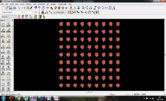
Fig.3: 9x9 patch antenna array layout structure
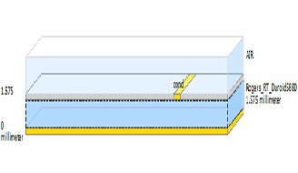
Fig.3(a): Substrate layout of patch antenna
IJSER © 2013 http://www.ijser.org
International Journal of Scientific & Engineering Research, Volume 4, Issue 7, July-2013 292
ISSN 2229-5518
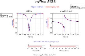
Fig. 4: Return Loss vs frequency plot for patch antenna array element at center element
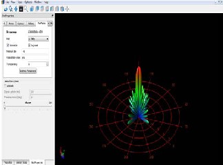
Fig. 6(b): 3D Radiation Pattern of Patch Antenna
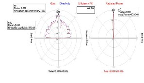
Fig. 5: Gain, Directivity & Radiated power plot
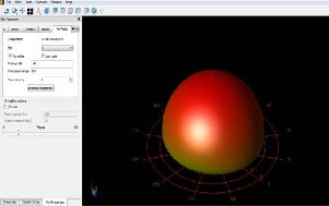
Fig. 6(a): 3D Radiation pattern of single element antenna
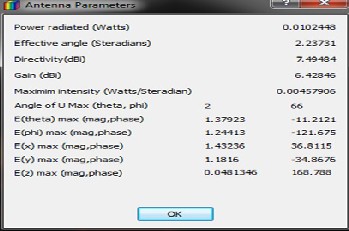
Fig. 7(a): Antenna Parameters of single element antenna

Fig. 7(a): Antenna Parameters of patch antenna array
IJSER © 2013 http://www.ijser.org
International Journal of Scientific & Engineering Research, Volume 4, Issue 7, July-2013 293
ISSN 2229-5518
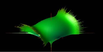
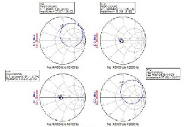
Fig.8 input impedance of single element patch antenna
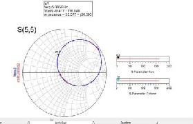
Fig.8(b) input impedance of patch antenna array for center element
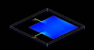
Fig. 9: current distribution of single element patch antenna
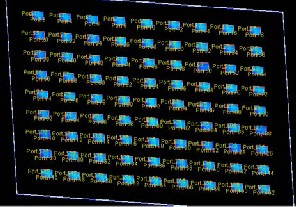
Fig. 9: current distribution of patch antenna array
Fig. 10: 3D linear axial ratio for single element
antenna

Fig. 10: 3D linear axial ratio for patch antenna array
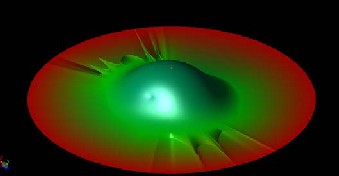
Fig. 11: 3D circular axial ratio for single element patch antenna

Fig. 11: 3D circular axial ratio for patch antenna array
IJSER © 2013 http://www.ijser.org
International Journal of Scientific & Engineering Research, Volume 4, Issue 7, July-2013 294
ISSN 2229-5518
PARAMETER S | SINGLE ELEMENT array | 9x9 PATCH ANTENNA ARRAY | ||||||
PARAMETER S | Pi= 0 | Pi=90 | Theta=0 | Theta=90 | Pi= 0 | Pi=90 | Theta=0 | Theta=90 |
E-Theta | 1.433 | 1.179 | 1.433 | 0.232 | 222.134 | 226.119 | 222.136 | 5.759 |
E-pi | 1.179 | 1.433 | 1.179 | 0.027 | 226.115 | 222.134 | 226.119 | 1.117 |
H-Theta | 0.003 | 0.004 | 0.003 | 7.054E-5 | 0.600 | 0.590 | 0.600 | 0.003 |
H-pi | 0.004 | 0.003 | 0.004 | 6.153E-4 | 0.590 | 0.600 | 0.590 | 0.015 |
Erhp | 5.218 | 5.218 | 5.218 | -15.528 | -33.905 | -33.905 | 46.918 | 11.294 |
Elhp | -9.312 | -9.312 | -9.312 | -15.778 | 47.101 | 47.101 | 47.101 | 13.489 |
Eco | 3.124 | 3.124 | 3.124 | -12.698 | 46.932 | 46.932 | 46.932 | 15.207 |
Ecross | 1.427 | 1.427 | 1.427 | -31.510 | -33.342 | -33.342 | 47.087 | 0.962 |
Tab(1): comparison table of single element and 9x9 micro strip patch antenna array
SPECIFICATIONS | SINGLE ELEMENT | 9X9 ARRAY ANTENNA |
RETURN LOSS | -25.732dB | -18.653 |
GAIN | 6.42dB | 27.246dB |
DIRECTIVITY | 7.49dB | 27.957dB |
RADIATED POWER | 0.005W | 133.346W |
EFFECTIVE ANGLE | 2.23 | 0.020 |
EFFECTIVE AREA | 0.001 | 0.152 |
Tab(2): comparison table of single element and 9x9 micro strip patch antenna array
A major problem with any radar – and a wind profiler radar is no exception – is the large required bandwidth. Under the condition that the separation areas between television stations operating in the same channel are large enough to allow the operation of a wind profiler in this channel and in this separation region, the bandwidth issue is no longer a major concern because the profiler could occupy practically the entire width of the TV channel.
• The data rate will be high and therefore the range resolution is high.
• The pulse compression will be smaller with the increment of frequency bandwidth.
• In mobile and broadband communications, it will be very useful.
• Radiolocation, amateur, space operations, amateur-satellite and aeronautical radiolocation services.
The research motivation of this project is to design dual feed patch antenna array with 81 elements (9x9) for atmospheric Wind Profile Radar application which operates in C-band at 5 GHz. ADS electromagnetic simulator is used for design and simulation of patch Antenna. The 9X9 array square patch antenna with
50ohms line feed has been designed. The impedance bandwidth of the designed antenna is 220 MHz, antenna gain is 27.246 dB, directivity is 27.957 dB, return loss at center element S(5,5) is -18.653 dB, the efficiency obtained is 84.782% . From the radiation pattern, it is observed that use of amplitude taper maintained the SLL within the maximum scan angle limit, which is an added advantage for Atmospheric Wind Profile Radar application. The gain and bandwidth of 9x9 patch array antenna shows the path of further experiments with increase in size of arrays of antennas and with different substrate material selection in the array antenna designing.
The authors of this paper would like to acknowledge all the corresponding IEEE paper holders and most importantly the publishers of related books and journals which gave immense support and inspiration in preparing this manuscript. Above all, the extreme mental support and source of inspiration from all the family members and friends are widely acknowledged.
[1] Srinivasulu. P, Manas R Padhy, Yasodha. P and Nara yanaRao. T, 2010 “Development of UHF wind profiling radar for lower atmospheric research applications”. Conference paper at NARL.
[2] Srinivasulu. P, Yasodha. P, Rajendra Prasad. T
IJSER © 2013 http://www.ijser.org
International Journal of Scientific & Engineering Research, Volume 4, Issue 7, July-2013 295
ISSN 2229-5518

and Narayana Reddy. S 2010 “Development of
1280 MHz Active Array RADAR at NARL”. Conference
Paper at NARL DRAWS-2010.
[3] C.T.P.Song, P.S.Hall and H.G.Shiraz, “Multiband Multiple Ring Monopole Antennas” IEEE Trans. on Antennas and propagation, vol. 51,No.4 pp. 722–729, April. 2003.
[4]. Karaboga, D., K. Guney, S. Sagiroglu, and M. Erler, \Neural computation of resonant frequency of electrically thin and thick rectangular microstrip antennas," IEEE Proceedings | Microwaves, Antennas and Propagation, Vol. 146, No. 2, 155{159, Apr. 1999.
[5]. Mishra, R. K. and A. Patnaik, \Neural network-based CAD model for the design of square-patch antennas," IEEE Trans. on Antennas Propagat., Vol. 46, No. 12, 1890{1891, Dec. 1998.
[6]. Patnaik, A., R. K. Mishra, G. K. Patra, and S. K. Dash, \An arti¯cial neural network model for e®ective dielectric constant of microstrip line," IEEE Trans. on Antennas Propagat., Vol. 45, No.
11, 1697, Nov. 1997.
[7] R. G. Voughan. 1988. Two-port higher mode circular microstrip antennas. IEEE, Trans. Antennas Propagat.36(3):
309-321.
[8] D.D.Sandu, O.Avadanei, A.Ioachima, G.Banciua, P.Gasner. Microstrip Patch Antenna with dielectric substrate. Journal Optoelectronics and Advanced Materials Vol. 5, No. 5, 2003.
 V. HARSHA RAM KEERTHI
born in India, 1990, he is currently pursuing M.Tech in Communications & Radar System Engineering from the Department of Electronics and Communication, K.L University, Vijayawada, A.P, India. Presently he is carrying out his project work on Microstrip Patch Antenna Design from National Atmospheric Research Laboratory (NARL), Gadanki. Department of Space, Govt.of India. He has completed his B.E in Electronics and Communication from Saveetha Engineering College of Electronics, Anna University, Tamilnadu, and India.
1980-84. M.E from C.I.T, Coimbatore during 1985-87 and PhD from Andhra University in the area of antennas in the year 2007.He is having more than 20 years of teaching experience and having more than 20 international, national journals/conference papers in his credit. Dr.Habibullah khan presently working as Head of the ECE department at K.L.University .He is Member Board of Studies in ECE and EIE of Acharya Nagarjuna University, Guntur. He is a fellow of I.E.T.E, Member IE, SEMCE and other bodies like ISTE. His research interested areas includes Antenna system designing, microwave engineering, Electromagnetic and RF system designing
. Dr. P. S RI NI VAS UL U is presently working as Scientist-SF at National Atmospheric Research Laboratory (NARL). He
is involved in the installation an d c o mmis s io n in g of the VHF Indian MST Radar and L -band B o u n d a r y Layer Radar at NAR L . He h as expertise on high power radar transmitters, phased antenna a r r a ys and receivers. Currently he is working on leading active array radar projects in VHF and U H F bands for atmospheric remote sensing application.
IJSER © 2013 http://www.ijser.org