International Journal of Scientific & Engineering Research, Volume 6, Issue 5, May-2015 931
ISSN 2229-5518
Design and Construction of an Inverter Type
3KVA, 50 Hz, Single-Phase Arc Welding
Machine
Engr. Ovbiagele U; Engr. Obaitan B
Abstract : W elding serves a variety of purposes across domains. Machinery and equipment fabrication, pipeline and manifold welding, structural welding, offshore welding and ornamental welding are examples of welding that take place in business and industry. W elding equipment has become one of the most important tools that a producer can possess hence the need to design and construct an arc- welding machine. In this paper, the authors designed and constructed 3KVA, 50 Hz, single-phase arc welding machine using locally available materials. To solve the problem of weight and size of conventional arc welding machine an inverter circuit was also designed. The inverter provides much higher frequency than 50Hz or 60 Hz for transformer used in welding. The locally constructed electric arc welding machine capable of withstanding 150 A, when subjected to insulation test, short circuit and open circuit test to ascertain performance characteristic were very satisfactory.
Keywords: arc welding, equipment fabrication, inverter, transformer.
Introduction
—————————— ——————————
Welding is a method of joining metals in which heat and /or pressure are applied to the area of contact between the two components; a filler metal may be added into the joint depending on the welding process [1].
There are many kinds of welding, which include arc welding, resistance welding, gas welding among others. Emphasis will be laid on arc welding because it is the most common type of welding as well as the main aim of this design. In arc welding, an electric arc is generated between a base metal and electrode. The heat of the arc melts the base metal and welding consumable to produce the weld metal for joining structural components [2].
Equipment that performs the welding operation under the observation and control of a welding operator is known as welding machine. To solve the problem of weight and size of conventional arc welding machine, it is necessary to design an inverter. The inverter provides much higher frequency than 50Hz or 60Hz supply for transformer used in welding. So transformer of much smaller mass is used to permit the handling of much greater output power. Selecting the operating frequency over the hearing of human ability reduces the welding noise produce by conventional arc welding machine [1]. The choice of 20KHz for the inverter type arc-welding machine was determined to meet the above expectation. Controlling the power supply for transformer at high frequency controls the output welding current. A frequency inverter provides this power supply. Power switch IGBTs (Insulated Gate Bipolar Transistor) or MOSFET is used for the inverter design due to its high switching.
The control circuit use to control the output welding current is designed to drive the power switch at high frequency. Insulated Gate Bipolar Transistor power switch is more efficient and less prone to failure than MOSFETs power switch.
Statement problem
The weight and size of the transformer of the conventional arc-welding machine is much as well as the welding noise.
Aims and objectives of the project
IJSER © 2015 http://www.ijser.org
International Journal of Scientific & Engineering Research, Volume 6, Issue 5, May-2015 932
ISSN 2229-5518
The aim and objective of this work is to design and construct and arc welding machine that operates on
48vdc at variable frequency. This reduces the weight, size and noise level of the transformer use for welding.
To have an arc-welding machine that is more efficient which produce neat welding.
Significant of the study
The significant of this project is that it seeks to construct an arc-welding machine that is cost effective, strong, portable and mobile.
The main two components of the machine
Transformer
A transformer style welding power supply converts the high voltage and low current electricity from the utility mains into a high current and low voltage (typically between 17 to 45 volts and 55 to 590 Amps). A rectifier is used to convert AC into DC to obtain dc output. By moving a magnetic shunt in and out of the transformer core helps to vary the output current. A series reactor to the secondary controls the output voltage from a set of taps on the transformer’s secondary winding. This type of power supply is least expensive but bulky. It is low frequency transformers that must have as high magnetizing conductance to avoid wasteful shunt currents. The transformer may also have significant leakage conductance for short circuit protection in the event of a welding rod becoming stuck to the workforce. The leakage inductance may be variable so the operator can set the output current [3].
Inverter
Since the advent of high-power semi conductors such as insulated gate field-effect transistor (IGFET) also known as MOSFET (metal oxide semiconductor field-effect transistor) it is also now possible to build a switched-mode power supply capable of coping with the high loads of arc welding. These designs are known as inverter welding machine. The utility AC power is first rectified to DC power; then the DC power switch (invert) into a step-down transformer at high frequency to produce the desire welding voltage or current. The switching frequency is typically about 20KHz to 100KHz. The high switching frequency drastically reduces the bulk of the step-down transformer. The mass of magnetic components (transformer & conductors) goes down rapidly as the operating (switching) frequency increases. The converter circulatory can also provide features such as power control and overload protection. This type of welding machines (inverter based) is more efficient and provides better control of variable functional parameters than conventional welding machines. A micro controller controls the IGBTs or IGFETs in an inverter-based machine so the electrical characteristics of the welding power can be changed by software [4].
Methodology and System Analysis
Methodology
Our approach to this project is realized through the design and construction of its input subsystem, control unit and output subsystem. The welding of a metal occurs when the control unit and the output subsystem links together through the conductive objective to be welded. Welding is the process of joining two or more similar or dissimilar material with/without the application of heat and/or pressure with or without using the filler material.
Design Methodology
IJSER © 2015 http://www.ijser.org
International Journal of Scientific & Engineering Research, Volume 6, Issue 5, May-2015 933
ISSN 2229-5518
In the design, we started with the overall system and begin to partition it into systems. The handy tool used at this stage is the block diagram shown in fig.1 the block diagram depicts the hierarchy of how the
inverter sub-circuits will interact and interface with each other. The hardware prototype was actualized or realized on an experimental breadboard. This was achieved through the implementation of the inverter input
subsystem to the output subsystem. These were carefully done according to the project block diagram and the final schematic circuit diagram.
The system block diagram of the inverter arc welding machine project is shown in Fig1.
Oscillator Buffer
Power amplifier
Transformer
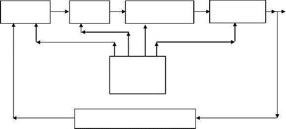
O/P
Power supply
Feedback
Fig.1 Block diagram of an inverter type-welding machine.
The system is a flexible power supply designed as current source corresponding to the block diagram shown in Fig1.which consists of the following stages.
Design analysis
Power stage: In this stage, battery supplies the oscillator, buffer, power amplifier, and transformer stage with the necessary voltage. A 48v battery is use in our design to power the circuit.
Oscillator stage: An IC SG3524 is use to generate the necessary pulse needed to drive the MOSFET (IRF150)
to alternate the DC supply. The output from the oscillator stage is amplified using transistor (9013). This
IJSER © 2015 http://www.ijser.org
International Journal of Scientific & Engineering Research, Volume 6, Issue 5, May-2015 934
ISSN 2229-5518
amplified signal triggers the metal-oxide field-effect transistor with Vgs greater the threshold voltage. The frequency at which circuit operate is determined with the oscillator stage.
Power amplifier stage: This stage determines the primary power of the transformer. MOSFET (IRF150) is used in the design for power amplification.
Transformer: This is the final stage which transforms the 48v (modified square wave) to about 25v depending on the frequency of the pulse generated at the oscillator stage.
Transformer design
Welding transformers are designed upon the nature of welding operations. For an inverter-type welding machine, the transformer is designed to be small in size and less weight compared to conventional welding machine. In an arc welding machine electric discharge is used for welding. This discharge is known as an arc.
Voltage required in maintaining the arc is given by
V = C + DL [5] ...................................................................................................................................... (1) Where; C = 15 to 20 volts
D = 2 to 3 volts
L = length of arc in mm and its value is about 2 to 4mm An arc is maintained at a voltage of about 24 to 30 volts. Design specification
Output Voltage = 25Vac
Output Current = 80A Input Voltage = 48Vdc
Transformer Power rating = 3KVA K = 0.45
F = 50Hz
BM = 1.2T
Current density, j = 3.2 A mm-2 or 3.2 x 10⁶ A/m2
Space factor Kw = 0.3
Core Dimensions
Volt per turn

Vt = K KVA [6] .......................................................................................... (2)
For square wave,
Calculation for the core area, Ai

Vt = 0.45 3 = 0.78
Vt = 4.44fBm Ai [6] ................................................................................................................................ (3)
A1 =
0.78

4.44 x 50 x 1.2
= 0.0029.28 m2 or 29.28 cm2
IJSER © 2015 http://www.ijser.org
International Journal of Scientific & Engineering Research, Volume 6, Issue 5, May-2015 935
ISSN 2229-5518
Gross iron area Ag =

Ai
0.9
3 .................................................................................................................... (4)

29.28 = 32.53 cm2
0.9
Assuming 0.9 as the stacking factor.
Width of the central limb = 2 x width of the side limb
= 2 x a.................................................................................................................................................... (5) Core depth, b = 2.5 x width of the central limb = 2.5 x 2a = 5a
Ag = b x 2a = 5a x 2a = 10a2................................................................................................................... (6)
Therefore 10 a2 = 32.53
Since a = 1.80

a = 32.53 =1.80 cm
10
b = 5 x 1.80 = 9 cm
Core depth, b = height of the yoke for shell type, Hy

Depth of the yoke Dy = width of the side limb = 1.80 cm
Window Dimensions
Aw =
KVA

2.22 x f x B x A x K x j x 10−3
[7] ......................................................................................... (7)
Aw =
3

2.22 x 50 x 1.2 x 2.928 x 10−3 x 0.3 x 3.2 x 106 x 10−3
Aw = 8.01 x 10⁻³ m2 or 80.1 cm2
Aw = window height (Hw) x window width (Ww )

HW = 3
WW
HW = 3 Ww
Aw =
3Ww
= w 2
[6] ............................................................................................................................ (8)
IJSER © 2015 http://www.ijser.org
International Journal of Scientific & Engineering Research, Volume 6, Issue 5, May-2015 936
ISSN 2229-5518
Ww =

80.1 = 5.2 cm
3
Hence, Hw = 3 x 5.2 = 15.6 cm
Overall height H = Hw + 2 ..................................................................................................................... (9)
= 15.6 + (2 x 1.80) = 19.2 cm
Overall width W = (2 x Ww ) + (4 x a) .................................................................................................. (10)
= (2 x 5.2) + (4 x 1.80) = 17.6 cm
Winding
V1

Primary winding turns T1 =
Vt
........................................................................................................... (11)

48 = 62
0.78
Total number of turns at the primary is 124 (center tapped)
Primary winding current
I1 =

Power ................................................................................................ (12)
V1

= 3000
48
= 62.5 A
Taking current of 3.2 A/mm2 for the primary, the conductor area
a1 =
62.5

3.2
= 19.53 mm2
To calculate the diameter of conductor,
a1 =πr =
πd2

4
.....................................................................................................................................(13)
Where a1 = area of primary conductor, d = conductor

d = (4 x 40)
3.142
=4.996 mm
Secondary winding turns T2 =

V2 ....................................................................................................... (14)
Vt
IJSER © 2015 http://www.ijser.org
International Journal of Scientific & Engineering Research, Volume 6, Issue 5, May-2015 937
ISSN 2229-5518
T2 =
25

0.78
= 32
While calculating secondary number of turns, allowance of 5% is selected so as to compensate for the voltage drop in the winding.
Therefore
T = 32 + 5
+ 32 = 34

2 100
Secondary winding current
I2 =

Power .............................................................................................. (15)
V2

= 3000
25
= 120 A
Taking current of 3.2 A/mm2 for the secondary, the conductor area

a = 120
= 40 mm2
2 3.2
To calculate the diameter of conductor,
a 2 =πr =
πd2

4
...................................................................... (16)
Where a2 = area of secondary conductor, d = conductor

d = (4 x 120)
3.142
= 12.4 mm
Design of an Oscillator Using IC Sg3524
RT (R8 + R9 ) and C1 connected at pin 6 and pin 7 of the IC SG3524 respectively determine the frequency of oscillation. Using equation below we determine the value of the unknown parameter.

f = 1.18
C1CT
[8] ....................................................................................................................................... (17)
Assume C1 = 0.1 x 10⁻⁶ F and the required frequency f = 50Hz
Therefore,

f = 1.18
0.1 x 10−6 x 50
= 236 KΩ
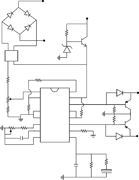
The IC SG3524 is used in the oscillation section of this inverter. This IC is used to generate the 50Hz frequency required to generate AC supply by the inverter. To start this process, battery supply is given to the pin 15 of the SG3524 through NPN transistor (TIP41). D3 at the base of Q3 as shown in Fig2. is use to regulate the IC SG3524 supply voltage. The pin 8 is connected to the negative terminal of the battery. The pins 6 and 7 of the IC are the oscillation section pins. The frequency produced by the IC depends on the value of the capacitor and resistor connected at these pins. The capacitor (0.1 µF) is connected to pin 7. This capacitor decides the 50Hz frequency output by the IC. Pin 6 is the timing resistance pin. The resistance at this pin keeps
IJSER © 2015 http://www.ijser.org
International Journal of Scientific & Engineering Research, Volume 6, Issue 5, May-2015 938
ISSN 2229-5518
the oscillator frequency constant. A preset variable resistor (20K) is connected to ground from pin 6 of the IC. This preset is used so that the value of the output frequency can be adjusted to a constant 50Hz. A fixed
resistance of 220K is connected in series with the variable resistor as shown fig3. by the relation:

F = 1.30
C1CT
[9]. ..................................................................................................................................... (18)
Where F is the frequency in KHz, RT is the total resistance at pin 6, and CT is the total capacitance at pin 7. Therefore, to obtain a frequency of 50Hz,
Given CT = 0.1µF

F = 1.30
50 x (0.1 X 10−6 )
= 260 KΩ
Therefore, RT must be varied at 100K to obtain a frequency of 50Hz. In our design, we used a fixed resistor of 200K and a variable resistor of 100K.
Signals generated at the oscillator section of the IC reach the flip-flop section of the IC. This section converts the incoming signals into signals with changing polarity. In this signal, changing polarity means when the first signal is positive, the second would be zero and when the first signal becomes zero, the second would be positive. Therefore, to achieve a frequency of 50Hz, this process most repeat every 50 times per second i.e. a pulsating signal with 50Hz frequency is generated inside the flip-flop section of the IC.
This 50Hz frequency alternating signal has an output at pins 11 and 14 of the IC.
This pulsating signal may also be known as the MOS drive signal. This MOS drive signal at pins 11 and
14 is between 4.6 - 5.4V
Voltage at these pins should be same, because any variation in the voltage at these pins could damage the
MOSFET at the output.
Since the reference voltage for the error amplifier (pin 2) is set to be 2.5v using voltage divider. Therefore voltage supplied to pin 1 said to be 2.5v.
Using voltage divider:

Assume R4 = 4700 ,
Vpin 1 = Vref x

R 4
R 4 + R 3
...........................................................................................................................(19)
Vpin 1 = 2.5 v
2.5 = 5 x
4700

4700 + R 3
R3 = 4700 or 4.7 K
IJSER © 2015 http://www.ijser.org
International Journal of Scientific & Engineering Research, Volume 6, Issue 5, May-2015 939
ISSN 2229-5518
Vpin 2 = Vout x

R s
R s + R 5
......................................................................................................................... (20)
RS = R6 + R7 , note that Vout is positive value which is equals 14.5v in our design. Required voltage at pin 2 equals 2.5v

Assume R5 = 100 K ;
R s =

Vpin2 x R s
....................................................................................................................................(21)
Vout
+ Vpin2
R s =
2.5 x 100 000

14.5 - 2.5
= 20.833KΩ


Taking preset R6 as 20k then R7 = 0.83 K
Vpin 15 = VD3 – VBE(Q3)
Vpin 15 = 13 – 0.7 = 12.3 V
Results and discussion
After the design and construction, open circuit and short circuit test were carried out. The physical working of the machine was also carried out.
The tongs of the electrode holder grip the electrode tight for different job positions; hence no arcing effect was noticed on the tong. Arc production with the different gauge of electrode was very satisfactory for the metal works.
It has good performance and high operational efficiency and test showed that the design specified the anticipated requirement when compared to the conventional arc-welding machine.
Conclusion
The design and construction of an inverter type 3KVA, 50 Hz, single-phase arc welding machine has been successfully presented in this work.
The successful completion of this work will provide job opportunities and improve the standard of living of most people in the third world countries like Nigeria. It will also reduce the dependence of third world countries on imported commodities.
List of symbols and abbreviations:
V1 = primary voltage V2 = secondary voltage Vt = turns per volts
IJSER © 2015 http://www.ijser.org
International Journal of Scientific & Engineering Research, Volume 6, Issue 5, May-2015 940
ISSN 2229-5518
I1 = primary current
I2 = secondary current
F = frequency (hertz )
U1
D4 D6
+ 48V
D7 D5
PC 123
4.7 KΩ R1
U2 D3
13V
TIP41
Q3
100 KΩ
R6
20 KΩ
1KΩ
R5
4.7 KΩ
R7
R3
4.7 KΩ
1
2
3 R4 4
5
16
15
14
13 R2
12
330Ω
10 KΩ
D1
R10
T1
9012
Q2
6
R9 100K 200 KΩ
R8 7
C1 8
0.1µF
11
10 10 KΩ
9 R14
10 KΩ
R11
D2
9012
Q2
T2
0.1µF
C2 R13
R12
47 KΩ
C3
10 KΩ
1µF, 50v
Fig2. Oscillator/ buffer stage
IJSER © 2015 http://www.ijser.org
International Journal of Scientific & Engineering Research, Volume 6, Issue 5, May-2015 941
ISSN 2229-5518
R17
Q4 1KΩ
T2 T1
R24
1KΩ
Q11
Q5
Q6
Q7
Q8
Q9
Q10
R18
1KΩ
R19
1KΩ
R20
1KΩ
R21
1KΩ
R22 48v
1KΩ
R23
R25
1KΩ
R26
1KΩ
R27
1KΩ
R28
1KΩ
R29
1KΩ
R30
Q12
Q13
Q14
Q15
Q16
Q17
1KΩ D8
D9 1KΩ
a
N1
A2 A1
Primary


Electrode/Holde
N2
U2 U1

Secondary
Work
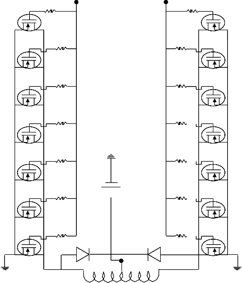
Fig3. Power amplifier/transformer stage
IJSER © 2015 http://www.ijser.org
International Journal of Scientific & Engineering Research, Volume 6, Issue 5, May-2015 942
ISSN 2229-5518
References:
[1] A. Alexander, R. Bohnart, and E Witcraft, R, The Fundamentals of Welding, Cutting, Brazing, Soldering and Surfacing of Metals, London: John Deere Publishing, pp. 234-256, 2000.
[2] A. Althouse, K. Bowditch, & Turnquist, Modern Welding. London: Goodheart-Wilcox Company, Inc. pp.456-461, 2004
[3] M.G. Say, The performance and Design of Alternating Current Machine, London: Pitman, pp.176-198,
1978
[4] B.A Ezekoye, “Characteristization and Performance of a solid state inverter and its Application in
Photovoltaic”, The Pacific journal of Science and Technology, Vol.8, no. 1, pp.68-72, May 2007.
[5] E.Lincolin, The Procedure Handbook of Arc Welding, (14th edition), New Jersey: Prentice Hall Inc., pp
1-6, 1994.
[6] K. M. Murthy Vishnu, Computer-Aided Design of Electrical Machines, Sultan Bazar: Adithya Art printers, pp.95-134, 2008.
[7] B.L Theraja and A.K. Theraja, Electrical Technology (24th edition), New Delhi: S.Chand and Company
Ltd, pp.1122-1146, 2005.
[8] R..L. Boylestad and L. Nashelsky, Power Electronics Devices and Circuit Theory, (6th edition), New
Delhi: Prentice Hall, pp.415-468.1996.
[9] M. Rasheed, Power Electronics, Circuits, Device and Application (4th edition), New Delhi: Prentice
Hall, pp. 378-388, 2013
Authors: Engr. Ovbiagele U, Engr. Obaitan B Electrical/Electronic Engineering Department Auchi Polytechnic, Auchi
E-mail: uma4hon2@yahoo.com
08062495480
IJSER © 2015 http://www.ijser.org