International Journal of Scientific & Engineering Research, Volume 5, Issue 4, April-2014 392
ISSN 2229-5518
Core Shell Carbon Nanospheres Synthesis via
Semi-Chemical Vapor Deposition Method
Ehab S.A. Mahal∗a, Faridah Sonsudinb, Shaymaa S. A. Al-Mutlaqa, Rosiyah Yahyaa
Abstract -- Carbon core shell nanospheres were synthesized using bitumen-derived coal obtained from pyrolysis of petroleum bitumen. The synthesis has been performed with the aid of iron compound as a catalyst in an atmosphere of argon at 600oC. Characterization of carbon nanospheres was carried out by field emission scanning electron microscopy, transmission electron microscopy; Raman and Fourier transform infra-red spectroscopies and thermal gravimetric analysis. The analysis of the TEM images provided simple and fast identification of thee roughness of the surfaces. The
microscopic characterization indicates the existence of core shell hollow and solid carbon nanospheres of a uniform size, and the diameter was found to be in the range of 5-50 nm. Roughness analysis result of the carbon spheres images shows less surface roughness. Thermal analysis reveals that the as-prepared carbon nanospheres have high thermal stability. Additional advantages are low cost and high availability.
![]()
∗ Corresponding author. Tel/Fax: 00-603-79677185. E-mail address: ehabmahal@yahoo.com; ehabmahal@hotmail.com (Ehab Mahal)
a) Department of Chemistry, Faculty of Science, University of Malaya, 50603, Kuala Lumpur, Malaysia
b) Chemistry Division, Centre for Foundation Studies in Science, University of Malaya, 50603, Kuala Lumpur, Malaysia
IJSER © 2014 http://www.ijser.org
International Journal of Scientific & Engineering Research, Volume 5, Issue 4, April-2014 393
ISSN 2229-5518
carbon nanospheres (CNSs), in recent decades has attracted enormous interest in the field of nanostructured carbon[1]. CNSs have great importance because they can be used in many applications, e.g., lithium-ion battery anodes due to their large specific surface-to-volume ratio, hydrogen storage, drug delivery devices, artificial cells, protectors for sensitive components, supports for catalysts, hollow spheres composites, adsorbents, lubricants and high surface activity and thermal resistance properties, etc. [2-9]. There are several reports on the preparation of carbon nanospheres from various hydrocarbons using different methods [10-13].
All methods can be divided into two parts: one is non- catalytic method, such as arc-evaporation technique, laser vaporization and electrochemical synthesis. Methods based on the chemical vapour deposition (CVD) of carbon from molecular precursors, assisted by the catalytic activity of small transition metal particles, have also been considered as the method of choice for the mass production of CNSs. Various sources of Fe have been used to generate CNSs [14-
16]. Metals that have shown the greatest promise in this regard are Fe, Co and Ni, where
The other method is supported catalytic method, which always employs transition metal (Fe, Co, Ni and Cu) as catalysts like chemical vapor deposition process (CVD). The CVD method is proved to be the most suitable one for the industrial production of carbon nano or micro structured materials. In this method, supported template is very important due to the interaction with the metal catalyst, chemically and also physically [17]. This interaction will disperse the metal catalyst, formed in the CVD process, which in turn, decides the configuration of the metal and its chemical character. In addition to the previous methods, there is an increased interest in pyrolysis, hydrothermal treatment and other techniques [18-21].
Bitumen is a carbon-rich by-product of petroleum industry [22]. Due to this property and its availability, the use of bitumen and like materials for preparation of carbon nanoparticles has been a subject of considerable attention [11, 23].
This study reports the synthesis of carbon nanospheres using a bitumen-derived coal (obtained from the pyrolysis of petroleum bitumen) as a carbon source in the presence of Ferric chloride as catalyst precursor in an atmosphere of argon gas. The synthesized carbon spheres were randomly oriented and a little tangled with each other were noticed also.
Petroleum bitumen was supplied by Petronas Malaysia. Specifications of bitumen are shown in Table1. Anhydrous iron (III) chloride, (98%, J. Kollin Chemicals) has been chosen as a catalyst; ASTM Sieve Stack, mesh no. 45μm and electrical mechanical shaker (Heidolph Promax 2020) used for sieving the bituminous coal. Alumina boat of size 10 cm3 has been used as substrate. Purified Argon gas (99%, Argon Mox-Linde gases Sdn Bhd) was used as an inert gas carrier.
Penetration (25oC,100gm, 0.1mm) | Softening point (oC) | Ductility (25oC, cm) | Solubility in T.C.E. (%) | Loss of heat | Drop by heat (%) | Specific gravity |
80-100 | 50 | +100 | 99.5 | 0.2 | 20 | 1.0205 |
Bituminous coal was prepared by pyrolysing petroleum bitumen. The resulted coal has been crushed and sieved using ASTM Sieve Stack, mesh no. 45μm and mechanically shaken for about 12 hours using electrical mechanical shaker (Heidolph Promax 2020). The collected sieved carbon has been kept in a dry glass container with screw cap to prevent moisturizing.
Bitumen based coal was weighed, placed and spread out in the bottom of a small alumina boat as a thin layer (0.05-0.1) mm. Ferric chloride was spread out over the coal layer. The boat was loaded into a quartz tube (20 mm i. d. and 1000 mm long), which was mounted in a horizontal tube furnace. The boat, placed in the central reaction zone of the quartz tube, was run at rate 5oC/ min from ambient temperature until 600oC and maintained for a while in argon atmosphere. The temperature then was ramped and at 800oC the quartz tube was left to cool naturally to room temperature. The yield of product was about 60%.
Scanning electron microscopy images were obtained using a high-resolution field emission scanning electron microscope (FESEM) from two branded machines, namely JEOL FESEM JSM- 7500F and Philips XL40 FEG FESEM while transmission electron microscopy (TEM) images were recorded on a LEO-Libra 120 TEM microscope operated at
120 kV. Samples for TEM were dispersed in acetone and the
IJSER © 2014 http://www.ijser.org
International Journal of Scientific & Engineering Research, Volume 5, Issue 4, April-2014 394
ISSN 2229-5518
suspensions were dropped on a holey carbon coated copper grid.
Three Dimension (3D) images has been generated depends on TEM images using computer software, leading to further demonstration of the CNSs. The measurement of roughness and surface area are involved in this study also.
Raman spectra were recorded on a Perkin-Elmer Raman Micro 200 dispersive Raman spectrometer equipped with an Olympus® BX51 reflected illumination frame microscope and a charge-coupled detector. The excitation wavelength was 785 nm, 350 mW. The spectra for CNSs sample was recorded at a spectral aperture of 10 μm, 4 scans, and a resolution of 3.0 cm−1. Fourier transform infra- red spectroscopy (FT-IR) spectra were obtained using a Perkin-Elmer Spectrum 400 FT-IR / FT-NIR spectrometer. The spectra for CNSs sample was recorded at 4 scans and resolution of 4 cm−1. Roughness analysis has been applied on the TEM image in order to demonstrate the morphologies of the as prepared spheres which are sensitive to the future application for thin films purposes. Thermo-gravimetric analysis (TGA) for the as-prepared CNSs was recorded using Thermo-gravimetric Analyzer Perkin-Elmer TGA 4000 using an inner nitrogen flow of 20 cm3 per minute and at a heating rate of 20°C/min.
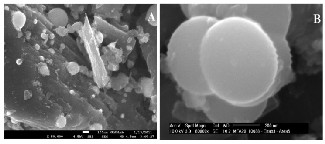
The FESEM micrographs in Figure 1, of the as-prepared CNSs, grown on alumina boat using ferric chloride catalyst were observed. The image A is the photo of CNSs observed at magnification of 50000x, B has observed at 80000x magnification. FESEM observations of the as-prepared sample indicated the presence of CNSs, as shown in Fig.1. (A) and (B). Apparently, the major product former corresponds to CNSs containing large number of smaller carbon nanospheres with an average diameter of 2-50 nm and fewer carbon nanospheres with average diameter of about 200-400 nm in the product.
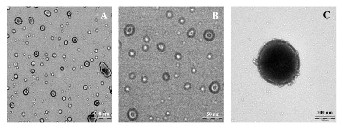
Fig.2. (a), (b) and (c) Show typical TEM images of the as- prepared sample. Large quantities of carbon nanospheres with a proportion of not less than 85% and with diameters in the range of 2–30 nm were obtained. These CNSs include core shell hollow spheres (external diameter: 5–50 nm; shell thickness: 0.3–2 nm) and solid spheres (diameter: 5–30 nm). Solid spheres with larger diameter (200-400 nm) are also noticed.
Evaluation of the diameters of carbon spheres by TEM agreed with the heights results obtained from the roughness analysis of the 3-dimension image of 3-A TEM image generated by using computer software. Several parameters, such as root mean square (RMS), mean roughness (Ra), height of particle (Rmax), surface area and surface area different between two dimensional image and three-dimensional image, as can be seen in Table 2.
Parameters | Ra (nm) | RMS (nm) | Rmax (nm) | S (μm2) | Sds (%) |
Roughness | 4.52 | 7.086 | 43.85 | 2.767 | 5.66 |
IJSER © 2014 http://www.ijser.org
International Journal of Scientific & Engineering Research, Volume 5, Issue 4, April-2014 395
ISSN 2229-5518
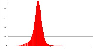
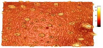
Fig.3. shows 3-dimension image of carbon spheres generated from computer software. It can be seen that most of the spheres are of hollow type and there is also few solid spheres scattered among them. It is obvious that is the image surface is composed of relatively large interconnected particles and pores, building up high “mountains” and deep “valleys”, forming a rather flat but more complex surface texture which is consistent with a much less rough topography.
Fig.4. Shows 3-dimension images of hollow and solid spheres generated from the software at 20, 200nm respectively. (4-a`) shows magnified TEM image of carbon hollow sphere and its 3D image. The 3D image shows solid center of around 14nm in diameter and one shell of around
2.5 nm while the external diameter of the sphere was
around 25nm; all measurements obtained from TEM. The (4-b) image is a 3D generated image of (2-C) TEM image. The image looks like hollow sphere with fully filled center. It is obvious that the center is solid and fills all the area between the center and the shell. We propose that this happened because of the further fusion and deposition during the synthesis at high temperature (800oC).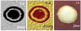
Fig.5. shows that all synthesized samples had surfaces with irregularities of quite small height. The height distribution histogram is nearly sharp and the maximum of height distribution displays a sharp tip. This is can be reflected in the RMS roughness values (the standard deviation of the Z values, Z being the total height range analyzed) of the image. Therefore it can be concluded that the sharper the size distribution is, the rougher the resulting image and vice versa. This can be good found as it demonstrates that the film prepared from using these carbon nanospheres will be of high homogeneity surface and less roughness which give these CNSs for potential for lubricating application.
The Raman spectrum (Fig. 6) of the sample shows two broad peaks centered at about 1308 and 1588 cm-1, which are associated with the vibrations of carbon atoms with dangling bonds for the in-plane terminations of disordered graphite and the vibrations in all sp2 bonded carbon atoms in a 2-dimensional hexagonal lattice, respectively The intensity ratio of D to G band (ID/IG) is calculated to be
1.205, further reflecting the relative disorder and low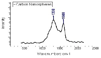
graphitic crystallinity of the CSs. The size of the carbon nanospheres was calculated and found to be around 53.02 nm. This agrees in a part with the results from [24, 25].
FTIR spectrum (Fig.7.) further confirms the chemical of the CNSs where a strong peak at 1643 cm-1 is attributed to C=C group and the two peaks at 2863 and 2919 cm-1 belonging to the C–H groups are observed. This is in agreement with other results [24, 26].
The TGA curve of the CNSs is presented in Fig.8. There is almost no drastic loss of weight in the sample in the temperature range of 100–300oC.
IJSER © 2014 http://www.ijser.org
International Journal of Scientific & Engineering Research, Volume 5, Issue 4, April-2014 396
ISSN 2229-5518
Nevertheless, a rapid weight loss of carbon nanospheres is observed in the temperature range of 540-670oC. The weight loss of the TGA curves does not reach zero even at 900oC, further revealing the possible existence of trace amount of Fe in the final products. Based on this result, the CNSs possess high thermal stability. In addition, there was peak at about 506oC in the DTG curve indicating the sample decomposed rapidly at this temperature.
Therefore, these as-obtained carbon nanospheres may have promising applications as catalyst supports and lubricating materials as mentioned in other studies [27-30].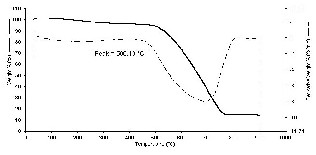
We have proposed a mechanism for the formation of the carbon spheres depends on graphitic layer self-assembly growth mechanism [31] which is seems most suitable to illustrate the growth of carbon spheres. Firstly, the char convert into active carbon (gaseous carbon mostly Cn H m , CH4 , CO) and the Fe atoms from the pyrolysis of ferric chloride were clustered into active Fe nanoparticles (Fig.9).
The active carbon can react with each other to produce hexagonal lattice that is composed of sp2-bonded carbon,
namely graphite sheets. The observation of graphite sheets in the sample proved this found. The graphite sheet de- composed into carbon atoms and precipitated on the surface of Fe nanoparticles to form small carbon fragments around the encapsulated α-Fe. The structural defects, especially the dangling bonds at the edges of the carbon fragments, promoted the assembling and rearranging of these fragments, resulting in layered structure on the surface of α-Fe nanoparticles Fig.9.
The formation of a solid carbon sphere may correlate with the nucleation of a carbon ring followed by a spiral shell growth, which has been proposed to explain the formation mechanism of solid carbon spheres [32]. The formation of the spiral shell growth needs energy more than that of the carbon hollow capsules. So, when the temperature was increased to 800oC the solid spheres have been formed. The whole process can be schematically described in Fig.9.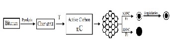
Carbon core shell hollow and solid nanospheres was successfully synthesized from, petroleum bitumen based coal obtained from the pyrolysis of bitumen as a source of carbon at multi-level temperature. This method produces high yield of carbon hollow nanospheres and fewer of solid spheres. These spheres have diameters in the range of 5–50 nm and good thermal stability. The applied method provide an alternative source for production of carbon nanomaterials.
The authors gratefully acknowledge the financial support and sponsoring through the programs of Postgraduate Research Fund (PPP), and Research Grants, provided by the University of Malaya under grant number PS327/2008C, grant number PS141/2007B and grant of Project No. RG183/11AFR. The authors express their sincere gratitude to Dr. Ahmed Mahal at Pharmazeutisches Institut- Bonn, Germany for his helpful discussion and suggestions during the FTIR interpretation. The authors also acknowledge Mrs.
IJSER © 2014 http://www.ijser.org
International Journal of Scientific & Engineering Research, Volume 5, Issue 4, April-2014 397
ISSN 2229-5518
Zubaidah Abu Hassan and Mrs. Rosemawati Hashim from the EM unit-Faculty of Medicine, University of Malaya for their help to perform the TEM characterization. The authors are also grateful to Mrs. Nor Aishah Osman and Mr. Mohammad Faizal Zakaria from Failure analysis lab at MIMOS Berhad, Malaysia for their assistance to perform FESEM characterization.
[1] Xie Y., Huang Q., Huang B. (2009). Preparation of high purity carbon nanospheres by the chemical reaction of calcium carbide and oxalic acid, Carbon; 4 7: 2292-2295.
[2] Jaroniec Z. Li, M., Papakonstantinou P., Tobin J.M., Vohrer U., Kumar S., et al. (2007). Supercritical Fluid Growth of Porous Carbon Nanocages , Chem. Mater; 19:
3349.
[3] Schaper A.K., Hou H., Greiner A., Schneider R., Phillipp F. (2004). Copper nanoparticles encapsulated in multi-shell carbon cages, Appl. Phys. A; 78(1): 73-77.
[4] Kobayashi T., Sekine T., He H. (2003). Formation of
Carbon Onion from Heavily Shocked SiC, Chem. Mater.;
15: 2681.
[5] de Heer W.A., Poncharal P., Berger C., Song J. Gezo, Z.,
Bettini J., et al. (2005). Liquid Carbon, Carbon-Glass Beads
and the Crystallization of Carbon Nanotubes, Science; 307:
907-910.
[6] Shang N.G., Staedler T., Jiang X. (2006). Radial textured carbon nanoflake spherules , Appl. Phys. Lett.; 89: 103112. [7] Dai D.-J., Chan D.-S., Wu H.-S. (2012). Modified Carbon Nanoball on Electrode Surface Using Plasma in Enzyme- Based Biofuel Cells, Energy Procedia 14, 1804 – 1810 [8]Baumeister E., Klaeger S. (2003). Advanced New Lightweight Materials: Hollow-Sphere Composites (HSCs) for Mechanical Engineering Applications, Adv Eng Mater 5,
9:673-677.
[9] Lee, KT; Jung, YS; Oh, SM, (2003). Synthesis of tin-
encapsulated spherical hollow carbon for anode material in lithium secondary batteries, J Am Chem Soc, 125, 19, 5652-
5653.
[10] Gornostayev S.S., Harkki J.J. , Kerkkonen O., Fabritius
T.M.J., Carbon spheres in metallurgical coke , Carbon 2010 ;
48: 4200 –4203.
[11] Liu X., Yang Y., Liu H., Zhang W.J.C., Xu B. (2007).
Carbon nanotubes from catalytic pyrolysis of deoiled
asphalt, Mater. Lett.; 61: 3916–3919.
[12] Gorelik T., Urban S., Falk F., Kaiser U., Glatzel U.,
(2003). Carbon onions produced by laser irradiation of amorphous silicon carbide, Chem. Phys. Lett.; 373: 642–645. [13] Xua Z.X., Lin J.D., Roy V.A.L., Oua Y., Liao D.W., (2005). Catalytic synthesis of carbon nanotubes and carbon
spheres using Kaolin supported catalyst, J. Mater. Sci. Eng. B; 123: 102–106.
[14] Govindaraj A, Sen R, Nagaraju BV, Rao CNR (1997). Carbon nanospheres and tubules obtained by the pyrolysis of hydrocarbons, Philos Mag Lett; 76 (5): 363–7. [15] Zhong Z, Chen H, Tang S, Ding J, Lin J, Tan KL (2000) Catalytic growth of carbon nanoballs with and without cobalt encapsulation. Chem Phys Lett; 330: 41–6. [16] Serp P, Feurer R, Kihm Y, Kalck P, Farina JL, Figueiredo IL (2001). Novel carbon supported material: highly dispersed platinum particles on carbon nanospheres. J Mater Chem; 11: 1980–1.
[17] Vander Wal R.L., Ticich T.M., Curtis V.E. (2001). Substrate–support interactions in metal-catalyzed carbon nanofiber growth, Carbon; 39: 2277–2289.
[18] Jin Y.Z., Gao C., Hsu W.K., Zhu Y.Q., Huczko A.,
Bystrzejewski M.,et al. (2005). Large-scale synthesis and
characterization of carbon spheres prepared by direct pyrolysis of hydrocarbons, Carbon, 43, pp.1944-53.
[19] Wang Q., Cao F.Y., Chen Q.W., Chen C. (2005) Preparation of carbon microspheres by hydrothermal treatment of methylcellulose sol, Mater Lett, 59, pp.3738-41. [20] Yan Y., Yang H.F., Zhang F.Q., Tu B., Zhao D.Y. (2007). Low-temperature solution synthesis of carbon nanoparticles, onions, and nanoropes by the assembly of aromatic molecules, Carbon, 45, pp.2209-16.
[21] He C., Zhao N., (2011). Production of Carbon Onions,
in: Sattler K. D., Handbook of Nanophysics - Clusters and
Fullerenes, Taylor and Francis Group, LLC.
[22] Parkash S., Petroleum Fuels Manufacturing Handbook, McGraw-Hill Companies, Inc., 2010: 101-104.
[23] Kidena K., Kamiyama Y., Nomura M. (2008). A
possibility of the production of carbon nanotubes from heavy hydrocarbons, Fuel Process. Technol., 89: 449 – 454. [24] Yang X., Li C., Wang W., Yang B., Zhang S., Qian Y. (2004). A chemical route from PTFE to amorphous carbon nanospheres in supercritical water, Chem. Commun; 3:
342–3.
[25] Jawhari T, Roid A, Casado J. (1995). Raman
Spectroscopic Characterization of Some Commercially
Available Carbon Black Materials, Carbon; 33: 1561–5.
[26] Deshmukh A.A., Mhlanga S.D., Coville N.J. (2010). Carbon spheres, J. Mater. Sci. Eng. R; 70: 1-28.
[27] Auer E., Freund A., Pietsch J., Tacke T. (1998). Carbons
as supports for industrial precious metal catalysts, Appl. Catal. A; 173: 259-271.
[28] Sun L., Cao M., Hu C. (2010). Synthesis and magnetic properties of hollow α-FeR2ROR3R nanospheres templated by carbon nanospheres, Solid State Sci., 12: 2020-2023.
[29] Zhi-Wei He, Qiu-Feng Lü, Qilang Lin, (2013). Fabrication, characterization and application of nitrogen- containing carbon nanospheres obtained by pyrolysis of
IJSER © 2014 http://www.ijser.org
International Journal of Scientific & Engineering Research, Volume 5, Issue 4, April-2014 398
ISSN 2229-5518
lignosulfonate/poly(2-ethylaniline),Bioresource Technology
127, 66–71.
[30] Qiu-Feng Lü∗, Zhi-Wei He, Jia-Yin Zhang, Qilang Lin
(2011). Preparation and properties of nitrogen-containing
hollow carbon nanospheres by pyrolysis of polyaniline– lignosulfonate composites, Journal of Analytical and Applied Pyrolysis, 92, 152–157.
[31] Bing-she X., Prospects and research progress in nano onion-like fullerenes, New Carbon Materials, 2008, 23(4):
289–301.
[32] Wang Z. L., Kang Z. C. (1997). Graphitic structure and
surface chemical activity of nanosize carbon spheres,
Carbon, 35 (3): 419-426.
IJSER © 2014 http://www.ijser.org