International Journal of Scientific & Engineering Research, Volume 5, Issue 4, April-2014 1329
ISSN 2229-5518
Control System Design to Automate 100KV Impulse Generator
Talha Iqbal, Hasan Ul Banna
Abstract— This paper is basically the practical study of converting manually operated impulse generator to automatic generator. Ever since 1970 (when the High voltage lab of UET Lahore, Pakistan was constructed) most of the equipment in this lab has been operated manually. In this Lab, we have two impulse generators with capability of 100 and 500 kilo volts which are used for testing purposes. Both of these use the same mechanism for Impulse generation. In this paper a design is proposed to automate the whole working of the Impulse generator (100KV) for which we used Arduino Board which is coded such that the operator has to insert desired impulse voltage through the computer and the rest of the process will be done by the system itself. W e used LabView Simulation tool for coding purpose. All coding is in graphical coding environment.
Index Terms—Arduino Mega 2560, Capacitor Charging, Capacitor Discharging, Impulse Generator, Impulse Application, Sphere Gap
Measurement, Sphere Gap Adjustment, Stepper Motor Control.
—————————— ——————————
1 INTRODUCTION
N Impulse generator is an electrical apparatus which produces very short duration high-voltage or high- current surges. Impulse is a signal of very high magnitude and very small duration. This impulse is passed through the trans- former for the insulation testing. Impulse voltage generation is
a two phase process:
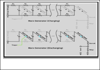
1. Parallel charging of the capacitors
2. Series discharging of these capacitors
A number of capacitors are charged in parallel to a given volt- age V and then connected in series by spark gap switches, ide- ally producing a voltage of V multiplied by the number, n, of capacitors. Due to various practical constraints, the output voltage is somewhat less than n× V. Charging and Discharging of Marx Generator is shown in Fig 1.
In control systems engineering, a system is actually a group of objects or elements capable of performing individual tasks. They are connected in a specific sequence to perform a specific function. A system is of two types:
1. Open loop system
2. Closed loop system
Both systems have their advantages and disadvantages. Open loop system is simpler, cheaper and can be easily constructed but less accurate, less reliable and can’t remove the effects of disturbances. While a closed loop system is more accurate and it can respond to disturbances but more expensive and diffi- cult to construct.
2 COMPONENTS OF IMPULSE GENERATOR
2.1 Autotransformer
An autotransformer has a single winding with two end terminals, and one or more terminals at inter- mediate tap points, or a transformer in which the primary and secondary coils have part or all of their turns in common. The primary voltage is applied across two of the terminals
and the secondary voltage (taken
from two terminals) always has one
Fig.2 Autotransformer
Fig.1 Charging and Discharging of Capacitors
————————————————
• Talha Iqbal is going to start masters degree program in industrial and control systems engineering in Sultan Qaboos University, Oman, after working as management trainee officer in a multinational organization, PH-00923314100753. E-mail: talha965@gmail.com
• Hasan Ul Banna is currently pursuing masters degree program in electric power engineering in Brandenberg Technical University, Germany, PH-
00923314176458. E-mail:majorhasan_209@yahoo.com
terminal in common with the primary voltage. The primary and secondary circuits therefore have a number of windings turns in common. Since the volts-per-turn is the same in both windings, each develops a voltage in proportion to its number of turns. In an autotransformer, part of the current flows di- rectly from the input to the output and only part is transferred inductively, allowing a smaller, lighter, cheaper core to be used as well as requiring only a single winding. I am using 5KVA variable voltage transformer which takes input 230VAC and
IJSER © 2014 http://www.ijser.org
International Journal of Scientific & Engineering Research, Volume 5, Issue 4, April-2014 1330
ISSN 2229-5518
provides a range of output i.e. 0V-200V depending upon the magnitude required for the impulse.
2.2 Power Transformer

A power transformer is a static electrical device that transfers energy by inductive coupling between its winding circuits. A varying current in the primary winding creates a varying magnetic flux in the trans- former’s core and thus a varying magnetic flux through the secondary winding. This
3 PROPOSED MODIFICATIONS
The main idea of this project is to automate this impulse gen- erator. Following are the steps in sequence:
1. Adjust the sphere gaps between capacitors according to the user input provided through pc.
2. According to impulse level requirement, DC gear mo- tor will set the voltage level by connecting feedback controlled Autotransformer through magnetic contac- tor.
varying magnetic flux induces a varying electromotive force (emf) in the secondary
Fig.3 Power
Transformer
3. After charging of capacitors, Arduino Board will dis-
connect the autotransformer by opening magnetic
winding. It is a step up (1:500) 10KVA transformer with a pri- mary, secondary and a tertiary winding (for measurement purpose). For example if 35V is applied at its primary winding then 17.5KV will be the voltage at its secondary winding. This way we get a high ac voltage. It should be noted here that the secondary current rating of this transformer is very low.
2.3 Selenium Rectifier

A selenium rectifier is a type of metal recti- fier, invented in 1933. They were used to replace vacuum tube rectifiers in power supplies for electronic equipment, and in high current battery charger applications. Vacuum tube rectifiers had efficiencies of only 60% compared to the 85% of selenium rectifiers, partially because vacuum tube
contactor and command it to rotate back to initial po-
sition (0 volts) and fire the Trigatron to discharge the
capacitors across testing object.
4. Lastly, stepper motor set back the sphere gap to initial
position to eliminate the residual charge in capacitors.
As shown in Fig 6:
rectifiers required heating. Selenium rectifi- ers have no warm-up time unlike high vac-
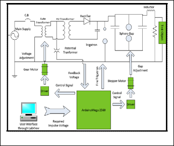
Fig.4 Seleni-
um Rectifier
uum rectifiers. Selenium rectifiers were also cheaper and sim- pler to specify and install than vacuum tubes. However they were later replaced by silicon diodes with high efficiencies (close to 100% at high voltages). Selenium rectifiers had the capability to act as current limiters which can temporarily pro- tect the rectifier during a short circuit and provide stable cur- rent. The high voltage produced by the main transformer is converted into DC voltage so that it may be used for the charging of capacitors in the impulse generator connected ahead.
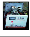
2.4 100KV Impulse Generator

The impulse gen- erator that we have in UET La-
Fig.6 Functional Block Diagram of the Process
4 ARDUINO MEGA 2560

In order to understand Arduino one must have a sound knowledge of pro- grammable logics and basic knowledge of the tactics used for such
hore is a single stage 100KV Im- pulse generator on
kind of control. Whenever intelligent
systems are involved we must clearly
know the “Microprocessors” are in-
Fig.7 Arduino Mega
2560
which I will be doing my experi- ment. From now onwards I will implement all my research and mod- ifications on this Impulse generator.
Fig.5 100KV Impulse Generator
volved. In the 21st century everyone is aware of them as it
would not be wrong to say that they are the “Digital Brains” of
any system involving them. For example take my Impulse
generator, currently everything is being done by specialized
personnel with great care especially during charging the ca-
pacitors up to a very high voltage. I can teach it to the micro-
computers just once and do the same work with great ease in
the future.
4.1 Why Arduino Mega Board?
Microprocessor is only the brain and we need some non-
IJSER © 2014 http://www.ijser.org
International Journal of Scientific & Engineering Research, Volume 5, Issue 4, April-2014 1331

ISSN 2229-5518
intelligent devices which “do as instructed” by the processor. Here is when peripherals come in, so the first option we get to use is a microcontroller which comes with many peripherals e.g. ADC, Serial Communication etc. but still these were not enough for me so I moved onto Arduino board which is a complete package with built in code burning facility.
4.2 Overview
The Arduino Mega 2560 is a complete package based on the ATmega2560 controller. Its salient features are as follows:
1. It has 54 digital input/output pins (out of which 15 pins can be used as PWM outputs)
2. 16 pins can be used analog inputs (Integrated ADCs are connected to them)
3. 4 UARTs (Hardware serial communication ports)
4. 16 MHz crystal oscillator
5. Built in USB communication support
6. Power jack for external supply in case if it is a standalone system
7. ICSP header and a reset button
8. Stronger RESET circuit
9. Atmega 16U2
4.3 LabView Interface for Arduino
The LabView Interface for Arduino (LIFA) allows users to con- trol sensors and acquire data through Arduino using the graphical programming environment of LabView. LIFA uses open source Arduino firmware to communicate with LabView. LIFA provides a simple yet powerful API for Digital IO, Ana- log Input, SPI, I2C, PWM and much more. Following are some of the basic features of LIFA.
• Analog Input (Read an individual Analog Input Pin,
Read the full Analog Input Port)
• Digital Input and Output Read or write (an individual
Digital Pin Read or write the full Digital Port)
• Pulse Width Modulation (Write an individual PWM Pin, Write the entire PWM Port)
• Built In Sensor Support
• Stepper Motors Control (up to 7 stepper motors, fully configurable step and direction control)
nals.
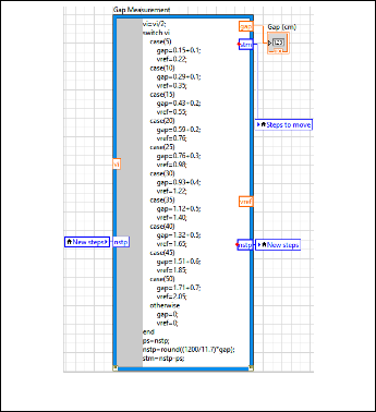
5.1 Gap Measurement
The sphere gap mechanism is simple and easy to operate. The breakdown voltage of air is 33kV/cm at standard temperature and pressure conditions (ignoring effect of humidity). I used standard values of distance for different ranges of voltage. TABLE 1 gives the values of distances between spheres for different breakdown voltages.
TABLE 1
IMPULSE VOLTAGES VS SPHERE GAP RE- QUIRED
Voltage (KV) | Gap (cm) |
5 | 0.1437 |
10 | 0.2874 |
15 | 0.4310 |
20 | 0.5890 |
25 | 0.7603 |
30 | 0.9315 |
35 | 1.1181 |
40 | 1.3150 |
45 | 1.5117 |
50 | 1.7070 |
5.2 LabView Code for Sphere Gap Measurement
The code segment for sphere gap measurement is shown be- low in Fig.8:
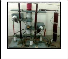
5 SPHERE GAP ADJUSTMENT
A sphere gap consists of two spherical electrodes separated by a gas-filled insulating interval. Sphere Gaps are used in Im- pulse Generator to apply the high voltage impulse by connect- ing the charged capacitors in series. In a single stage Marx Impulse Generator, two capacitors are charged in parallel to a desired voltage value. To retain this charge, a sphere gap is used which acts as a switch. When the breakdown occurs then these parallel capacitors are connected in series which makes the voltage at the output terminals twice of the input charging voltage of the capacitors. It is important to adjust the gap be- tween the spheres so that when the Trigatron is fired then for sure breakdown of the gap occurs to apply the impulse volt- age on the testing equipment connected at the output termi-
IJSER © 2014 http://www.ijser.org
Fig.8 Code Segement for Sphere Gap Measurement
International Journal of Scientific & Engineering Research, Volume 5, Issue 4, April-2014 1332
ISSN 2229-5518
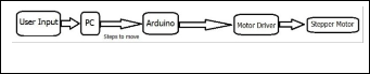
5.3 Algorithm for Sphere Gap Adjustment
The Basic algorithm for the adjustment of distance between sphere gaps is as follows:
• User inputs the required impulse voltage into the
main computer.
• The main computer sends a signal to Arduino via
USB according to the received value of voltage.
• Arduino compares the value of voltage entered with that of distance for the specified range.
• By deciding the distance required between sphere
gaps Arduino generates a signal for stepper motor (connected mechanically with the spheres) which per- forms calculated rotation adjusting the distance to specified value.
• This distance is kept during the whole charging pro-
cess and after discharging the stepper moves back to initial position joining both the spheres to ground level.
These steps are shown in block diagram below:
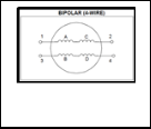
gap distance. Its schematic diagram is shown in the Fig 11. Unlike unipolar motors, bipolar motors have no center taps. The advantage to not having center taps is that current runs through an entire winding at a time instead of just half of the winding. As a result, bipolar motors produce more torque than unipolar motors of the same size. Bipolar motors have approximately 30% more torque than an equivalent unipolar motor of the same volume.
5.5 Drive Circuit
Bipolar stepper motors do not have the center tap. That makes the motor construction easier, but it needs a different type of driver circuit which is called an H-bridge because it resembles a letter ‘H’. The current can be reversed through the coil by closing the appropriate switches. A bipolar drive circuit is shown in Fig 12.
Fig.9 Block Diagram for Sphere Gap Adjustment
5.4 Stepper Motor
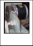
A stepper motor, as its name suggests, moves one step at a time, unlike those conventional motors, which spin con- tinuously. Stepping motors fill a unique niche in the motor control world. These motors are commonly used in meas- urement and control applications. We used stepper motor because we com-
Fig.12 Dual H-Bridge Drive Circuit
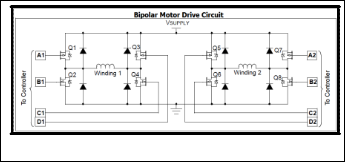
After that we need a sequencer to issue proper signals in a required sequence to the H-bridges. Two H-bridges are used to control two windings of the stepper motors as shown in the Fig 12.
5.6 LabView Code for Sphere Gap Adjustment
The code segment for Stepper motor control is shown below in
Fig.13:
mand a stepper motor to move some specific number of steps, it rotates in- crementally that many number of steps
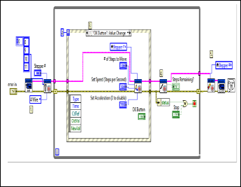
Fig.10 Stepper
Motor Used
and stops. Because of this basic nature of a stepper motor, it is widely used in low cost, open loop position control systems. Open loop control means no feedback information about the position is needed. This eliminates the need for expensive sensing and feedback devices, such as optical encoders. Motor position is known simply by keeping track of the number of input step pulses.
It has following advantages:
• Brushless
• Load Independent
• Open Loop Positioning
• Holding Torque
• Excellent response
Fig.11 Bipolar Stepper
Motor
Fig.13 Code Segement for Stepper Motor Control
The two common types of stepper motors are the bipolar mo- tor and the unipolar motor. The bipolar and unipolar motors are similar, except that the unipolar has a center tap on each winding. I used a two phase four wire bipolar stepper motor in my project because I needed high torque in adjusting sphere
6 CHARGING OF IMPULSE GENERATOR
Let’s have a look at the details of each and every device in- volved during this operation.
IJSER © 2014 http://www.ijser.org
International Journal of Scientific & Engineering Research, Volume 5, Issue 4, April-2014 1333
ISSN 2229-5518
6.1 Auto Transformer
It is the main part of charging phase. An autotransformer is an electrical transformer with only one winding. In an autotrans- former portions of the same winding act as both the primary and secondary. The winding has at least three taps where elec- trical connections are made. An autotransformer can be small- er, lighter and cheaper than a standard dual-winding trans- former however the autotransformer does not provide electri- cal isolation.
In my project I have used an autotransformer of 5 KVA with winding having current rating of 15A.
6.2 Potential Transformer
Potential Transformer is used in electrical power system to step down the voltage to a safe value which can be fed to low ratings meters and relays. Commercially available relays and meters used for protection and metering, are designed for low voltage. PT theory is just like theory of general purpose step down transformer. Primary of this transformer is connected across the phases or ground depending upon the requirement. The input voltage is applied across the terminals of primary winding of that transformer, and then proportionate second- ary voltage appears across the secondary terminals of the PT. In an ideal PT, when rated burden connected across the sec- ondary the ratio of primary and secondary voltages of trans- former is equal to the turn ratio and the two terminal voltages are in precise phase opposite to each other. But in actual trans- former there must be an error in the voltage ratio as well as in the phase angle between primary and secondary voltages.
We used 220/9 voltage ratio potential transformer in the feed- back loop to get feedback voltage from the autotransformer to accurately adjust the charging voltage.
6.3 Relay
A relay is an electrically operated switch. Many relays use an electromagnet to operate a switching mechanism mechanical- ly, but other operating principles are also used. Relays are used where it is necessary to control a circuit by a low-power signal (with complete electrical isolation between control and controlled circuits), or where several circuits must be con- trolled by one signal. We used two relays in my circuit:
1. For opening the charging circuit when the capacitors
are charged to the desired value. It is a 30A 12V dc re- lay.
2. To fire the Trigatron when required. Its rating is 9A
12V dc.
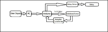
6.4 Algorithm for Charging Process
The Basic algorithm for the charge control unit of IG is de- scribed below:
• User inputs the required impulse voltage into the main computer.
• The main computer sends a signal to Arduino via
USB according to the input.
• Arduino (after adjusting sphere gap) starts moving the autotransformer in order to increase the voltage on the primary of HV Transformer.
• It continuously takes feedback of the voltage in order
to make sure that the capacitors are charged to de- sired voltage.
• Upon reaching the specified value of voltage, it is cut
off from the circuit (after a short delay due to charg- ing time constant) by sending a command signal to
12V dc relay.
• After this process the IG is ready to provide us the
desired Impulse when Trigatron is fired.
Its functional block diagram is shown below:
6.5 LabView Code for Capacitor Charging
Fig.14 Block Diagram for Charging
The code segment for capacitor charging is shown below in
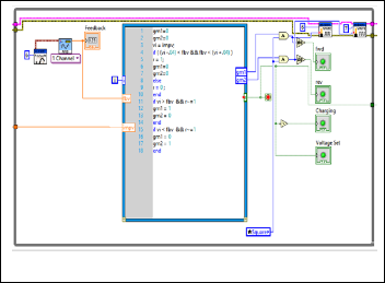
Fig.15:
Fig.15 Code Segment for Charging
7 IMPULSE APPLICATION AND DISCHARGING
After charging the capacitors and disconnecting the auto transformer from generator, we are ready to apply the impulse on the testing equipment. Impulse is applied by using a Tri- gatron. When Trigatron is fired, double voltage appears across the sphere gap which causes its breakdown. This breakdown brings the charged capacitor is series and impulse is applied on the equipment.
After application of impulse it is necessary to discharge the
IJSER © 2014 http://www.ijser.org
International Journal of Scientific & Engineering Research, Volume 5, Issue 4, April-2014 1334
ISSN 2229-5518
capacitor to eliminate the residual charge present in the cir- cuit. For this purpose grounding of the capacitors is required. To achieve this goal, spheres are joined together by using stepper motor already present in the control circuit. After join- ing them together we have to fire the Trigatron again to ground the capacitors to eliminate the residual charge.
7.1 LabView Code for Impulse Application and
Discharging
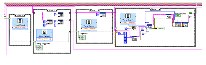
LabView code to apply the impulse and discharge the circuit is shown below in Fig.16:
Fig.16 Code Segment for Impulse Application and Discharging
8 USER INTERFACE WINDOW
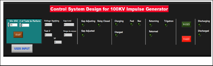
Fig.17 shows the user interface window on Labview software where he can enter the input and observe the whole process completing its stages step by step. Each stage of the process has its corresponding LED on the user interface window to know the current stage of the impulse generator.
Fig.17 User Interface W indow
IJSER © 2014 http://www.ijser.org
International Journal of Scientific & Engineering Research, Volume 5, Issue 4, April-2014 1335
ISSN 2229-5518
8 CONCLUSSIONS
Computerized control systems have significantly improved operations of systems over the last ten years. In the scope of industrialization, automation is a step beyond mechaniza- tion. Automation greatly decreases the need for human senso- ry and mental requirements while increasing load capacity, speed, and repeatability. Now this automated impulse genera- tor has achieved
• Speed
• Repetition
• Efficiency
• Human safety
• Adaptability
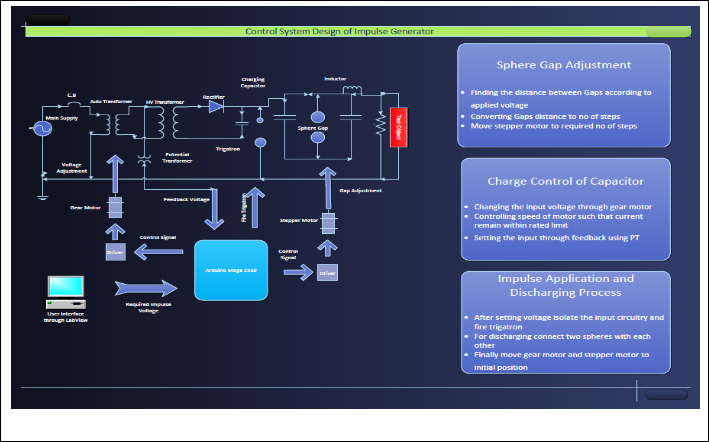
The summary of the complete control system is shown below in Fig 18.
In concluding lines we must say that we are really delightful
to implement such task for our University’s High Voltage lab.
It will really help the upcoming sessions in doing their lab
tasks and will motivate them to do such projects in near future
which are beneficial to them and the University.
ACKNOWLEDGMENT
We wish to thank all teachers of Electrical Department Uni- versity of Engineering and Technology Lahore and Avanceon Limited. This work was supported in part by a grant from Avanceon Limited Pakistan.
Fig.18 Complete Control System
IJSER © 2014 http://www.ijser.org
International Journal of Scientific & Engineering Research, Volume 5, Issue 4, April-2014 1336
ISSN 2229-5518
REFERENCES

[1] M. S. Naidu , and V. Kamaraju, Book of High Voltage
Engineering, 3rd edition
[2] Yeadon and Yeadon, and McGraw Hill, The Hand-
book of Small Electric Motors, 2001
[3] Greg Paula, Article: The Rise of VSR Motor, Mechani-
cal Engineering Magazine by the American Society of
Mechanical Engineers
[4] Rustie Laidman, Stepper Motor Tutorial,
(http://209.41.165.153/stepper/)
[5] Dr. Douglas W. Jones, Stepping Motor Tutorial,
(http://www.cs.uiowa.edu/~jones/step/#introduction)
[6] Drive Circuit Basics, Industrial Circuits Application Notes, (http://library.solarbotics.net/pdflib/pdf/drive.pdf )
[7] Arduino.cc/en/Main/arduino Board Mega
[8] www.omega.com/prodinfo/stepper_motors.html
[9] http://en.wikipedia.org/wiki/Impulse_generator
[10] http://www.hvtechnologies.com/HVSolutions
[11] http://www.taltech.com/support/entry/serial_intro
[12] http://www.datasheetarchive.com/dl/Databooks-
1/Book241-407.pdf
[13] http://www.cs.uiowa.edu/~jones/step/ Shinano Kenshi
Corporation
IJSER © 2014 http://www.ijser.org